Article

A Fast and Simple Fault Diagnosis Method for Interleaved DC-DC Converters Based on Output Voltage Analysis

1
Department of Instrumental and Electrical Engineering, School of Aerospace Engineering, Xiamen University, Xiamen 361102, China
2
Shenzhen Research Institute of Xiamen University, Shenzhen 518000, China
*
Author to whom correspondence should be addressed.
Electronics 2021, 10(12), 1451; https://doi.org/10.3390/electronics10121451
Submission received: 8 May 2021 / Revised: 11 June 2021 / Accepted: 12 June 2021 / Published: 17 June 2021
(This article belongs to the Section Power Electronics)

Abstract

:
Interleaved DC-DC converters have been widely used in power conversion due to their high efficiency and reliability. In the application of new energy, this plays an increasingly important role in the grid-connected power generation of wind, solar, and tidal energy. Therefore, it is crucial to ensure the reliability and proper operation of interleaved DC-DC converters. We studied an open circuit fault (OCF) diagnosis method for a three-phase interleaved buck converter. We propose a non-invasive diagnosis method based on the output voltage using the harmonic amplitude and phase at the switching frequency as the diagnostic criteria. Evaluation was carried out on a hardware-in-the-loop (HIL) test platform to prove the validity of the proposed method. The results show that the presented method had high accuracy and robustness against OCFs, which could otherwise damage the system.

1. Introduction

In recent years, interleaved DC-DC converters have been widely used in household appliances, industrial equipment, and national defense construction, among others [1,2]. Interleaved DC-DC converters can effectively reduce the amplitude of the total current ripple, increase the ripple frequency of the output current, and improve the ability to control high currents [3,4,5,6,7]. Within DC-DC converters, the power switch works at very high switching frequencies. According to [8,9,10], power switching devices (Insulated Gate Bipolar Transistor, IGBT and Metal Oxide Semiconductor Field Effect Transistor, MOSFET) are most prone to destruction from current overstress, voltage overstress, incorrect gate voltage, and so on. If an open circuit fault (OCF) occurs, it will increase the amplitude of the total current ripple immediately, thus, destroying the performance and reliability of the converters [11], which may damage the system. Therefore, the diagnosis method of OCF with high accuracy and quickness is critical for protecting the converter.
There have been many papers on the research of DC-DC converters fault diagnosis. In terms of diagnosis methods, these can be roughly divided into two kinds: signal-based methods and model-based methods. The algorithm of the former obtains the fault signatures by measuring the required variables, such as the inductor current, diode voltage, and then performs fault analysis with reference to the state of health. In [12], the slope of the inductor current was calculated as a basis for diagnosing faults, which is a costly detection method with poor reliability.
In [13], open or short circuit faults were diagnosed through the inductive current slope. In [14], the value of the second order derivative of the input current of the converter was used for fault detection. A diagnosis method for OCFs using the harmonic components of the input current as diagnostic criteria was presented in [15]. In [16], a phase current was applied to diagnose the OCF of IGBTs. Another method in [17] used the primary voltage of the transformer as a diagnostic criterion for full-bridge DC–DC converters. In [18], a diagnosis method based on the diode voltage for non-isolated DC-DC converters was introduced. However, this solution requires at least one additional voltage sensor to detect the voltage across the diode in actual implementation.
In [19], a method using the magnetic near field of the converter as the diagnostic criterion was proposed. In [20], a method based on comparing the voltage and current with corresponding thresholds to diagnose the type of fault was presented. The model-based diagnostic algorithms usually calculate the residual between the measured output and the predicted output by the model of [21]. With the development of digital processors, model-based algorithms have attracted the attention of scholars in recent years [22]. Since the accurate values of the parameters of the DC-DC converter are known as the premise in the model-based, the system may give a false alarm once the parameters are changed. In order to improve the robustness of such algorithms, diagnosis methods based on the state observer with feedback were introduced in [23,24].
The phase information of the total current and the inductor current within the main control system was selected as the diagnosis criteria. In [25], a diagnosis method of diagnosing the fault type for modular multilevel converters (MMCs) by constructing an adaptive observer to evaluate the output current online was introduced.
The common drawback of model-based methods is that these algorithms require significant computational effort. In [26], residual vectors were used for fault detection and estimation of the parameters of converters in real time. Currently, with the development of intelligent algorithms, neural network learning methods have also been applied to power electronic fault diagnosis. In [27], an OCF diagnosis method based on a beetle antennae search algorithm optimized deep belief network was introduced, which required a large amound of training data.
In view of the above, a non-invasive diagnosis method based on the output voltage is proposed in this paper. For OCFs to be diagnosed accurately and quickly, a FPGA-based method is presented for fault diagnosis in a three-phase interleaved buck converter that is working in continuous conduction mode (CCM). The proposed method uses the harmonic amplitude and phase at the switching frequency as the diagnostic criteria to diagnose which branch causes the fault. No additional sensors are needed, and only one voltage sensor is used to measure the output voltage for diagnostic purposes, which greatly reduces the costs. In addition, there is no need for large amount of training data. Compared with the model-based diagnosis method, the proposed method has the advantage of a small amount of calculation.
In order to better verify the effectiveness and robustness of the proposed method, a high-performance FGPA was selected as the digital processing chip. Based on the proposed method, the validity verification of branch 1, branch 2, and branch 3 of the OCF diagnosis was performed. Robustness verification of the proposed algorithm was conducted to ensure that the circuit worked in CCM mode. This was verified by the sudden change of the resistance load [28], which jumped from 1 to 0.8 Ω . The main aspects of this paper are as follows:
(1) A three-phase interleaved buck converter working in CCM is studied.
(2) A model of the interleaved buck converter is constructed, and the relationship between the amplitude and phase information of the harmonics and OCFs is analyzed.
(3) We propose a diagnostic method to detect OCFs based on the harmonic information of the output voltage.
(4) Experimental verification of the proposed method is carried out on a hardware-in-the-loop (HIL) test platform.
This paper is organized as follows. Section 2 presents the topology of the three-phase interleaved buck converter and analysis in normal operation and under fault conditions. The proposed method is presented in Section 3. The relevant results of the experiments are given in Section 4. Finally, the main conclusions are drawn in Section 5.

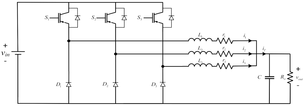
2. Circuit Topology and Analysis

Figure 1 shows the topology of a three-phase interleaved buck converter, which consists of three independent buck branches. Each branch is composed of an inductor L m ( m = 1 , 2 , 3 ) , a fully controlled switch S m , and a diode D m with r m , being the resistance of wire. C is the filter capacitor, R o is the load resistance, v i n and v o u t are the input voltage and output voltage, respectively. Each branch is driven by a switch signal with the same frequency, and the switching excitation signal of each branch has a phase difference of 1/3 of a cycle, i.e., a phase shift angle of 120 degrees.

2.1. Normal Operation

During the normal operation of the three-phase interleaved buck converter, according to Kirchhoff’s law of current, the output current can be given by the following formula
i T = i 1 + i 2 + i 3
where i 1 , i 2 , and i 3 are the inductance currents of each branch. i T is the total current of the inductor currents.
Generally, the design of each branch should satisfy the symmetry relation; therefore,
L 1 = L 2 = L 3 = L
d 1 = d 2 = d 3 = D
where d 1 , d 2 , and d 3 are the duty ratios of switch S 1 , S 2 , and S 3 , respectively.
According to the principle of the volt second balance of inductors, we can obtain
V o V i n = D
where V o and V i n are the average values of the output voltage and input voltage, respectively.

2.2. Analysis under Healthy Conditions

In this paper, we study a three-phase interleaved buck converter working in CCM. We assume that the circuit parameters of each branch are exactly the same and that the switch driving signal is only different in phase shift. Under the above conditions, only one branch of converter needs to be analyzed. Therefore, the analysis of a single-phase buck circuit is taken as an example, and then it is extended to the three-phase interleaved buck converter. Each branch has two modes: one is switch on, and the other is switch off. When S m is in the ON state, as an energy storage element, the current of the inductor increases. The expression of the differential equation is given as
L d i L d t = V i n V o
Similarly, the corresponding differential equation is written as follows when S m is turned off,
L d i L d t = V o
From (5) and (6), the inductance current waveform of each branch in two switching cycles is roughly shown in Figure 2, which is expressed as
i L ( t ) = I 2 I 1 D T c t + I 1 , t 0 , D T c I 1 I 2 ( 1 D ) T c ( t T c ) + I 1 , t D T c , T c
where T c is the switching cycle and t is the time.
From Fourier series theory, (7) can be rewritten as
i L ( t ) = A 0 + i = 1 a i cos 2 π i t T c + b i sin 2 π i t T c = A 0 + i = 1 A i sin 2 π i t T c + φ i
where A 0 is the DC component and A i and φ i represent the amplitude and the phase angle of ith (i > 0) harmonic, respectively.
From (5)–(7), a i and b i can be rewritten as follows
a i = 1 2 π 2 V i n T c L 1 i 2 cos 2 π i D 1
b i = 1 2 π 2 V i n T c L 1 i 2 sin 2 π i D
Based on the trigonometric function,
A i = a i 2 + b i 2
φ i = arctan a i b i
Substituting (9) and (10) into (11), A i is rewritten as
A i = V i n T c π 2 L 1 D 1 i 2 sin i π D
According to the formula (13), the amplitude of the ith harmonic component of the inductance current in each branch is affected by the input voltage V i n , duty cycle D, inductance value L, and switching frequency f c under healthy conditions. This denotes that there is no relationship between the ripple in the inductance current and the system load.

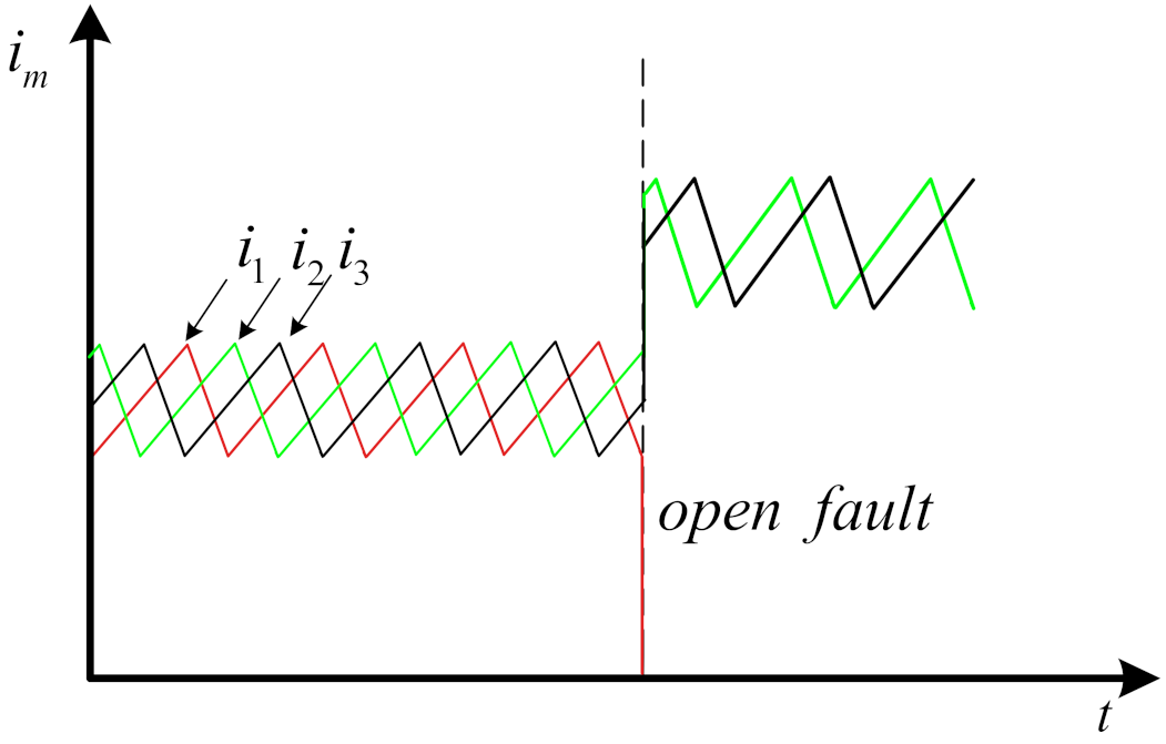
2.3. Analysis under OCF Conditions

In the case where an OCF occurs, the balance presented in the healthy and normal working state will be broken. Whenever an OCF occurs in any branch, it will affect the three-phase interleaved buck converter, such as the branch current, the ripple of the output voltage, and the output current.
Figure 3 shows the changing trend of the branch currents that result from branch 1 having an open circuit fault, where the current of each branch has a different changing trend after the fault occurs, and i 1 begins to drop immediately to zero. At the same time, i 2 and i 3 are affected by the fault, which makes their overall current begin to increase until they reach a value where the current waveform fluctuates up and down. If one branch current is missing, the fundamental frequency of the total output current ripple will change from 3 f c to f c , and three phase balancing will no longer be possible.
I 1 = 0 , I 2 = I 3
where I 1 , I 2 , and I 3 are the average inductance currents of branch 1, branch 2, and branch 3, respectively.
In order to show the influence of different OCFs on the harmonic components of the same branch without an OCF, four different simulations were conducted in Matlab/Simulink. For the same branch, the different orders of the current harmonic components are shown in Figure 4. Where, case-1, case-2, case-3, and case-4, respectively, indicate that there are still 1, 2, 3, and 4 branches working normally after the OCF in the interleaved buck converter.
As shown in Figure 4, once the circuit parameters and D are determined, the number of parallel branches does not affect the current fluctuation of normal branches despite the OCF. The fluctuation of current does not change with the change of branches, which is consistent with (13). In short, only the DC component of the inductor current will be affected, and the harmonic component will not be. We obtained that the fundamental frequency amplitude was dominant in the harmonic components.
In Figure 1, R o and C are connected in parallel to form a first-order inertial link, and therefore the output voltage v o u t only changes in amplitude and phase compared to the input current i T . The phase difference between the current harmonic components of each branch is still 120 degrees, and the amplitude is also equal after this link. The information between the currents at fault or non-fault can be presented by the voltage. The fault diagnosis method through extracting the characteristic values of the output voltage will be explained in the next section.

3. Proposed Fault Diagnosis Method and Reconfiguration

In this section, a fault diagnosis method based on output voltage applied in three-phase interleaved buck converter is proposed. The fault identification method is based on the harmonic amplitude ( A i ) and phase information ( φ ) of the output voltage at the switching frequency. With this method, only one voltage sensor is needed.

3.1. Fault Signals

When a break occurs in a branch, the three branches will no longer share the same current, and the three-phase balance at the output will be broken. From a phase perspective, this will change the harmonic phase at the switching frequency ( φ s w ) of the output voltage. The trends of φ s w of the output voltage under different OCFs are shown in Figure 5a.
As the fundamental frequency of v o u t is three times the switching frequency, the harmonic amplitude at the switching frequency ( A s w ) of v o u t is equal to zero when the system works in a healthy state. From (13), the harmonic component amplitude of one branch is not affected by the OCF. If an OCF occurs in one branch, the A s w of the output voltage will be greater than zero. The trends of A s w of the output voltage under different OCFs are shown in Figure 5b.
From Figure 5a, when an OCF occurs in branch 1, branch 2, and branch 3, the phase angle change values Δ φ s w of v o u t are different. If an OCF occurs in branch 1, Δ φ s w is approximately −120 degrees. If an OCF occurs in branch 2, Δ φ s w is approximately −240 degrees ( 120 ). If an OCF occurs in branch 3, Δ φ s w is approximately 0 degrees.
To improve the accuracy of the fault identification algorithm and preventing miscalculation or failure of the identification algorithm, the proposed diagnosis method integrates A s w and φ s w as fault characteristic information. From Figure 5b, A s w will change suddenly after the fault occurs. In order to prevent the influence caused by the accidental jump of A s w , it is necessary to set a threshold ( A r e f ) to determine whether the change of A s w is caused by an OCF.

3.2. Fault Diagnosis Algorithm

To represent the instantaneous state corresponding to each branch OCF, the variable F D is defined in the proposed fault diagnosis algorithm. A s w and φ s w are used as criteria for fault diagnosis. Figure 6 shows the flow steps of the proposed fault detection scheme.
In the proposed scheme, a voltage sensor is used to measure the voltage signal at the output of the three-phase interleaved buck converter. A s w and φ s w in one cycle are obtained by using the Fourier series theory. Once the desired A s w is obtained, it is compared with a pre-defined threshold value A r e f to determine whether the value is caused by an OCF. If the amplitude change is caused by a fault, the next step is to calculate Δ φ s w of the phase after an OCF has occurred, which is used to diagnose which branch has the fault. Here, Δ φ s w is expressed as
Δ φ s w = φ s w φ o
where φ o is the harmonic phase angle at the switching frequency before failure.
In the application of the diagnosis algorithm in this paper, the judgment intervals of Δ φ s w for the OCFs of branch 1, branch 2, and branch 3 are taken as ( 130 , 110 ), ( 110 , 130 ), and ( 10 , 10 ), respectively. If the fault occurs in branch 1, F D will be set to 1; for OCFs of branch 2, the F D value is 2; and for OCFs of branch 3, the F D value is 3.

3.3. Reconfiguration after an OCF

Whenever the three-phase interleaved buck converter has an OCF, the compensation measurement should be taken as soon as possible to reduce the impact of a high ripple voltage on the output load. After identifying in which branch the fault occurred, the phase shift angle of the switch excitation signal of the remaining healthy phase needs to be reconfigured, which can effectively reduce the voltage ripple. Table 1 lists the corresponding adjustment combinations of phase shift angles under different branch faults.
As shown in Table 1, in order to reduce the output ripple, the phase difference between the switch excitation signals is changed from the original healthy phase difference of 120 degrees to the remaining healthy phase difference of 180 degrees.

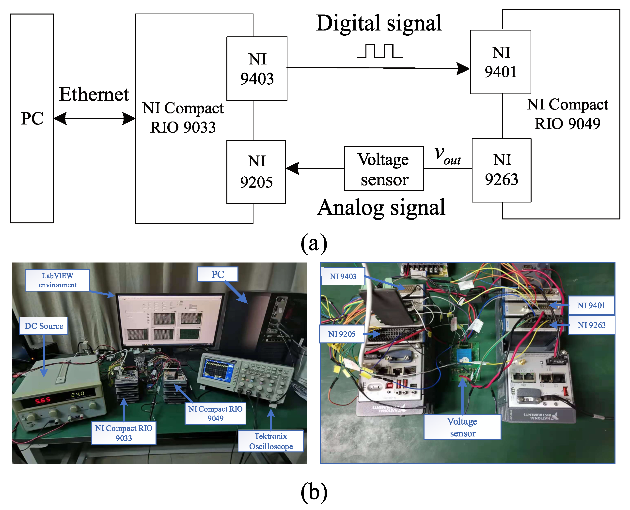
4. Experimental Evaluation

For validating the effectiveness of the proposed diagnosis method, an experimental test was performed on a hardware-in-the-loop (HIL) test platform [13]. Figure 7 shows the test platform, which was mainly composed of LabVIEW software and NI CompactRIO-9049. NI CompactRIO-9049 is a robust and high-performance embedded controller made up of an Intel Atom quad core processor, NI-DAQmx support, and SD card slot for data recording. It includes a LabVIEW FPGA module with support for the Kintex-7 325T FPGA. A HIL test platform for three-phase interleaved buck converter was built on NI CompactRIO-9049.
The signaling between the diagnostic algorithm and the circuit model was achieved through an analog output module NI-9263, an analog input module NI-9205, and digital input/output modules NI-9401/NI-9403 produced by NI. NI CompactRIO-9033 was selected as the controller of the test platform. For the subsequent processing and analysis of the experimental data, the data obtained from the test was saved in the host computer. The system and control parameters are given in Table 2.

4.1. Validity Verification

In this subsection, the effectiveness of the proposed method is verified. First, comparative experiments were performed with and without the proposed diagnosis method. The output voltage and branch currents are shown and analyzed in the following part. Secondly, experiments of OCFs in different branches were carried out. The output voltage ripple and the fault diagnosis response time were calculated and are marked in the following figures. Figure 8 shows the current waveforms of branch 1 and the output voltage when the open circuit fault happens in branch 1 without the proposed method. It is clear that i 1 began to drop immediately until it reached 0. The voltage ripple in the output voltage increased from 0.25 to 3.12 V. In addition, the dynamic transition process time Δ t was 0.00181 s—about two switching cycles.
For the proposed algorithm, the experiments of OCF and robustness verification are presented in Section 4.2. Figure 9 shows the waveforms of the current, output voltage, F D corresponding to the OCF, A s w of the output voltage and φ s w of the output voltage. It is clear that the output voltage ripple increased from 0.25 to 3.20 V after the fault. F D jumped quickly from 0 to 1, which denotes that an OCF was detected. As a result of the implementation of the proposed algorithm, the output voltage ripple was reduced to 0.42 V. The dynamic changes of A s w and φ s w can be clearly seen from Figure 9d,e.
Similarly, Figure 10 and Figure 11 show the waveforms of the current, output voltage, and F D after a fault in branch 2 and branch 3, respectively, with the proposed diagnosis method. It is clear that the faults were diagnosed accurately and quickly.

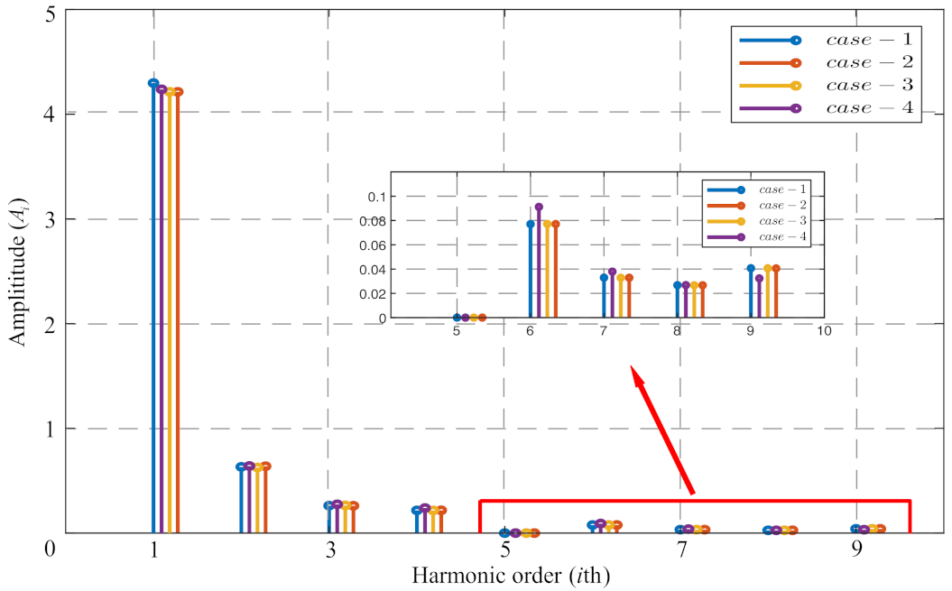
4.2. Robustness Verification

Load leap will cause changes in the branch current as well as instantaneous fluctuations in the output voltage. In order to test the robustness of the proposed diagnosis method, an experiment with sudden changes in the load resistance was performed [28]. Figure 12 shows the case of a sudden change in the load resistance R o , which jumped from 1 to 0.8 Ω at t = 0.36410 s. Despite the output voltage and branch currents fluctuating when the load resistance changed, F D remained at 0. The proposed diagnosis method demonstrated good robustness.

5. Conclusions

In this research, we proposed an OCF diagnosis and reconfiguration method for three-phase interleaved buck converters based on the output voltage. The proposed method enabled OCFs to be detected and located accurately. The reconfiguration minimized the ripple of the output voltage and improved the operating performance of the interleaved buck converter. Experimental verification of the proposed principle and method were conducted on a HIL test platform. The results indicate that OCFs were accurately diagnosed with the proposed method, which also demonstrated good robustness.
The proposed algorithm can be applied to multi-phase interleaved buck converters by adjusting the judgment index Δ φ s w according to the number of branches. Given the similarities between the multi-phase interleaved buck circuit and the multi-phase interleaved boost circuit, the method proposed in this paper can be extended to interleaved boost converters by using the total input current of the interleaved boost converter as the diagnostic index.
The proposed method is robust, simple, and fast and was shown to diagnose open-circuit faults effectively and accurately with a small amount of calculation.

Author Contributions

Conceptualization, P.L.; methodology, P.L.; software, X.L. and T.Z.; validation, X.L. and T.Z.; writing—original draft preparation, X.L. and P.L.; writing—review and editing, P.L.; funding acquisition, T.Z. All authors have read and agreed to the published version of the manuscript.

Funding

This research was funded by the Knowledge Innovation Program of Shenzhen City (Fundamental Research, Free Exploration) grant number JCYJ20170306141926192.

Conflicts of Interest

The authors declare no conflict of interest.

Abbreviations

The following abbreviations are used in this manuscript:
OCFopen circuit fault
IGBTInsulated Gate Bipolar Transistor
MOSFETMetal Oxide Semiconductor Field Effect Transistor
HILhardware-in-the-loop
DCdirect current
MMCmodular multilevel converter
CCMcontinuous conduction mode

References

  1. Ni, L.; Patterson, D.J.; Hudgins, J.L. Maximum power extraction from a small wind turbine using 4-phase interleaved boost converter. In Proceedings of the IEEE Power Electronics and Machines in Wind Applications, Lincoln, NE, USA, 24–26 June 2009; pp. 1–5. [Google Scholar]
  2. Ahn, Y.; Jeon, I.; Roh, J. A Multiphase Buck Converter With a Rotating Phase-Shedding Scheme For Efficient Light-Load Control. IEEE J. Solid State Circuits 2014, 49, 2673–2683. [Google Scholar] [CrossRef]
  3. Zhang, Z.; Zhou, H.; Deng, C.; Song, Q. Multiloop interleaved control for three-level buck converter in solar charging applications. IEICE Electron. Express 2018, 15, 20180369. [Google Scholar] [CrossRef] [Green Version]
  4. Antoszczuk, P.D.; Retegui, R.G.; Wassinger, N.; Maestri, S.; Funes, M.; Benedetti, M. Characterization of Steady-State Current Ripple in Interleaved Power Converters Under Inductance Mismatches. IEEE Trans. Power Electron. 2014, 29, 1840–1849. [Google Scholar] [CrossRef]
  5. Gu, Y.; Zhang, D. Interleaved Boost Converter with Ripple Cancellation Network. IEEE Trans. Power Electron. 2013, 28, 3860–3869. [Google Scholar] [CrossRef]
  6. Garcia, O.; Zumel, P.; de Castro, A.; Cobos, A. Automotive DC-DC bidirectional converter made with many interleaved buck stages. IEEE Trans. Power Electron. 2006, 21, 578–586. [Google Scholar] [CrossRef]
  7. Carbajal-Retana, M.; Hernandez-Gonzalez, L.; Ramirez-Hernandez, J.; Avalos-Ochoa, J.G.; Guevara-Lopez, P.; Loboda, I.; Sotres-Jara, L.A. Interleaved Buck Converter for Inductive Wireless Power Transfer in DC–DC Converters. Electronics 2020, 9, 949. [Google Scholar] [CrossRef]
  8. Bento, F.; Marques Cardoso, A.J. A comprehensive survey on fault diagnosis and fault tolerance of DC-DC converters. Chin. J. Electr. Eng. 2018, 4, 1–12. [Google Scholar] [CrossRef]
  9. Yang, S.; Bryant, A.; Mawby, P.; Xiang, D.; Ran, L.; Tavner, P. An Industry-Based Survey of Reliability in Power Electronic Converters. IEEE Trans. Ind. Appl. 2011, 47, 1441–1451. [Google Scholar] [CrossRef]
  10. Guilbert, D.; N’Diaye, A.; Gaillard, A.; Djerdir, A. Fuel cell systems reliability and availability enhancement by developing a fast and efficient power switch open-circuit fault detection algorithm in interleaved DC/DC boost converter topologies. Int. J. Hydrogen Energy 2016, 41, 15505–15517. [Google Scholar] [CrossRef]
  11. Shahbazi, M.; Zolghadri, M.R.; Ouni, S. Fast and simple open-circuit fault detection method for interleaved DC-DC converters. In Proceedings of the 7th Power Electronics and Drive Systems Technologies Conference (PEDSTC), Tehran, Iran, 16–18 February 2016; pp. 440–445. [Google Scholar]
  12. Shahbazi, M.; Jamshidpour, E.; Poure, P.; Saadate, S.; Zolghadri, M.R. Open- and Short-Circuit Switch Fault Diagnosis for Nonisolated DC–DC Converters Using Field Programmable Gate Array. IEEE Trans. Ind. Electron. 2013, 60, 4136–4146. [Google Scholar] [CrossRef] [Green Version]
  13. Jamshidpour, E.; Poure, P.; Saadate, S. Switch failure diagnosis based on inductor current observation for boost converters. Int. J. Electron. Theor. Exp. 2016, 103, 1498–1509. [Google Scholar] [CrossRef]
  14. Bento, F.; Marques Cardoso, A.J. Fault tolerant DC-DC converters in DC microgrids. Proceedings of IEEE Second International Conference on DC Microgrids (ICDCM), Nuremburg, Germany, 27–29 June 2017; pp. 484–490. [Google Scholar]
  15. Ahmad, M.W.; Gorla, N.B.Y.; Malik, H.; Panda, S.K. A Fault Diagnosis and Postfault Reconfiguration Scheme for Interleaved Boost Converter in PV-Based System. IEEE Trans. Power Electron. 2021, 36, 3769–3780. [Google Scholar] [CrossRef]
  16. Wei, H.; Zhang, Y.; Yu, L.; Zhang, M.; Teffah, K. A New Diagnostic Algorithm for Multiple IGBTs Open Circuit Faults by the Phase Currents for Power Inverter in Electric Vehicles. Energies 2018, 11, 1508. [Google Scholar] [CrossRef] [Green Version]
  17. Pei, X.; Nie, S.; Chen, Y.; Kang, Y. Open-Circuit Fault Diagnosis and Fault-Tolerant Strategies for Full-Bridge DC–DC Converters. IEEE Trans. Power Electron. 2012, 27, 2550–2565. [Google Scholar] [CrossRef]
  18. Givi, H.; Farjah, E.; Ghanbari, T. Switch and Diode Fault Diagnosis in Nonisolated DC–DC Converters Using Diode Voltage Signature. IEEE Trans. Ind. Electron. 2018, 65, 1606–1615. [Google Scholar] [CrossRef]
  19. Chen, Y.; Pei, X.; Nie, S.; Kang, Y. Monitoring and Diagnosis for the DC–DC Converter Using the Magnetic Near Field Waveform. IEEE Trans. Ind. Electron. 2011, 58, 1634–1647. [Google Scholar] [CrossRef]
  20. Pei, T.; Hao, X. A Fault Detection Method for Photovoltaic Systems Based on Voltage and Current Observation and Evaluation. Energies 2019, 12, 1712. [Google Scholar] [CrossRef] [Green Version]
  21. Zhuo, S.; Gaillard, A.; Xu, L.; Liu, C.; Paire, D.; Gao, F. Observer-Based Robust Switch Open-Circuit Fault Diagnosis of DC-DC Converter for Fuel Cell Application. In Proceedings of the IEEE Industry Applications Society Annual Meeting, Baltimore, MD, USA, 29 September–3 October 2019; pp. 1–6. [Google Scholar]
  22. Zhuo, S.; Xu, L.; Gaillard, A.; Huangfu, Y.; Gao, F. Robust Open-Circuit Fault Diagnosis of Multi-Phase Floating Interleaved DC–DC Boost Converter Based on Sliding Mode Observer. IEEE Trans. Transp. Electrif. 2019, 5, 638–649. [Google Scholar] [CrossRef]
  23. Wassinger, N.; Penovi, E.; Retegui, R.G.; Maestri, S. Open-Circuit Fault Identification Method for Interleaved Converters Based on Time-Domain Analysis of the State Observer Residual. IEEE Trans. Power Electron. 2019, 34, 3740–3749. [Google Scholar] [CrossRef]
  24. Zhuo, S.; Gaillard, A.; Xu, L.; Liu, C.; Gao, F. An Observer-Based Switch Open-Circuit Fault Diagnosis of DC–DC Converter for Fuel Cell Application. IEEE Trans. Ind. Electron. 2020, 56, 3159–3167. [Google Scholar] [CrossRef]
  25. Hui, L.; Ke, M.; Poh, L.; Frede, B. Online Fault Identification Based on an Adaptive Observer for Modular Multilevel Converters Applied to Wind Power Generation Systems. Energies 2015, 8, 7140–7160. [Google Scholar] [CrossRef] [Green Version]
  26. Cen, Z.; Stewart, P. Condition Parameter Estimation for Photovoltaic Buck Converters Based on Adaptive Model Observers. IEEE Trans. Reliab. 2017, 66, 148–160. [Google Scholar] [CrossRef]
  27. Du, B.; He, Y.; Zhang, Y. Open-Circuit Fault Diagnosis of Three-Phase PWM Rectifier Using Beetle Antennae Search Algorithm Optimized Deep Belief Network. Electronics 2020, 9, 1570. [Google Scholar] [CrossRef]
  28. Bento, F.; Marques Cardoso, A.J. Fault diagnosis in DC-DC converters using a time-domain analysis of the reference current error. In Proceedings of the IEEE Industrial Electronics Society, Beijing, China, 29 October–1 November 2017; pp. 5060–5065. [Google Scholar]
Figure 1. Three-phase interleaved buck converter topology.
Electronics 10 01451 g001
Figure 2. Inductor current waveform in a branch.
Electronics 10 01451 g002
Figure 3. An inductor current after an OCF.
Electronics 10 01451 g003
Figure 4. The harmonic components of the current.
Electronics 10 01451 g004
Figure 5. The trends of φ s w and A s w of the output voltage when different OCFs occur: (a) phase angle change, and (b) amplitude change.
Electronics 10 01451 g005
Figure 6. The flow steps of the proposed algorithm.
Electronics 10 01451 g006
Figure 7. The test platform. (a) Block diagram, and (b) experimental test bench.
Electronics 10 01451 g007
Figure 8. Waveforms after an OCF in branch 1 without the proposed method: (a) branch 1 current, and (b) the output voltage at load side.
Electronics 10 01451 g008
Figure 9. Waveforms after an OCF in branch 1 with the proposed method: (a) branch 1 current, (b) the output voltage at load side, (c) instantaneous state F D corresponding to OCF, (d) A s w of the output voltage, and (e) φ s w of the output voltage.
Electronics 10 01451 g009
Figure 10. Waveforms after an OCF in branch 2 with the proposed method: (a) branch 2 current, (b) the output voltage at load side, and (c) the instantaneous state F D corresponding to the OCF.
Electronics 10 01451 g010
Figure 11. Waveforms after an OCF in branch 3 with the proposed method: (a) branch 3 current, (b) the output voltage at load side, and (c) the instantaneous state F D corresponding to an OCF.
Electronics 10 01451 g011
Figure 12. Waveforms when the load resistance R o jumped from 1 to 0.8 Ω at t = 0.3641 s with the proposed method: (a) branch 1, branch 2, and branch 3 currents, (b) the output voltage at load side, and (c) the instantaneous state F D corresponding to an OCF.
Electronics 10 01451 g012
Table 1. Adjustment combinations of phase shift angles under different branch faults.
Faulty BranchPhase-1 ShiftPhase-2 ShiftPhase-3 Shift
Branch 1- 0 180
Branch 2 0 - 180
Branch 3 0 180 -
Table 2. The system and control parameters.
ParameterSymbolValue
Input voltage v i n 60 V
Inductance L m 1.35 mH
Branch resistance r m 0.01 Ω
CapacitanceC470 μ F
Load resistance R o 1 Ω
Duty cycleD0.4
Switching frequency f c 1 kHz
Sampling frequency f s 40 kHz
Publisher’s Note: MDPI stays neutral with regard to jurisdictional claims in published maps and institutional affiliations.

