1. Introduction
The electricity production from renewable-based Distributed Generation (DG) technologies has rapidly increased due to the growth of electrical energy consumption and environmental concerns [
1,
2]. The integration of microgrids is a pathway to facilitating a flexible integration of DG, loads and energy storage systems [
3,
4]. In the microgrid, the loads and renewable-based energy resources have random and unpredictable behavior. Therefore, using energy storage systems and programmable generators is necessary to control the voltage, frequency and power exchanged with the upstream network [
5,
6]. The energy capacity constraint is the most significant limitation in common energy storage systems, such as batteries, leading to the development of new electrical energy storage solutions [
7,
8].
The production of CH
4 from CO
2 using renewable energy surplus, known as Power to Gas (P2G), represents a potential high-capacity energy storage technology [
9,
10,
11,
12]. The P2G process links the power grid with the natural gas grid by converting CO
2 and electrical energy into a grid-compatible, synthetic natural gas (mostly CH
4), increasing the overall resilience of the energy system and decreasing its price. The position and perspectives of P2G plants for managing high contributions of renewable energies has been discussed previously [
13].
H
2 production through water electrolysis represents the state-of-the-art for P2G technology; however, the gas distribution grid is not prepared for H
2, contrary to methane, which limits the energy storage capacity. Alternatively, the chemical and biological production of methane is implemented in several pilot plants, spread around Europe [
14,
15]. However, both methanation options present drawbacks, e.g., requirement of an expensive catalyst, high operating temperature and pressure and limited efficiency [
14].
Bioelectrochemical systems performing electromethanogenesis (EMG-BES) were first proposed in 2009 as an alternative way to drive the reduction of CO
2 (dissolved into an aqueous medium) into CH
4 [
16]. This represented a milestone for the development of likely processes, producing different added-value chemicals and fuels from CO
2 and renewable energy surplus [
17]. The process is performed under mild operational conditions (20–35 °C and atmospheric pressure) and is driven by electroactive microorganisms, without the need of an expensive catalyst, meaning higher energy efficiency and potentially lower construction and operational costs compared to chemical methanation [
18]. Thus, P2G based on EMG-BES represents an innovative and flexible energy storage technology for renewable energy surplus (RES) management. It offers a suitable solution for seasonal energy storage of RES, and it enables the convergence of an electrical grid with an existing natural gas grid into one hybrid energy system [
19]. Besides, this technology can also help to reduce CO
2 emissions from industries, decarbonizing the electricity sector [
20].
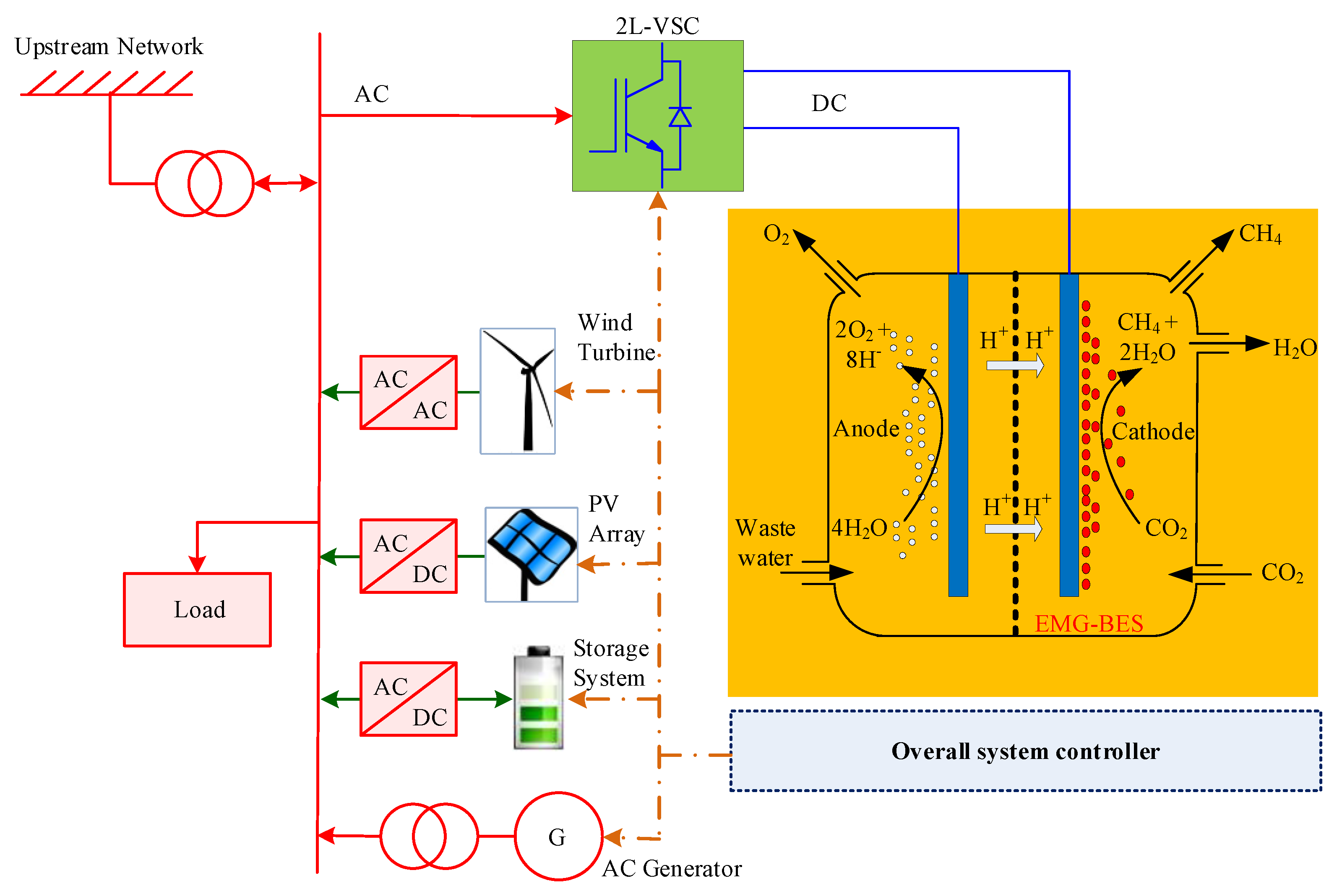
In this paper, bioelectrochemical power to gas stations based on an EMG-BES stack is discussed, based on preliminary data collected from a laboratory prototype [
21]. The technology has the ability to receive active power and exchange reactive power with the grid (
Figure 1). For achieving this goal, the proposed topology for the power converter, located upstream of the bioelectrochemical plant, is a two-level voltage source converter (2L-VSC) because: (1) the EMG-BES stack has to be fed by regulated DC voltage and (2) 2L-VSC can draw the sinusoidal current from the grid. Using 2L-VSC provides high power quality performance and grid support capability in contrast to other solutions such as diode rectifier and DC/DC converter in [
22]. The conventional control schemes of grid-connected 2L-VSCs cannot be used directly for this system because they are only designed to control variables such as
PQ (active/reactive powers),
PV (active power/AC terminal voltage),
VdcQ (DC link voltage/reactive power) and
VdcV (DC link voltage/AC terminal voltage) [
3]. However,
Vdc,
P and
Q need to be controlled at the same time for this application. Recently, Reference [
23] suggested a two-loop control scheme for BES applications that included an outer power loop and an inner current loop; however, this approach is not applicable because the DC link voltage must be controlled with 2L-VSC. Therefore, this paper proposes a control scheme that consists of three loops: an outer power loop, a middle DC link voltage loop and finally an inner current loop, which are implemented in the stationary reference frame. The contribution of the control scheme consists of three parts: (1) BES works a controlled PQ load with this method, (2) a new Proportional-Resonant (P + R) controller with harmonic compensation capability and anti-windup capability is to be used as the current controller and (3) a new DC-link voltage reference modifier, which defines the appropriate reference to keep the system stable. It is worth mentioning that the basic idea of this paper was already published by authors as a conference paper in [
24].
This paper is organized as follows. In
Section 2, the EMG-BES based energy storage system is briefly introduced, and a medium-scale laboratory prototype is presented. In
Section 3, the description of the proposed topology scheme for the electrical converter and its control system are presented. In
Section 4, the simulation results that allowed us to analyze the performance of the proposed controller are presented. Finally, the conclusions arising from this work are presented in
Section 5.
2. EMG-BES Stack
The standard BES reactor comprises an anode and a cathode, sometimes separated by an ionic exchange membrane [
25]. In the case of the developed EMG-BES technology, the reactor is membrane-less, and an electrical input drives the set of anode and cathode reactions, which would be otherwise thermodynamically unfavorable. At the cathode, electro-autotrophic microorganisms utilize CO
2 as a carbon source and electricity as the source of reduction equivalents to produce CH
4 [
26]. On the other hand, at the anode the organic matter contained in wastewater is oxidized by electroactive bacteria (EAB), transferring the required electrons to the cathode.
In [
9], a medium-scale EMG-BES prototype was built by connecting 45 cells (i.e., each pair of electrodes) in parallel, grouped by 3 into 15 single-chamber, membrane-less reactor modules. The voltage stack was increased from 0.7 to 18 V to guarantee a voltage drop near 1–1.2 V for each series-connected module. The voltage drop of each EMG-BES cell needed to be balanced to allow the proper operation of the anode and cathode and to convert the electrical current into methane. A passive voltage balancing system was adopted [
18].
The electrical stabilization time of the EMG-BES prototype, due to voltage variation from the open-circuit voltage (OCV) to operational voltage, was in the minute scale time. The peak of current observed when the voltage was applied was due to the self-capacitance of the bioelectrodes [
27]. This capacitance was produced by the electrons accumulated at the anode due to the spontaneous oxidation of organic matter by EABs and the high surface area of carbon material used as the electrode.
In terms of electrical current conversion to methane, this was slower than the shown electrical dynamics, resulting in difficult-to-quantify electrical-driven CH
4 production [
23]. This behavior (among other factors) caused the EMG-BES reactor to continue producing methane also when no energy input was applied.
Figure 2 shows experimental results of current vs. voltage for 15 parallel EMG-BES modules, wherein: (1) the level of current can be controlled by the input voltage; (2) the input voltage must be higher than 0.45 V and less than 1 V for linear operation of EMG-BES; moreover, a reverse current will flow into the DC source at low input voltages, and the EMG-BES saturates at voltages higher than 1 V, where the current remains constant and (3) all parallel modules behave similarly and tend to follow the same pattern. Therefore, the electrical characteristic of an EMG-BES pack, with several modules in series and parallel, can be interpreted from a module behavior since they operate together. In this paper, several modules are considered in parallel and series to make a 10 kW EMG-BES stack.
The considered model for the EMG-BES cell is shown in
Figure 3 [
10,
28]. The model parameters in
Table 1 are chosen based on the method mentioned by [
10] and data of experimental tests in the nominal state. In a stack with
ns series cell in each branch and
np parallel branches, the following parameters can be used in the model:
3. Proposed Topology and Associated Control Scheme
According to
Section 2, the EMG-BES stack must be fed by variable and regulated DC voltage to control the EMG-BES current. The applied voltage must be higher than the specific value (0.45 V for a cell with 0.7 V nominal voltage). Therefore, an AC/DC converter is required as an interface to connect the EMG-BES to the electrical grid. This paper proposes a 2L-VSC with an LCL filter for this purpose (
Figure 4). The hardware design of 2L-VSC is explained in [
29,
30] and is out of the scope of this paper. This paper aims to develop a control scheme for this system to feed an EMG-BES with a regulated voltage. With this control method, the EMG-BES works as an active load that can absorb a controlled active power from the grid and is able to exchange reactive power with the grid. The converted energy inside the EMG-BES adds a new degree of freedom which can be exploited to provide ancillary services such as energy management, flexibility, frequency regulation, voltage profile improvement and power oscillation damping.
In this study, the overall system controller is supposed to send the power reference (
P* and
Q* in
Figure 4) to the EMG-BES power plant. This power reference can be determined by distribution system operators (DSOs) to manage the grid by ancillary services. The latter, counting on a 2L-VSC converter as an interface with the grid, converts the power reference to a DC link voltage reference, then it is tracked by the voltage and current controller.
For the linear operation of 2L-VSC, the relationship between the DC side and AC side voltage can be expressed as in Equation (2) (see also
Figure 5):
where
Vi,
Vdc and
m are the maximum phase voltages of the 2L-VSC, DC bus voltage and 2L-VSC modulation index, respectively. The maximum value of
m for linear operation of the 2L-VSC depends on the switching method and can be a value between 1 and 1.154 [
31]. In terms of controllability, 2L-VSC becomes uncontrollable for
m higher than 1.1547; therefore, the DC bus voltage cannot reduce less than a specific value. This limitation must be considered in a loop scheme design.
The proposed control scheme consists of three main parts: (1) The outer power loop for DC link voltage reference generation, (2) the middle DC link voltage loop and (3) the inner current loop with a new PR controller with harmonic compensation and anti-windup capabilities.
In the outer loop, according to
Figure 6, the active power reference (
P*) is compared with the active output power of the 2L-VSC (
P), generating an error value. Then, this error is the input of a PI controller, which determines at the output the initial DC link voltage reference
Vdc ref. In the present application, the grid voltage is fixed, hence the 2L-VSC works in the linear region, the DC link voltage should be higher than the specific value (
Vdcmin). The DC link voltage reference modifier is proposed to keep the 2L-VSC converter under control and also to avoid instabilities in the system. The output of the DC link voltage reference modifier (
) is used as a reference value for the middle DC link voltage loop. The reference of current in the stationary reference frame can be found based on the output of the DC link voltage controller, reactive power reference and the positive sequence of PCC voltage. The current reference is tracked by the proposed proportional resonant controller with anti-windup and harmonic compensation capabilities.
3.1. DC Bus Voltage Reference Modifier
This part proposes a new DC bus voltage reference modifier to prevent converter instabilities. This method does not require the values of the grid voltage (
Vg) or the equivalent grid impedance (
Zg), and certificates the converter to stay stable for any active and power references. Considering the equivalent circuit diagram of the system in
Figure 7, the active and reactive powers (
P and
Q) absorbed by the 2L-VSC from the point of common coupling (PCC) can be written as follows:
where
V,
Vi and
δ are PCC voltage, 2L-VSC voltage and angle, respectively.
Xf is equal to 2 × π ×
fo wherein
fo is the grid frequency in Hz, and
S is apparent power. By squaring the relationships of
P and
Q in Equations (3) and (4) and arranging terms, the following expression can be obtained:
Therefore, the converter must produce the following voltage to exchange power with the grid:
Therefore, the minimum DC bus voltage (
Vdcmin) can be found as:
Figure 8 shows the minimum DC link voltage (
Vdcmin) based on active and reactive powers. It can be concluded that
Vdcmin is directly related to the reactive power and is almost independent of the active power.
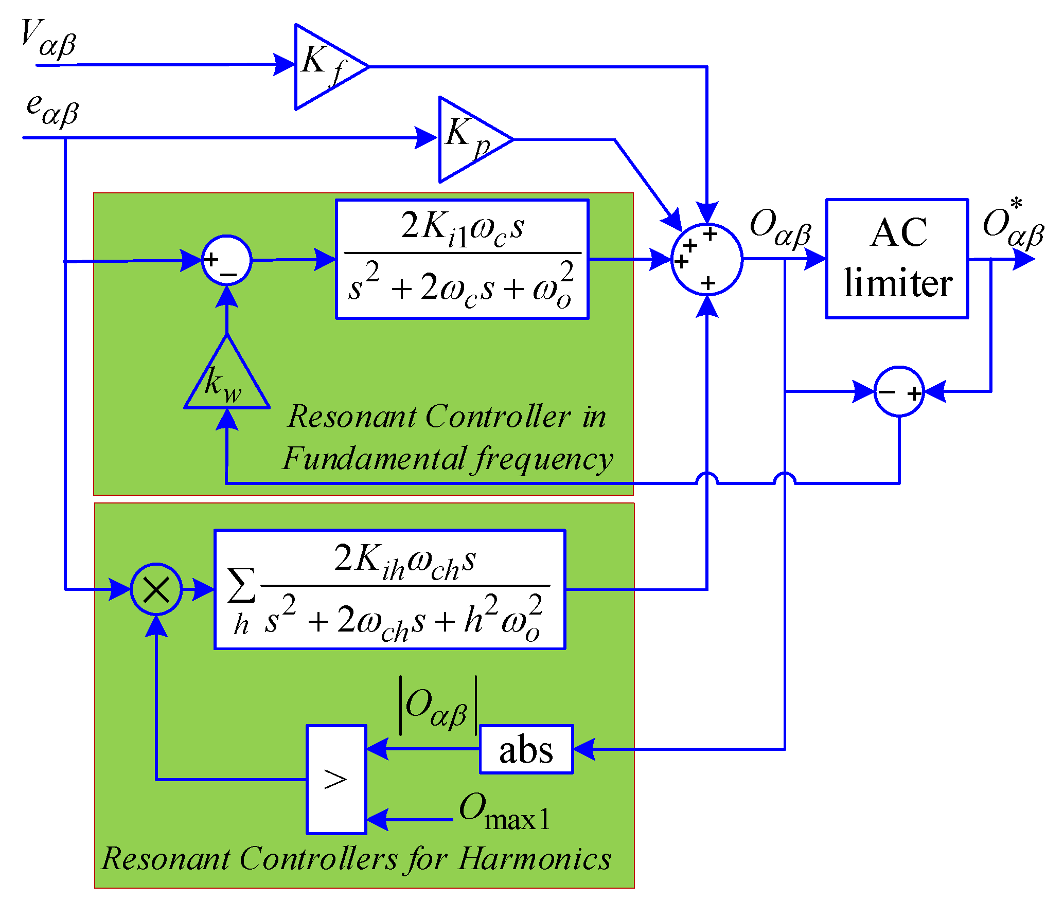
3.2. Proposed PR Controller
The anti-windup of the PR controller and the DC voltage reference modifier must work complementary to each other. In the transient case, the anti-windup part of the PR controller limits the input of the switching modulator (SM) and avoids the saturation of the integral terms of the PR controller. In steady-state, the DC voltage reference modifier does not allow the reduction of the DC-link voltage lower than a specific value, avoiding the saturation of the controller. For drawing a sinusoidal current from the grid, a PR controller with harmonic compensation capabilities should be used. Typical ones can be expressed by Equation (8):
where
h,
Kp,
Kih,
ωo and
ωch are the harmonic order, the proportional coefficient, the resonant coefficients, the resonant frequency and the resonant bandwidths, respectively. The output of the PR controller (input of switching modulator) has to be smaller than the specific value
Omax; otherwise, there will be over modulation. In over modulation, the switching frequency is reduced, and the waveforms at the converter’s output are distorted.
The suggested anti-windup scheme for the PR controller consists of three main parts (see
Figure 9): AC limiter, anti-windup for the resonant controller in fundamental frequency, and anti-windup for resonant controllers in the other frequencies. The AC limiter (ACL) to limit the input of SM can be considered as [
32]:
With this limiter, the SM input is not clipped and is always sinusoidal. The value of Omax is chosen based on the switching method.
The integrators within the controller may experience wind-up while a limiter hinders the output of a controller. In the proposed controller, the ACL is used inside of the anti-wind-up as the core block. If the absolute value of the output of the controller |Oαβ| is more than the threshold Omax1, the harmonics compensation is cancelled, so that the controller still can track the current reference at the fundamental frequency. In addition, the difference between the AC limiter (ACL) and the controller’s output lays mainly on the feedback signal to compensate the inputs of the integrators of the resonant controller in the fundamental frequency, so if the |Oαβ| is going higher than threshold Omax, the output of the PR controller is clamped by the AC limiter and the input of the resonant controller in the fundamental frequency is modified by the anti-windup scheme.
The main essential variables in the anti-windup scheme are the maximum available outputs of the PR controller (
Omax and
Omax1), which should be chosen based on
Vdc. The proposed values for thresholds are given as:
where
tdead and
Ts are the switching dead time and the switching period, respectively. The switching dead time reduces the maximum available output of the PR controller and also degrades the quality of the output current. However, these drawbacks can be easily overcome by using dead time compensation methods [
33].
4. Processor-in-the-Loop Results
The Processor-in-the-Loop (PiL) studies were carried out by OPAL-RT OP4510 to verify the effectiveness of the proposed control system for a BES-P2G station.
Figure 10 shows the schematic and setup of the implementation of the proposed system in OPAL-RT. The hardware part includes the EMG-BES model, switches, diodes, electrical components and voltage/current sensors as implemented in FPGA of OPAL-RT. The hardware part runs fast with a sample time of 875 ns. The control system is implemented in the CPU of OPAL-RT and runs slowly with a sample time of 10 µs. Due to the increase in the switching frequency, the time step of the real-time model should be much lower than the converter’s switching time step. Typical CPU-based real-time simulation can only realize a minimum time step of Ts ≥ 10 μs, which is affected by the large bus latencies in a CPU. Also, the OP4510 connects to an oscilloscope to monitor voltage, current and electrical power in real-time. The values of currents and voltages are routed from the FPGA based model to the DAC channels.
The parameters of 2L-VSC in the proposed BES-P2G are listed in
Table 2. A 10 kW EMG-BES module is modelled based on [
10], where it is supposed that 10 stacks with 70 V and 14.25 A rating are installed in series. Two simulations have been done to verify the performance of the proposed control system.
In the first test, the active power reference stepped up from zero to its nominal value (10 kW) and the reactive power reference was set to 0 Var. The obtained results are illustrated in
Figure 11 and
Figure 12. It can be seen in
Figure 11 that, although the reference power is zero, the DC bus voltage is limited to 543 V to prevent system instability, and consequently, the active power absorbed by the 2L-VSC converter was non-zero. Once the reference of active power was changed from zero to 10 kW, the DC bus voltage increased, and the reference and instantaneous value of active power were precisely the same. As shown in
Figure 11, the voltages of the LC filter’s capacitors were constant, and the grid current increased with a convenient and fast transient response. According to
Figure 12, the current reference in the stationary reference frame was correctly followed by the current controller, and before increasing the power reference, the peak of the switching duty cycle was close to its maximum value, and the system was controlled at the boundary of stability and instability. By increasing the power reference and the DC bus voltage, the value of the switching duty cycle was reduced, and the converter worked in the linear region. This fact can be seen in
Figure 12, where the peak of the switching duty cycle reduces from 1 to 0.85 after increasing the active power reference. The dynamics of the DC voltage variations are also shown in
Figure 12, which had the same behavior as a first-order system with a rise time of 60 ms and there was no overshoot in DC voltage.
The results for reducing active power reference from 10 kW to zero are shown in
Figure 13 and
Figure 14. The most important event happens at the moment that the active power reference changes: the DC voltage reference modifier and anti-windup of the P + R controllers prevent the switching duty cycle and system instability from increasing. The DC bus voltage decreases gradually in 40 ms, thus it is possible to continue connecting the proposed system to the grid.
The presented results show that BES-P2G with the proposed control can exchange power with the grid with a good transient response and zero steady-state error.


 ,
, 


