1. Introduction
Smart industries and sustainability are key features in the contemporary world [
1,
2,
3,
4]. The introduction of new materials, together with the integration of electronic systems in different objects, are leading the market towards new opportunities, services, and improved efficiency. Directly related to the industrial sector, according to the “Roadmap for research and innovation”, produced by the “Intelligent Factory Cluster Association” [
5], there are numerous research and innovation challenges that Italian manufacturing will have to address in the coming years. Among the intervention lines, two areas arouse particular interest: systems for the worker’s enhancement in factories and strategies, and methods and tools for industrial sustainability. Within them, this research article intends to contribute to the “New materials and new technologies for safety in the work-place” and the “Technologies and processes for reuse, remanufacturing and recycling of products, components and materials” Key Enabling Technologies. Specifically, this article will illustrate an original product innovation, born from the union of two areas of relevant interest, including that of Industry 4.0 and of the circular economy. MULTIFId is a multifunctional, intelligent, and economical panel that does not need an electric power supply, and is able to communicate with low emissions. It is produced from waste resulting from the industrial processing of paper and cardboard, and its main functions are the control of safety in factories, conducting panel monitoring, and the energy improvement of the building envelope. Although designed for factories, the innovative system can be used in other production sites and work places, as well [
6].
The smart functions are provided by means of suitable electronics that have been integrated inside the panel. The sensors system is composed of temperature and moisture sensors that allow for control of the hygroscopic conditions [
7,
8] and the energy efficiency of the panel. In addition, a passive RFID tag has been integrated for panel identification and localization [
9]. All sensors are battery-free and communicate through wireless protocol, thereby realizing an extremely low power and wires-free system that enhances the installation capability and portability of the panels. The required DC power supply is provided by an external reader as irradiated power. A reader is required in each room where panels are installed, also considering the maximum interrogation distance of the adopted device. These choices allow for the valid upgrade to traditional monitoring systems [
10,
11,
12,
13,
14], with improved features and minimum power consumption, and with respect to still valid alternatives proposed in the last years for industrial applications [
15,
16,
17,
18,
19,
20].
It is worth noting that when providing a passive tag to operators, for instance, as a wearable device, the reader can be used also for monitoring the relative position of the operator, with respect to the working space, thereby preventing dangerous operations or positions notifying the danger. This is achieved through the combined use of the multifunctional panels, wherein the volume can be divided into a 3D grid of location cells and the embedded tags may act as anchor points for the reader.
The multifunctional panels have been already realized and preliminary tests have been conducted in the laboratory, verifying both the sensing system and detection capability.
2. Panels and Sensors’ Integration
2.1. Panel Definition
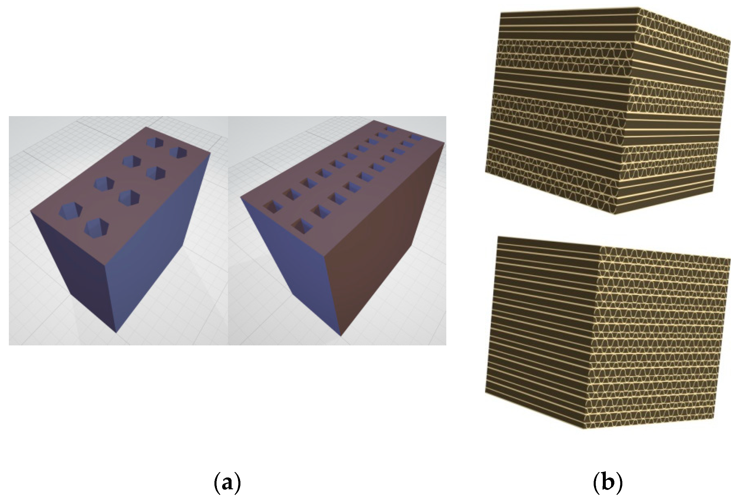
MULTIFId is a no-load-bearing and no-structural panel produced with paper and cardboard industrial waste. It mainly has two functions: to thermally insulate the envelope, in order to reduce the energy consumption of the building, and to act as a low-cost “support” and “container” for the sensory system. The project involved the development of two types of panels. Panel type (a) uses the processed cellulose/paper pulp in order to become compatible with 3D printing. Solutions based on two types of pulp have been developed and tested; one refined and one less pure, with the addition of water and different types of adhesives, natural and otherwise. Panel type (b) uses single layers of corrugated cardboard arranged in several layers.
The construction of the panel was preceded by an important industrial research phase, both to verify that there was not a similar panel capable of performing the functions of MULTIFId and to understand the characteristics to be achieved. Particular attention was paid to the optimization of the shape and the vacuum percentage of the section, in order to achieve resistance and thermal conductivity parameters similar to those of commercial products. For the panel type (a), square, rectangular, and hexagonal mesh sections have been designed. For panel type (b), sections were created with parallel layers, orthogonal by 1 × 1 and 2 × 2 (
Figure 1).
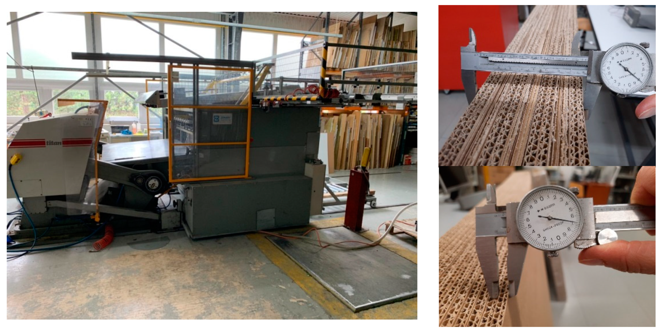
Once the prototypes were created (
Figure 2), it was possible to start the test phase in order to define the main elements of interest. For the thermal characterization, the theoretical calculation was combined with the experimental tests.
The theoretical calculation was performed in accordance with UNI EN ISO 6946 [
21]. For the conductivity values of cardboard and paper, we employed UNI 10351: 2015 [
22,
23]. The experimental tests were conducted both using the Guarded Hot Boxes created ad hoc for this project, employing the thermoflowmetric (HFM) approach.
Another point of interest is the task of connecting the integration between the panel, or sensory system support, and the sensory system itself. A slot has been designed according to three main elements: the geometry of the sensors, the slot positioning in the thickness of the panel, and the integration and connection between the sensor and the panel.
Finally, the panel will be treated with a specific cardboard fireproof paint, already widely available on the market for other cardboard panels [
24,
25].
2.2. Sensors Definition
The multifunctional panel described in the previous paragraph has been enhanced with electronic systems for smart functionalities. In particular, communication capability is provided by means of NFC and passive RFID tags, while humidity and temperature sensors are used for monitoring the health and moisture conditions of the panel. Sensing parameters have been chosen considering the nature and consistency of the panel itself and may be affected by degradation due to external agents during its lifetime.
Taking into account the nature and typical usage of the panel, beyond the ease of use of these structures during installation, a conventional electronic system with wired connections was not adequate, constituting a serious limitation for the integrability and installation of panels. In addition, battery-based devices may condition the installation of panels, signifying a main drawback and causing electronic systems to become vulnerable to battery replacement. An alternative solution could be to rely on the use of energy harvesting solutions [
26,
27], but they are difficult to realize in indoor environments on room walls. Thus, in order to maximize the cases of use and ease of installation, great effort has been made regarding the integration of wireless and battery-free sensors. The solution that has been adopted and validated for this study is based on the use of Farsens’ sensors [
28]; the company, Farsens, proposes a wide range of wireless sensor solutions and proprietary RFID integrated circuits that are able to supply and communicate with an external component (
Figure 3). Battery-free RFID sensors have been chosen, which represents the best solution for integration and does not demonstrate particular limitations for performance. In particular, the selected sensors are the EVAL01-Fenix-RM and the EVAL01-Hydro-H402 models. The first is a UHF RFID battery-free temperature sensor tag with transparent polycarbonate casing. The device features a TMP112 temperature sensor from Texas Instruments, with a temperature range from −40 °C to +85 °C. The sensor tag provides an accuracy of ±0.5 °C in temperature and a unique identification number, as well as the data from the digital temperature sensor. With a 2W ERP setup, the battery-less sensor can communicate to over 5 m. The second, the EVAL01-Hydro-H402 model, is a UHF RFID battery-free soil moisture sensor tag. The device features a resistive soil moisture sensor board with resistance values ranging between few hundreds of Ohms to tens of MOhm, depending on the moisture level; it has an operation range of 5 m when used in full passive with 2W ERP. Both sensors have dipole wideband antennas in PCB format that operate in the 860–960 MHz frequency band.
The sensors have been inserted in the above defined multifunctional panel, as shown in
Figure 4a, where dedicated slots have been created in each panel for sensors’ installation in the middle section of the structure. A further thin layer can be also applied in the final panel to hide the electronic systems without compromising performance (
Figure 4b), due to the used materials and low thickness.
Initially, several tests have been performed with independent sensors and devices, as shown in
Figure 5, with the aim to verify the reliability of measurements performed with Farsens devices. Connectivity was monitored with wireless devices and NFC protocol. The results are satisfactory, having demonstrated a good agreement between different measurement systems and so exhibiting no end towards the use of integrated and battery-free solutions.
Some further considerations relative to noise-related issues are specified. Temperature sensors embedded in the panel are digital devices; the decision to use digital sensors was adopted to ensure very low power consumption on one side, and robust communications on the other. In addition, the use of a significant number of bits in the measurement codification ensures that it possible to read accurate data; for instance, the resolution of the temperature sensor is 0.0625 °C. Moisture sensors are resistive, but they have a low-pass filter, with a very low cut-off frequency for noise filtering. Moreover, it is worth noting that in the considered application, an extremely high resolution is not necessary; thus, possible small variations or inaccuracies of the measurement data do not affect the system performance. As a consequence, the sensing system is intrinsically robust against noise issues.
3. Sensor Network Design
The sensor network has been designed with the aim of obtaining a safe working environment shared between workers, equipment, and robots. As a result, sensors’ position, choice, and network management have been optimized for this purpose. A smart network with very low power consumption has been defined and tested.
3.1. Sensor Network Definition
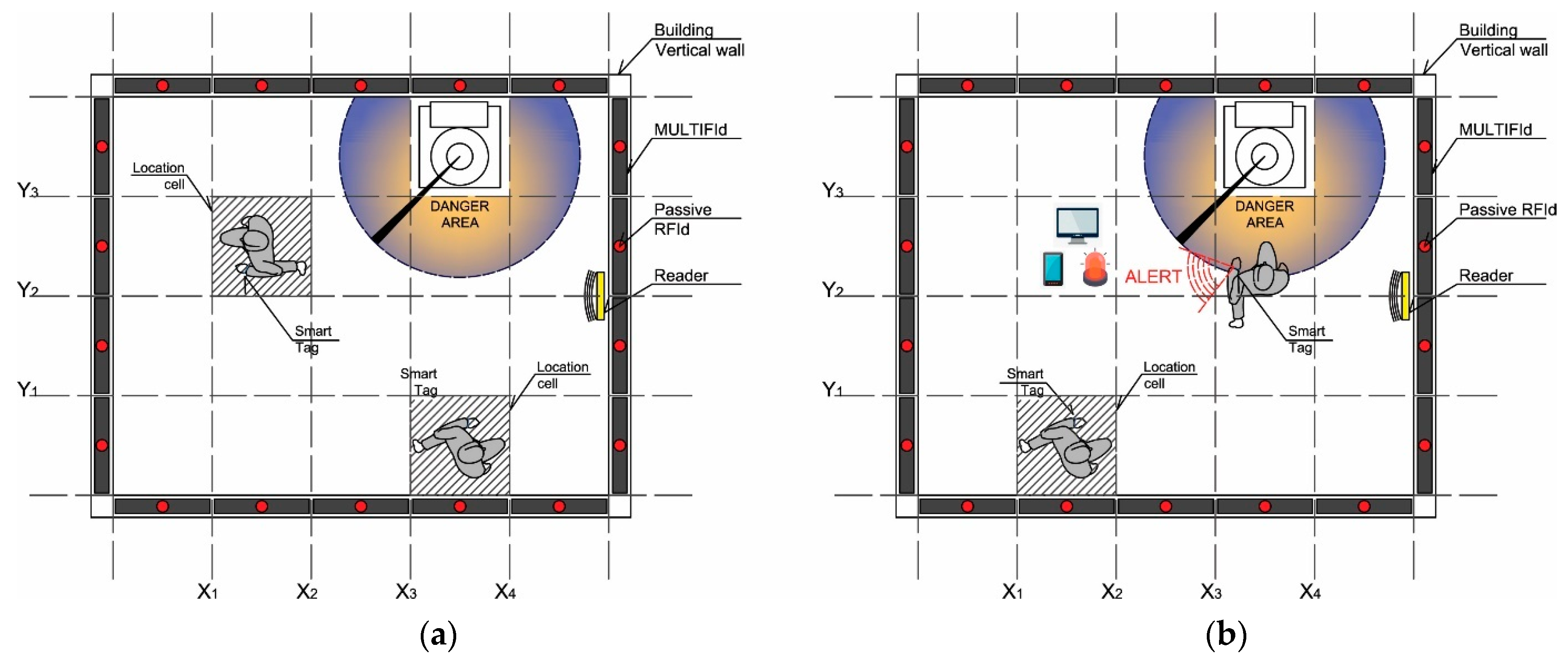
The idea is to use the above defined multifunctional panel on all walls of a facility, together with passive RFID tags suitably positioned on the walls, and a tag reader in each room. Thereby, a smart cell grid is created, as shown in
Figure 6a,b, in the context of a typical room. The multifunctional panels, with embedded sensors, are represented by dark grey rectangles; the passive RFIDs are localized through the small red dots in the middle of each panel. A cartesian grid (
x,
y and
z axes) is defined and localization of dangers or objects becomes possible, as each tag becomes an anchor point for the localization systems, driven by an active reader. The environmental conditions are monitored through the Farsens sensors, as well as through the positions of critical elements and operators. In fact, if operators are equipped with passive tags, their position and relative distance from critical objects can be easily identified. In
Figure 7, an example scenario is provided; if an operator, provided by a passive tag (for instance, a wearable or an armlet device), moves close to an unsafe area, it is localized by the reader close to a danger tool, and some alerts could be automatically activated to discourage further action or to warn those in charge of surveillance.
Localization is not carried out by means of real time monitor techniques, as they have some drawbacks, in particular, for what concerns the stress of the electronic system, with continuous interrogation of tags and needs of triangulation. These characteristics, still allowing for a more accurate localization, appear to be not adequate for a very low power system with passive tags. The better solution that has been identified and adopted is based on the discretization of the volume in location cells. As a result, the electronics are less stressed and power consumption is lower, without significantly affecting the positioning of each element. The division of each volume in location cells still allows for the constant monitoring of each element, but with a reasonable inaccuracy; while it does not affect the analysis of hygroscopic characteristics of structural elements. Additionally, quality readers are available in the market with an interrogation distance of up to 15 m, thus, there are many devices suitable for the detection and monitoring of closed spaces.
It is worth noting that a 15 m range is currently a technological limitation. In practical applications, if production halls are wider and organized as open spaces, the proposed solution should be coupled with semi-passive RFID tags that would allow for a wider interrogation range. A further solution should be consistent with the realization of small columns or totems in the open space, as for instance, close to dangerous equipment, in order to install tags or readers at those specified locations and prevent dangerous outcomes. In general, when close to equipment, no stopping points should be near to the installation of active tags, as a power supply is available and their power consumption is negligible.
3.2. Software and Algorithm Definition
After defining the hardware requirements and characteristics, great effort had been devoted to defining a suitable RFID Middleware that would be able to process different functions, including data storage and management, data monitoring, management and application–level service interface, and device drivers’ interface. In addition, it functions also to service-oriented interfaces based on Java, J2EE, .NET, and web service. The solution that has been adopted in this work is the Application Level Events (ALE) di EPCglobal. The ALE interface provides useful functionalities for the reception, filtering, and grouping of events originating from RFID readers.
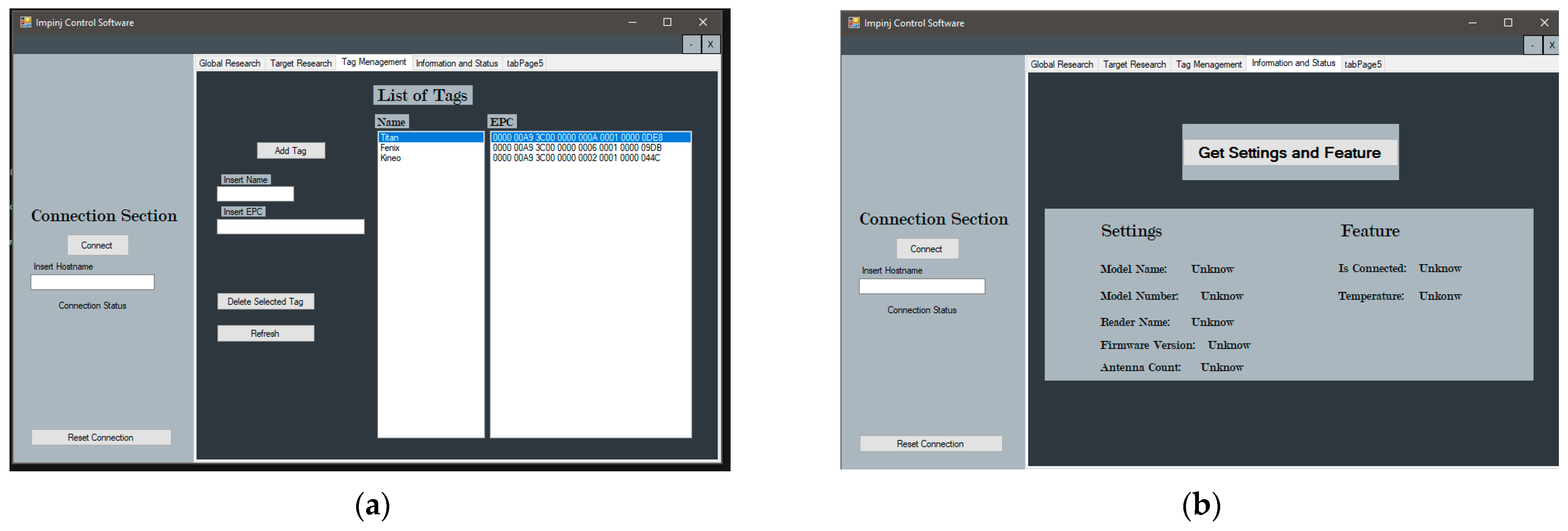
Software has been developed in Visual Studio as an .NET desktop application. Octane SDK libraries have been used for the management of the reader and the communication settings. Great effort has also been devoted to the localization of tags, as different algorithms have been tested and evaluated. As discussed in the previous section, the solution to split the volume in location cells has been adopted, defining a set of anchor points on the multifunctional panels. A simple user interface has been realized for testing the system, as shown in
Figure 8. In
Figure 8a, the database access and management shell are reported, while in
Figure 8b, the reader status can be monitored.
Following the operation steps, first, a connection is established with the reader, which is then configured with the setup that has been chosen for the selected room where multifunctional panels have been installed. Tags’ interrogation is carried out for each zone, in which the volume has been divided and data are stored in a dedicated database. Single calls to the database can be performed to check if a tag has been read or when it is read. In
Figure 9, some sections of the code that have been developed are reported for the purpose of illustration.
4. Results
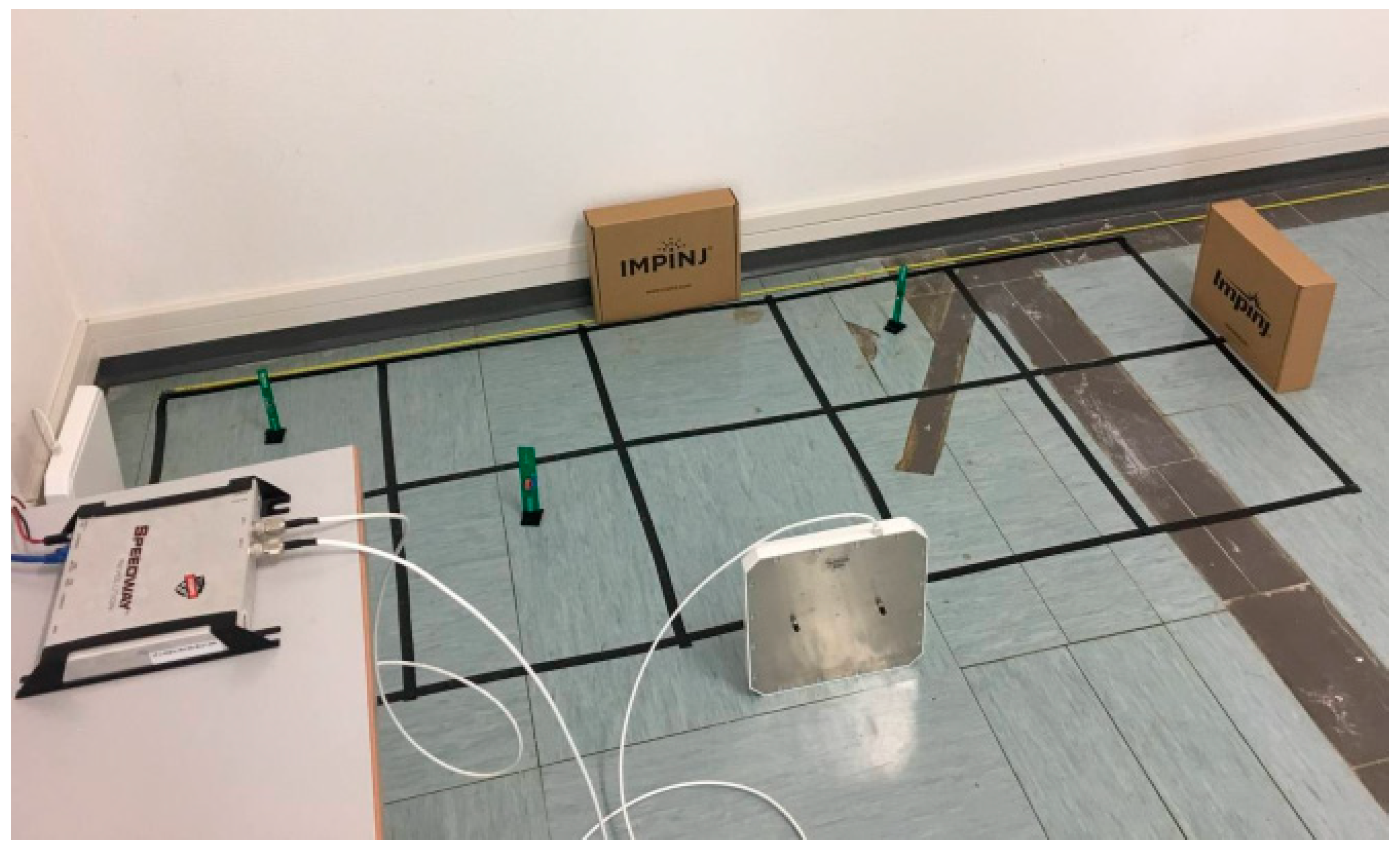
Preliminary tests have been organized in the university laboratory, in order to monitor sensors’ detection and communications. The reader that has been chosen is the Speedway from Impinj [
29], which is a high-performance RAIN RFID fixed reader that delivers the flexibility and reliability necessary to provide effective item visibility. As a laboratory test, the required radiation power that was necessary was not very high, but without lack of generality, the test can be extended also to larger distances by choosing a more powerful reader. As shown in
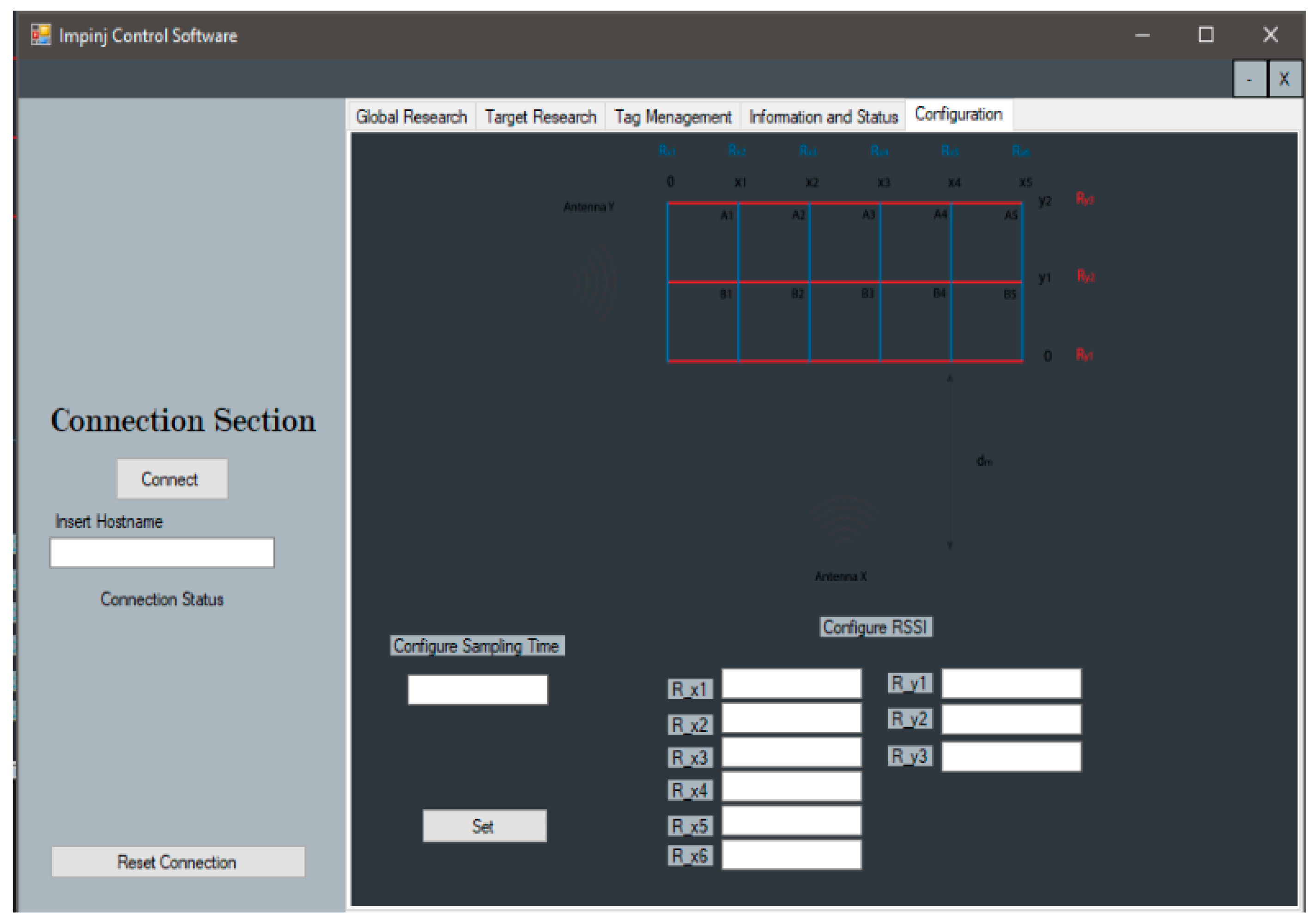
Figure 10, two antennas have been used and some sensors have been placed on the floor, where a location grid has been drawn, simulating the effects of the multifunctional panels. When the reader is activated, it can be managed by the console shown in
Figure 11; the average RSSI is calculated on the reference line and the distance is computed as a consequence by means of the code sections reported in
Figure 12. Considering the test structure of
Figure 10, no transmission faults have been observed. The computed distances demonstrate an average relative error of about 5%, with respect to the real ones. In
Figure 13, an example is reported, illustrating the measured distance as a function of the RSSI.
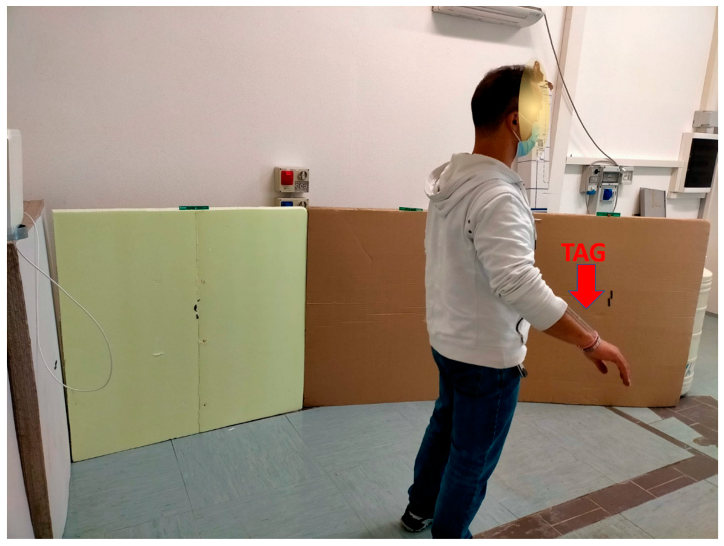
Further tests with an operator in the dedicated room have also been conducted, in order to simulate possible operations in a real plant. The operator is provided a passive TAG, installed on his wrist (
Figure 14); moving through this environment, the MULTIFID panels have correctly detected and tracked his position. Some measured results are reported in
Table 1, confirming the already achieved results obtained in the first setup.
A global search measurement approach has been implemented for distance measurement. The reader interrogates the tags for a fixed time and create a list of acknowledgements. Each antenna creates its own list, and there is a check to individuate and detect remote multiple readings of the same tag. The lists are then merged and, considering the RSSI, the tag distance is evaluated. Finally, the database is invoked to verify if the considered tag has been already registered. In case of a positive request, the tag name is provided as output, or otherwise it is classified as Unknown.
Regarding the sensors’ measurements, the proposed MULTIFID panel displays temperature and moisture levels close to those obtained with dedicated instruments or independent sensors, as shown in
Figure 5. The uncertainties are around 3%, thus, quite compatible with the needs of the considered application.
5. Conclusions
The described work proposes an innovative system based on a sensorial multifunctional panel for smart factory application. Innovation on both building and electronic fields are proposed to allow the obtaining of several benefits. From a structural perspective, the proposed panel allows for the improving of the thermal resistance of a building, and facilitates the installation of electronic systems. While considering the advantages of electronics, the proposed system allows for the monitoring of the environmental characteristics of the envelop, to achieve better durability and efficiency, and for the controlling of the movements of operators, ensuring a safe sharing of the working environment. Notably, more research can be conducted concerning the sensors’ integration and detection algorithms. In addition, the MULTIFId panel has the potential to be applied among several fields and applications, as it embeds suitable electronics, and the provided data can be easily managed remotely for different uses. Close fields include, for instance, the industrial internet of things (IIoT), Internet of Services (IoS), and machine learning.
Author Contributions
Conceptualization, V.S.; methodology, F.C.; investigation, T.G.; data curation, L.P., M.R. and A.L.; writing—original draft preparation, L.P. and M.R.; writing—review and editing, L.P., V.S. and M.R.; supervision, T.G.; project administration, F.F.D., L.M., P.D.B. and V.S. All authors have read and agreed to the published version of the manuscript.
Funding
This research has been funded by the “MULTIFId” Project, Fund for Sustainable Growth, Intelligent Factory Desk, D.M. 5 March 2018Chapter III. Subjects involved: 2Bite S.r.l., Pack System S.r.l., University of L’Aquila as consultants (Department DIIIE and DICEAA).
Acknowledgments
Authors thank: Giovanni Schettini (University of L’Aquila) for the support in the test system realization; Antonello Cucchiella (Pack) for the support in the Hot Bot realization; and the technicians of the electronic laboratory of the University of L’Aquila, Stefano Ricci and Andrea Pelliccione, for their precious support during the prototype’s implementation and preliminary measurements.
Conflicts of Interest
The authors declare no conflict of interest.
References
- Chen, B.; Wan, J.; Shu, L.; Li, P.; Mukherjee, M.; Yin, B. Smart Factory of Industry 4.0: Key Technologies, Application Case, and Challenges. IEEE Access 2018, 6, 6505–6519. [Google Scholar] [CrossRef]
- Ferrari, P.; Flammini, A.; Rinaldi, S.; Sisinni, E.; Maffei, D.; Malara, M. Impact of Quality of Service on Cloud Based Industrial IoT Applications with OPC UA. Electronics 2018, 7, 109. [Google Scholar] [CrossRef] [Green Version]
- Raposo, D.; Rodrigues, A.; Sinche, S.; Silva, J.S.; Boavida, F. Industrial IoT Monitoring: Technologies and Architecture Proposal. Sensors 2018, 18, 3568. [Google Scholar] [CrossRef] [PubMed] [Green Version]
- Salhaoui, M.; Guerrero-González, A.; Arioua, M.; Ortiz, F.J.; El Oualkadi, A.; Torregrosa, C.L. Smart Industrial IoT Monitoring and Control System Based on UAV and Cloud Computing Applied to a Concrete Plant. Sensors 2019, 19, 3316. [Google Scholar] [CrossRef] [Green Version]
- Available online: https://www.fabbricaintelligente.it/wp-content/uploads/2018/04/Roadmap-Fabbrica-Intelligente-.pdf (accessed on 15 April 2021).
- Valero, E.; Adán, A.; Cerrada, C. Evolution of RFID Applications in Construction: A Literature Review. Sensors 2015, 15, 15988–16008. [Google Scholar] [CrossRef] [PubMed] [Green Version]
- Stojanović, G.; Radovanović, M.; Malešev, M.; Radonjanin, V. Monitoring of Water Content in Building Materials Using a Wireless Passive Sensor. Sensors 2010, 10, 4270–4280. [Google Scholar] [CrossRef] [PubMed] [Green Version]
- Rotilio, M.; Pantoli, L.; Muttillo, M.; Annibaldi, V. Performance Monitoring of Wood Construction Materials by Means of Integrated Sensors. Key Eng. Mater. 2018, 792, 195–199. [Google Scholar] [CrossRef]
- Ding, L.; Zhou, C.; Deng, Q.; Luo, H.; Ye, X.; Ni, Y.; Guo, P. Real-time safety early warning system for cross passage construction in Yangtze Riverbed Metro Tunnel based on the internet of things. Autom. Constr. 2013, 36, 25–37. [Google Scholar] [CrossRef]
- Fu, Y.; Hoang, T.; Mechitov, K.; Kim, J.R.; Zhang, D.; Spencer, J.B.F. Sudden Event Monitoring of Civil Infrastructure Using Demand-Based Wireless Smart Sensors. Sensors 2018, 18, 4480. [Google Scholar] [CrossRef] [PubMed] [Green Version]
- Rafsanjani, H.N.; Ahn, C.R.; Alahmad, M. A Review of Approaches for Sensing, Understanding, and Improving Occupancy-Related Energy-Use Behaviors in Commercial Buildings. Energies 2015, 8, 10996–11029. [Google Scholar] [CrossRef] [Green Version]
- Barile, G.; Leoni, A.; Pantoli, L.; Stornelli, V. Real-Time Autonomous System for Structural and Environmental Monitoring of Dynamic Events. Electronics 2018, 7, 420. [Google Scholar] [CrossRef] [Green Version]
- Coulby, G.; Clear, A.; Jones, O.; Godfrey, A. A Scoping Review of Technological Approaches to Environmental Monitoring. Int. J. Environ. Res. Public Health 2020, 17, 3995. [Google Scholar] [CrossRef]
- Xie, B.; Li, J.; Zhao, X. Research on Damage Detection of a 3D Steel Frame Model Using Smartphones. Sensors 2019, 19, 745. [Google Scholar] [CrossRef] [PubMed] [Green Version]
- Itkin, M.; Kim, M.; Park, Y. Development of Cloud-Based UAV Monitoring and Management System. Sensors 2016, 16, 1913. [Google Scholar] [CrossRef] [PubMed]
- Ferrández-Pastor, F.J.; García-Chamizo, J.M.; Nieto-Hidalgo, M.; Pascual, J.M.M.; Mora-Martínez, J. Developing Ubiquitous Sensor Network Platform Using Internet of Things: Application in Precision Agriculture. Sensors 2016, 16, 1141. [Google Scholar] [CrossRef] [Green Version]
- Saqib, M.; Almohamad, T.A.; Mehmood, R.M. A Low-Cost Information Monitoring System for Smart Farming Applications. Sensors 2020, 20, 2367. [Google Scholar] [CrossRef] [PubMed] [Green Version]
- Yang, J.; Zhou, J.; Lv, Z.; Wei, W.; Song, H. A Real-Time Monitoring System of Industry Carbon Monoxide Based on Wireless Sensor Networks. Sensors 2015, 15, 29535–29546. [Google Scholar] [CrossRef] [Green Version]
- Takabayashi, K.; Tanaka, H.; Sakakibara, K. Toward an Advanced Human Monitoring System Based on a Smart Body Area Network for Industry Use. Electronics 2021, 10, 688. [Google Scholar] [CrossRef]
- Fontes, F.; Antão, R.; Mota, A.; Pedreiras, P. Improving the Ambient Temperature Control Performance in Smart Homes and Buildings. Sensors 2021, 21, 423. [Google Scholar] [CrossRef]
- UNI EN ISO 6946. Building Components and Building Elements—Thermal Resistance and Thermal Transmittance—Calculation Method; International Standard Organization: Geneva, Switzerland, 2018. [Google Scholar]
- UNI ISO 9869:1994. Thermal Insulation—Building Elements—In-Situ Measurement of Thermal Resistance and Thermal Transmittance; ISO: Geneva, Switzerland, 1994. [Google Scholar]
- UNI 10351:2015. Building Materials and Products, Hygrothermal Properties, Procedure for Determining the Design Values; CTI: Milan, Italy, 2015. [Google Scholar]
- Distefano, D.L.; Gagliano, A.; Naboni, E.; Sapienza, V.; Timpanaro, N. Thermophysical characterization of a cardboard emergency kit-house. Math. Model. Eng. Probl. 2018, 5, 168–174. [Google Scholar] [CrossRef] [Green Version]
- Available online: https://www.archicart.com/pannelli.html (accessed on 15 April 2021).
- Pantoli, L.; Leoni, A.; Stornelli, V.; Ferri, G. An IC architecture for rf energy harvesting systems. J. Commun. Softw. Syst. 2017, 13, 96–100. [Google Scholar] [CrossRef] [Green Version]
- di Marco, P.; Leoni, A.; Pantoli, L.; Stornelli, V.; Ferri, G. Remote Sensor Networks with Efficient Energy Harvesting Architecture. In Proceedings of the 2016 12th Conference on Ph.D. Research in Microelectronics and Electronics (PRIME), Lisbon, Portugal, 27–30 June 2016; pp. 1–4. [Google Scholar] [CrossRef]
- Farsens Website. Available online: www.farsens.com (accessed on 15 April 2021).
- Impinj Website. Available online: www.impinj.com (accessed on 15 April 2021).
| Publisher’s Note: MDPI stays neutral with regard to jurisdictional claims in published maps and institutional affiliations. |
© 2021 by the authors. Licensee MDPI, Basel, Switzerland. This article is an open access article distributed under the terms and conditions of the Creative Commons Attribution (CC BY) license (https://creativecommons.org/licenses/by/4.0/).


 ,
, 


