1. Introduction
Nuclear magnetic resonance (NMR) technology is a spectrum measurement method, which is widely used in the fields of biomedicine and materials science [
1]. However, the signal sensitivity is very low due to the small gyromagnetic ratio of nuclei such as
1H and
13C which hinders its further development and applications. Dynamic nuclear polarization (DNP) enhancement technology provides an effective solution to improve the sensitivity of NMR. Using DNP-NMR technology, irradiation of the THz wave on sample, due to the magnetic moment of electron is 660 times that of the
1H nuclei, THz wave irradiation can enhance the electron spin polarization, electronic polarization can be easily transferred to adjacent
1H nuclei, improve NMR signal sensitivity, able to reduce the original week’s analysis time to a few minutes [
2,
3]. To obtain high-resolution spectra, modern NMR spectroscopy requires extremely high magnetic fields, thereby requiring the further development of electromagnetic (EM) wave sources used in DNP technology are correspondingly increased from millimeter to terahertz (THz) frequency bands. Vacuum electron devices (VEDs) such as gyrotrons and extended interaction klystrons (EIKs) can stably generate high-power continuous waves in the THz band [
4,
5,
6]. Below 500 GHz, gyrotrons and EIKs are excellent electromagnetic sources for DNP-NMR. In order to eliminate the magnetic field interference between the THz wave source and the NMR spectrometer, they should be several meters apart. Therefore, THz transmission system proves to be a key factor for the successful application of the whole DNP-NMR system. At present, there are two kinds of transmission systems, i.e., quasi-optical transmission system and overmoded waveguide transmission system.
The free space quasi-optical beaming technique utilizes a series of lenses or mirrors to support the low loss propagation of Gaussian-like beam, but it is difficult to align stably and safely [
1]. The most convenient method is using waveguides, including dielectric waveguides [
7,
8], corrugated metallic waveguides [
9], metallic wires [
10], and dielectric- lined metallic waveguides [
11]. The high-order mode generated by the THz wave source is converted into the low-order circular waveguide TE
11 mode through the mode converter. However, the ohmic loss of the TE
11 mode is dramatically high in the THz band, and it is necessary to convert the basic circular waveguide TE
11 mode into a low-loss mode (TEM
00 or HE
11) to facilitate subsequent transmission [
9,
12]. A smooth profiled horn was proposed for easily manufacturing in [
13] and successfully produced a Gaussian beam. Nonetheless, the converted electric field is slightly elliptical. Corrugated mode converter can efficiently transform a fundamental circular waveguide mode into the hybridHE
11 mode, which is prevalently utilized in plasma physics [
14], radio astronomy [
15] and satellite communications [
16], so a corrugated TE
11-HE
11 mode converter is proposed to meet the requirement of DNP-NMR transmission.
Furthermore, monitoring the EM wave power stability and magnitude in real-time is necessary, because the NMR spectrometer requirements on EM wave purity and stability are strict. However, measuring the THz wave source and the EM wave power in the transmission line directly is too difficult, thereby necessitating the extraction of a part of the wave energy for the ease of measurement.
The directional coupler is widely used in the transmission line for power extraction. In a low-frequency transmission system, it is accomplished by a small coupling hole. Due to the requirements of low heat dissipation and high-power capacity in practical applications, a linear coupling holes array was proposed for the 140 GHz transmission line in Frascati-Tokamak [
17]. However, when the transmitted mode is the HE
11 hybrid mode, the power extracted by the linear holes array will be unstable. To improve the coupling stability, a quartz beam splitter was proposed to accomplish the coupling function in the 250 GHz transmission line [
18]. Whereas the narrowband operation limits the performance of the quartz beam splitter for signal coupling. The metal cylindrical wire array is a potential candidate to accomplish the broadband and stability directional coupling in THz frequency. For the HE
11 mode whose polarization direction is perpendicular to the cylindrical wire array plane, most of the waves can go across the plane and maintain their original propagation direction. For the parallel one, most of the waves are reflected. A three-port directional coupler is designed based on the cylindrical wire array and the overmoded corrugated waveguide theory in this paper. The designed three-port directional coupler can steadily extract a part of energy in a wide frequency range of 300–360 GHz.
From the DNP-NMR system shown in
Figure 1, in which 500 MHz is the resonance frequency of NMR instruments, 330 GHz is the frequency of EM waves generated from the THz wave source (
Figure 1 ①) and irradiated on the sample (
Figure 1 ⑥). The transmission system designed in this paper is aimed to transmit 330 GHz EM waves generated by THz source to the NMR spectrometer which includes a TE
11-HE
11 converter, corrugated waveguide, three-port directional coupler, and 90° miter bend. The mode converter and three-port directional coupler can be easily combined by the well-developed corrugated waveguide technology. The mode converter can generate pure HE
11 mode, and then the HE
11 mode will be transmitted by the low loss metal circular corrugated waveguide. A 90° miter bend can change the direction of EM wave propagation at the corner. A direction coupler extracts approximately −33 dB power in real-time to monitor the whole energy in the transmission.
2. TE11-HE11 Corrugated Mode Converter
In our design, the input mode is TE
11 mode, and the ideal output mode is HE
11 mode which consists of 85% TE
11 mode and 15% TM
11 mode by the power ratio. As shown in
Figure 2, the corrugated horn is carved with several equally spaced corrugated slots on the inner surface of the horn, and the curved contour of the horn is sin
2 type. Compared with other profiles such as the linear type, sin
2 profile can maintain a lower reflection over a wide frequency range [
19].
The purity of the output mode is controlled by several parameters, such as the radii of the input and output waveguides, the depth, width, and period of the slot. The depth of the slot decreases with the increase of the horn radius and remains constant in the end. The horn’s radius
a(
z) is expressed in (1) [
14], where
z is the coordinate axis,
ai is the input radius of the horn,
ao is the output radius of the horn,
L is the total length of the horn, and
A is a parameter that affects the similarity between the horn profile and
sin2; the smaller
A is, the more the horn profile curve tends to be
sin2 shape.
The input diameter of the mode converter is identical to the standard diameter of the fundamental circular waveguide. The input radius is around
), where
c is the light speed. At the same time, it should be consistent with the output window of the THz wave source. The output radius is connected to the overmoded waveguide by a tapered horn. The parameter
A is around 0.2. The length
L of the horn is around
, where
is the wavelength at the operating frequency. There are
N corrugated slot periods in the whole inner wall of the horn, so the length of
L should be an integer multiple of the period, i.e.,
L =
Np. The parameter
p is the corrugated slot period which is around
. The width of the corrugated slot is
t, and
is the ratio of the width of the corrugated slot to the period
p, which is around 0.8. The slot depth along the horn is a critical parameter for horn performance [
20].
The first corrugated slot depth is
, then the slot depth decreases to
through
Nc cycles, with the number of
Nc between 5–12. This section is called the mode conversion or impedance conversion area in which the output TM
11 mode will be mixed with TE
11 mode to form HE
11 mode. After the mode conversion zone, the depth of the slot needs to introduce a correction factor so the slot depth is given by (2), where
dj is the depth of the
j-th slot, which varies with the horn radius
aj,
λ is the wavelength,
k is wavenumber at the operating frequency,
aj is the radius at the
j-th slot.
For the 330 GHz corrugated mode converter, the input radius
ai = 0.43 mm, output radius
ao = 2. Therefore, only five parameters, including
N (
L =
Np),
A,
Nc,
p, and
(
, need to be optimized.
N and
Nc are set in 55–75 and 5–12, respectively. The ranges of
A and
are set as 0.2–0.4 and 0.6–0.9, respectively.
p is set as 0.15–0.25. The optimization is aimed at constraining the power ratio of TE
11 mode and TM
11 mode close to 85/15 (≈ 5.7) to mix HE
11 mode at the output port and reduce the reflection of the TE
11 at the input port. Therefore, cost functions are used in the optimization and is expressed by Equation (3):
where
f values are the discrete frequency points in the desired frequency range (300–360 GHz),
M is the number of the frequency sample points.
and
are the TE and TM mode magnitude at the output port, respectively. Next, we need to find out the vector
to minimize the cost function
, namely:
The final values of the parameters after the optimization are shown in
Table 1.
The
S11 parameter means the reflection of the TE
11 mode on port 1. As shown in
Figure 3, the
S11 parameter is less than −25 dB at the range of 300–360 GHz, which shows good transmission characteristics of the horn. The
S11 parameter can be as low as –26.6 dB at 330 GHz.
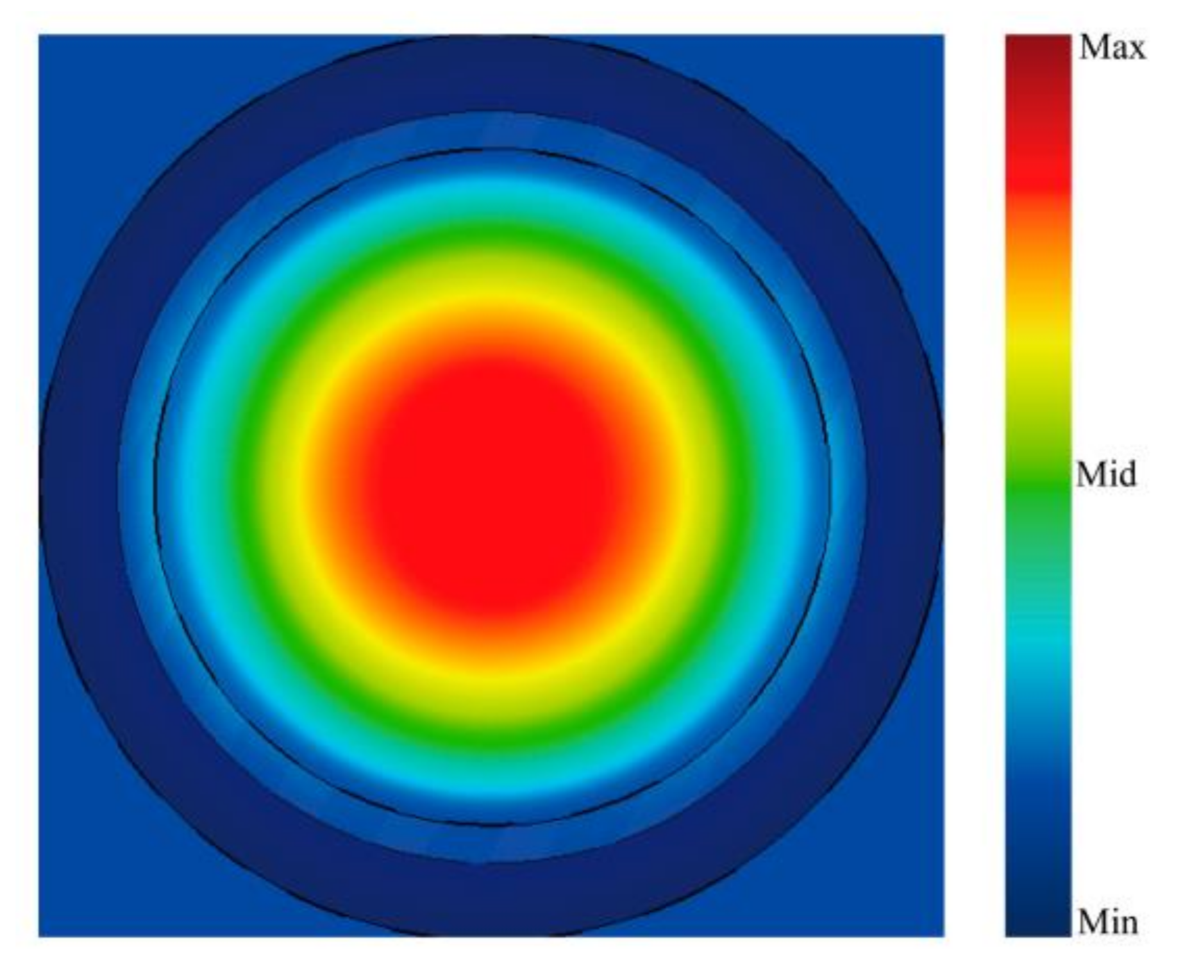
Figure 4 shows the simulated profile of the electric field at the output port, which is closed to the HE
11 basic mode in the circular corrugated waveguide. As shown in
Figure 5, the TE
11 mode gradually shapes into HE
11 mode while traveling through the horn. At the output port and the operation frequency 330 GHz, the power ratio of TE
11 and TM
11 is 6.72. The value of the electric field integral in
x,
y and
z directions are 0.029395, 0.00023821, and 0.0032955, respectively, and the ratio of the electric field in the direction of
x polarization is 98.8% at 330 GHz, which can maintain good linear polarization characteristics.
The corrugated horn is an excellent mode converter, which can effectively convert the single mode in the metal waveguide into the HE11 mode. These excellent characteristics can be mainly attributed to two facts. First, the corrugated horn can realize the TM and TE modes with same phase velocity transmission so that the same phase relationship can be maintained at different frequencies, which greatly expands the working bandwidth of the corrugated horn. Second, the slot depth has a good inhibitory effect on the longitudinal current in the horn, and the electric field near the slot is sharply weakened.
3. Cylindrical Wire Array Theory and Three-Port Directional Coupler
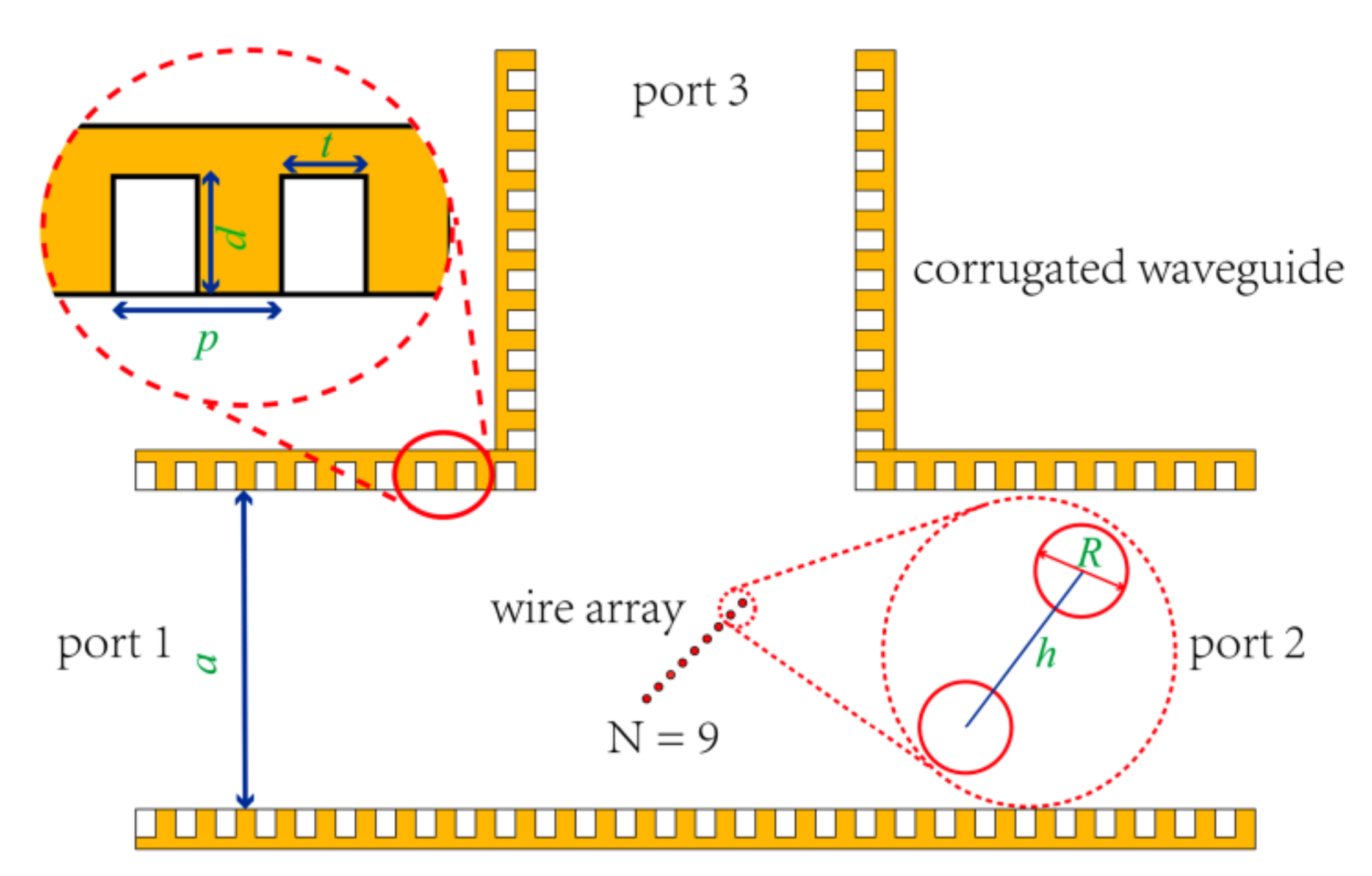
By combining the corrugated waveguide and the cylindrical wire array theories, we designed a three-port directional coupler for the 330 GHz/500 MHz DNP-NMR transmission line. The designed three-port directional coupler is composed of a corrugated waveguide and a cylindrical wire array which is placed in the middle of the corrugated waveguide diagonal. From the 3D structure shown in
Figure 6, the EM waves are fed from the port 1 split into two parts out of ports 2 and 3. All the three-port directional coupler structural parameters are shown in the sectional view by
Figure 7, where
a,
p,
t, and
d are the diameter, corrugated slot period, width of the corrugated slot, and depth of the corrugated slot, respectively;
N,
R, and
h are the cylindrical wire number, cylindrical wire diameter and period of the cylindrical wire array, respectively.
For the three-port directional coupler, there are three important design indicators, i.e., (1) extraction approximately 0.05% EM wave power on port 3 stably, which can be used to measure the EM wave power of the transmission line in real-time; (2) as much EM wave as possible output at port 2, so as not to affect the power of the EM wave transmitted to the NMR spectrometer. This requires port 1 to have a very small reflection, with an ideal value of 0, and to transmit as much power to port 2 as possible, with an ideal value of 1–0.05%; (3) to make the directivity value of the three-port directional coupler larger, when the input port is port 2, as much power as possible should be output at port 1, with an ideal value of 1, and no power should be coupled out at port 3, with an ideal value of 0. To sum up, the ideally designed objective of
S-matrix at 330 GHz is:
where the performance of this three-port directional coupler is independent of the parameter
S13,
S23, and
S33.
For the corrugated waveguide, if the following conditions are met, i.e., (1) the diameter
a is much larger than
(the wavelength at the operating frequency); (2) the corrugated slot depth and period are approximately
and
, respectively; (3)
t/
p > 0.5, the field distribution in the waveguide can satisfy the equilibrium condition. Besides, the transmitted eigenmode is the HE
11 mode with the linear polarization. The expression of the inner electric field distribution of the waveguide with a circular cross-section can be simplified as follows:
where
is the zeroth-order Bessel function;
,
, and
are the components of the electric field in the
x,
y, and
z directions;
is the magnitude of the electric field;
is the radial coordinate. When the operating frequency is 330 GHz,
a,
p,
t, and
d are 19, 0.32, 0.16, and 0.23 mm, respectively [
21].
A metal cylindrical wire array was introduced to coupling the propagating HE11 mode to the waveguide since the cylindrical wire array has different reflection and transmission coefficients for HE11 mode with different polarization, which is determined by the period of the cylindrical wire array and the radius.
As shown in
Figure 8, assuming that the cylindrical wire array has an infinite number of periods along the x direction, and simultaneously, the length of the metal cylinder extends indefinitely along the
z-axis, the incident direction of the Gaussian beam is at an angle of
to the
x-axis. Besides,
l is
l-th metal cylinder. The Gaussian beam and HE
11 mode coupling efficiency can be as high as 98% [
22]. Moreover, by Fourier transform and Gaussian integration, the expression of the Gaussian beam can be expended using the superposition of a series of plane waves. The total scattering electric field of each plane wave on the cylindrical wire array can be calculated from the single-cylinder scattering electric field.
The transmission coefficient T and reflection coefficient R of the power can be calculated by Equations (7) and (8), where
and
are the wave number of Gaussian beam and the component in the
y direction,
and
are the wave number in
x and
y direction of
m-th space harmonic,
is the harmonic coefficient of the
l-th cylindrical scattering field:
when the angle of EM wave direction of propagation and cylindrical wire array plane is 45°, the electric field distribution of two different linear polarization electromagnetic waves shown in
Figure 9,
Figure 10 and
Figure 11 show the curves of the transmission coefficient (T) and reflection coefficient (R) varying with the diameter of the cylindrical wire and the period of the wire array respectively, which are obtained by using the above theory in MATLAB when the Gaussian fundamental mode with the polarization direction is perpendicular to the wire array plane, therefore, the incident angle is 45° and the frequency is 330 GHz. It can be seen that it is highly consistent with the results obtained by two-dimensional simulation in COMSOL Multiphysics. The transmission coefficient (T) decreases with the increase of diameter and increases with the increase of period
h, while the reflection coefficient is opposite to this.
After optimization, the period of the wire array
h is 0.3 mm, and the diameter of each cylindrical wire
R is 90 μm; as shown in
Figure 12, in the frequency range from 300 to 360 GHz, the transmission coefficient T (
S21) is approximately 0.99, the reflection coefficient R (
S31) can be less than 0.0125. At 330 GHz, the transmission coefficient T is 0.989, and the reflection coefficient R is 0.011.
As shown in
Figure 13, parameter sweeping is employed with respect to the number of cylindrical wires. Our design goal is to couple a small amount of power without affecting the main transmission line. Only nine metal cylinders are required to be placed in the center of the diagonal, and the reflection coefficient R is 0.00586 at 330 GHz.
We modeled and simulated the three-port directional coupler in CST Studio to verify the performance. The HE
11 mode can be excited by mixing 85% circular waveguide TE
11 mode and 15% TM
11 mode together. High-purity linear polarization is required in the NMR spectrometer. For the main beam transmitted in the transmission line (HE
11 mode wave polarization direction is perpendicular to the cylindrical wire array plane),
S11,
S21, and
S31 parameters are shown in
Figure 14;
S12,
S22, and
S32 parameters can be obtained by converting the input port. At 330 GHz, the
S11 parameter can reach up to −41 dB, and keep below −20 dB in the 300–360 GHz frequency range; a small part of energy output at port 3, most of the energy continues transmitting. At 330 GHz, they are −33.2 dB and −0.064, respectively, as shown in
Figure 14. The coupling coefficient can remain stable in the 300–360 GHz frequency band. By setting the power value detector on port 3, the EM wave power in the transmission line can be measured in real-time. An important parameter of a directional coupler is directivity. For a three-port directional coupler, the difference in dB of the output power P3 (the power output on port 3 by port 1 input) and P3* (the power output on port 3 by port 2 input) is called directivity. The directivity of the designed three-port directional coupler is shown in
Figure 15. It indicates that at 330 GHz, the directivity can reach 11.8 dB.
In order to verify the integrity of the system as shown in
Figure 1, a 90° bend waveguide with the same structure as the three-port directional coupler is designed. There are many design schemes for 90° miter bend, such as the principle of conversion optics and the surface plasmon polaritons [
23,
24]. The simplest method to realize the 90° miter bend is to directly reflect the EM wave by using the metal mirror. It has a wide working frequency band, so it is widely used in practice [
25]. However, these methods do not consider the influence on the polarization direction of the propagation mode. In this paper, we simply verify a 90° miter bend based on the different reflection coefficients (R) of the electromagnetic wave with different polarization directions.
There are two differences with the three-port directional coupler, i.e., (1) as shown in
Figure 9a, for the HE
11 mode whose polarization direction is perpendicular to the cylindrical wire array plane, most of the waves can go through the wire array and maintain their original propagation direction. For the parallel one, most of the waves are reflected as shown in
Figure 9b. The electric field polarization of the incident EM wave of the three-port directional coupler is perpendicular to the wire array, while the electric field polarization of the incident electromagnetic wave of the designed 90° miter bend is parallel to the wire array plane; (2) to get the maximum power output, the number of period of the wire array is 70 to cover the whole diagonal of the waveguide (
a = 19 mm,
h = 0.3 mm,
R = 90 μm), while the three-port directional coupler N = 9.
Since most of the energy will be coupled out at the port 3, the direction of EM wave propagation can turn 90°. Therefore, this structure can achieve the function of 90° miter bend. As the result shown in
Figure 16, the
S11 parameter can be less than ‒50 dB at the frequency of 300–360 GHz, the
S31 parameter can be larger than ‒0.15 dB. Although the
S21 parameter is not ideal, subsequent work can be done to redesign the period and diameter of the wire array used in 90° bend to achieve less energy loss. In addition to changing the direction of EM wave propagation, the structure can also further improve the purity of linear polarization of the system by filtering the vertical EM waves.


