1. Introduction
A microgrid is a group of interconnected loads and distributed energy sources as a single controllable entity with respect to the grid, used for power generation and energy storage. Its applications range from supplying a few hundred kilowatts to several hundred megawatts. A microgrid enables service providers and consumers to eliminate dependency on centralized energy generation [
1,
2]. Microgrids are growing very fast because of their cost effectiveness, reliability, ease of implementation, and integration of multiple sources of power generation methods. Solar photovoltaic systems offer advantages such as infinite energy sources, low maintenance costs, and most of all zero carbon emission characteristics [
3,
4]. Solar microgrids have been utilized extensively to augment grid power [
5,
6,
7]. Simulation of a hybrid solar/wind microgrid has been performed [
8].
The rapid growth of renewable energy sources, energy storage, and power semiconductor devices is dramatically changing the nature of the transmission, distribution, and utilization of electrical energy. Most of the renewable energy sources provide DC power. Modern loads, such as lighting, electric vehicles, data centers, or variable frequency drives, require DC power. Energy storage systems (ESS) such as batteries and capacitors are in DC as well. Compared with an AC microgrid, a DC microgrid has fewer power conversion stages; therefore, the structure, control, and power management of a DC microgrid are simpler, resulting in higher overall efficiency and system stability [
9]. Extensive research is being conducted on control and power management for DC microgrids with applications in electric vehicle charging [
10,
11,
12,
13], lighting [
14], and DC homes [
15]. Novel control strategies were developed to improve load sharing, voltage, and power stability at different load demands [
16,
17,
18,
19,
20]. Topologies and control of DC-DC converters, such as bidirectional converters and soft switching, were widely studied to meet the application of DC microgrids [
21,
22]. The control strategies of energy storage systems were investigated to maintain the power balance in the microgrid [
23]. A DC microgrid was optimized, simulated, and evaluated at the system level [
24].
Recent advances in control architecture and communication technologies have enabled smart cyber-physical systems (CPS) to meet the emerging needs of renewable energy, microgrids, electric vehicles, and internet of things (IoT) [
25]. A power cyber-physical system includes a network of heterogeneous energy sources and loads to form the physical layer, and sensors, communication networks, control systems, and supervisory control and data acquisition system (SCADA) to form the cyber layer. As modern energy systems are becoming more complex and requiring higher intelligence, their proper operation relies heavily on the cyber layer for data acquisition, processing, and transmission [
26]. Recent deployment of smart metering infrastructure and emerging information communication technologies require an even more advanced monitoring and remote-control capability for power systems.
The fast progress of microgrids, costs, and space requirements have created special challenges for establishing microgrid laboratories for many academic institutions [
27]. Although the current curriculum includes the classic power system, communication, computing, and control to study the modern microgrids, the components are scattered in different courses across different disciplines. Literature shows the current educational microgrid laboratories are mostly implemented by simulation or emulation [
8,
28]. Furthermore, conventional power electronics were usually built without the cyber layer. It is the integration with the cyber layer that creates smart power solutions. A laboratory scale solar microgrid CPS creates a centralized platform for teaching renewable energy systems to educate future workforces.
In this paper, a smart solar microgrid CPS that integrated hardware components and software packages is presented to integrate cutting edge microgrid technologies into an enabling teaching tool for the engineering technology curriculum. The CPS was built on a solar panel controlled by a maximum power point tracking (MPPT) charge controller. The MTTP charge controller extracted the maximum amount of power from the solar panel and stored the excessive energy in a Li-ion rechargeable battery. The output power from the MTTP charge controller supplied power to LED lights and wirelessly charged a toy electric vehicle. A DC-DC converter was used to power the devices that require a different voltage. A microcontroller was used to control the loads; conduct data acquisition on the solar panel, battery, and load; and transfer data to a cloud database for further analysis. The physical layer, including the solar panel, battery, charge controller, and loads, was integrated with the cyber layer, which consists of the sensors, communication networks, SCADA, and control systems. The solar power CPS was built in a portable laboratory scale. It has been used in junior/senior level courses to teach topics including microcontrollers, battery charging, MPPT, data acquisition, and software programming.
The paper is organized as follows.
Section 2 describes the system design. Data acquisition and process are detailed in
Section 3. Programming logic and GUI design are presented in
Section 4.
Section 5 describes the pedagogical approach. Experimental results on the microgrid are presented in
Section 6. Educational assessment results are reported in
Section 7. Finally, the conclusion is provided in the last section.
2. Solar Microgrid Cyber-Physical System Design
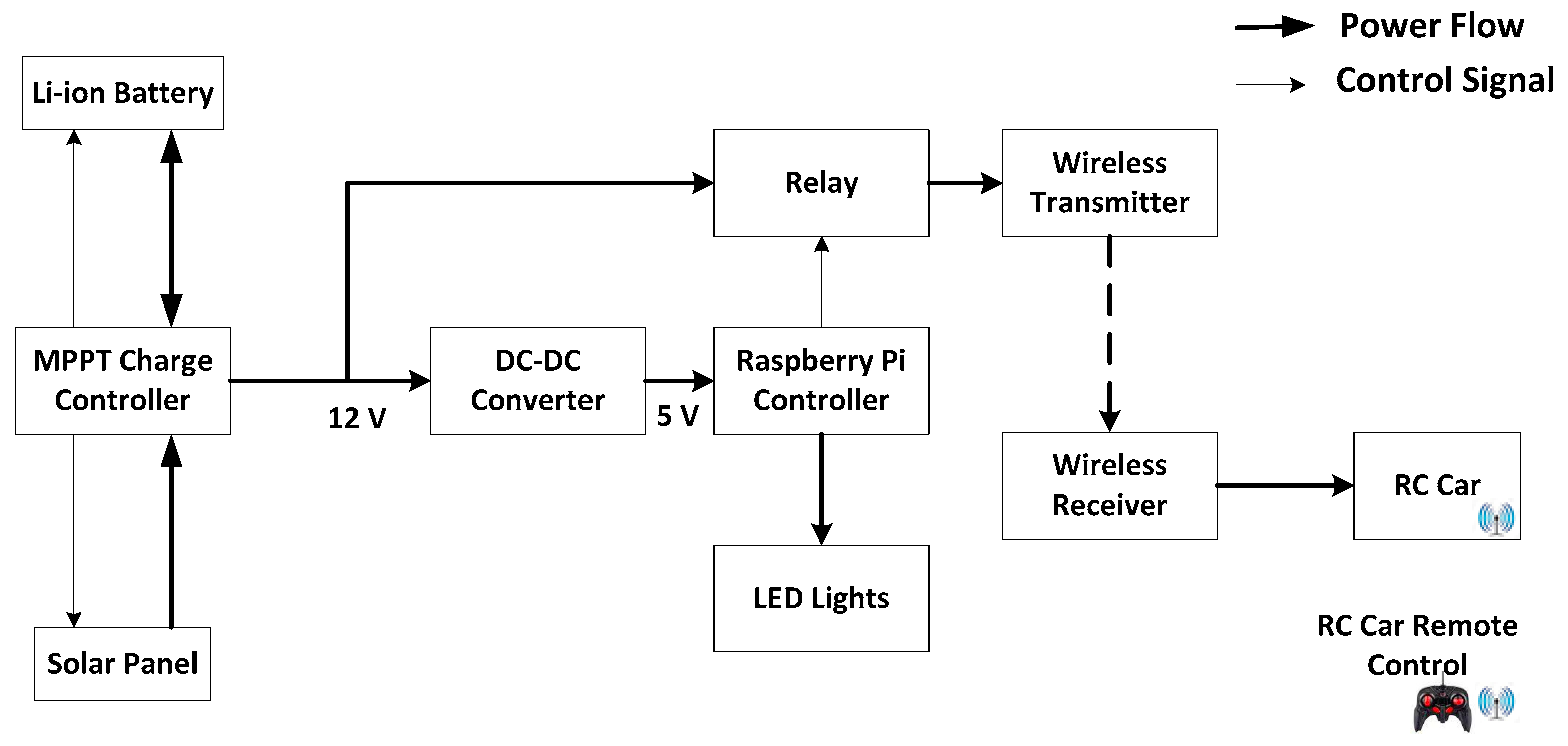
The solar microgrid cyber-physical system is composed of a solar panel, a microcontroller, a maximum power point tracking (MPPT) charge controller, a Li-ion battery, and loads. The solar panel has an output voltage of 18 V and output power of 40 W. The Li-ion battery rated at 12 V and 42 Ah provides energy storage for the system. Li-ion batteries were chosen because they operate over a wider temperature range with higher energy densities compared with NiCd batteries.
Figure 1 shows the system connection. The solar panel is connected to the input of the charge controller, and the output of the charge controller is connected to the battery and loads. If the solar panel is able to provide enough power to the loads, the charge controller will charge the battery if the battery is not fully charged. On the other hand, if the solar panel is not able to provide enough power to the loads, the charge controller will discharge the battery, and provide power to the loads from both the solar panel and the battery.
A ProStar MPPT charge controller manages the power flow among the solar panel, the battery and the load. It uses a smart tracking algorithm that finds and maintains operation at the solar panel’s peak power point to maximize energy harvest. The charge controller provides seven standard battery charging settings that are selected with the settings switches. These standard charging settings are suitable for Li-ion batteries and lead–acid batteries ranging from sealed (gel, AGM, maintenance-free) to Flooded and L-16 cells.
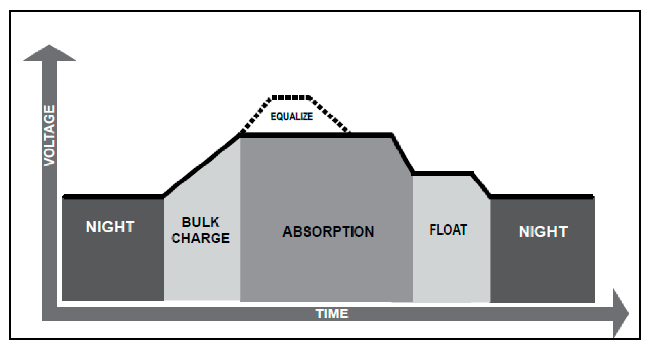
The MPPT charge controller has a four-stage battery charging algorithm for fast, efficient, and safe battery charging. In the bulk charge stage, the battery is not fully charged. The controller will deliver all the available solar power to charge the battery. When the battery will have charged to the absorption voltage setpoint, the charge controller will operate in the absorption stage. In this stage, constant voltage regulation is used to maintain battery voltage at the setpoint. The battery must remain in this stage for a cumulative 150–180 min, depending on the battery type. After the battery is fully charged, the charge controller reduces the battery voltage to the float voltage setpoint. The float stage provides a very low rate of maintenance charge. Once in the float stage, loads can draw power from the battery. If the loads exceed the solar charge current, the controller can no longer maintain the battery at the float setpoint. When the battery voltage drops below the float setpoint for a cumulative 60 min period, the controller will exit the float stage and return to bulk charging. The charging algorithm is shown in
Figure 2.
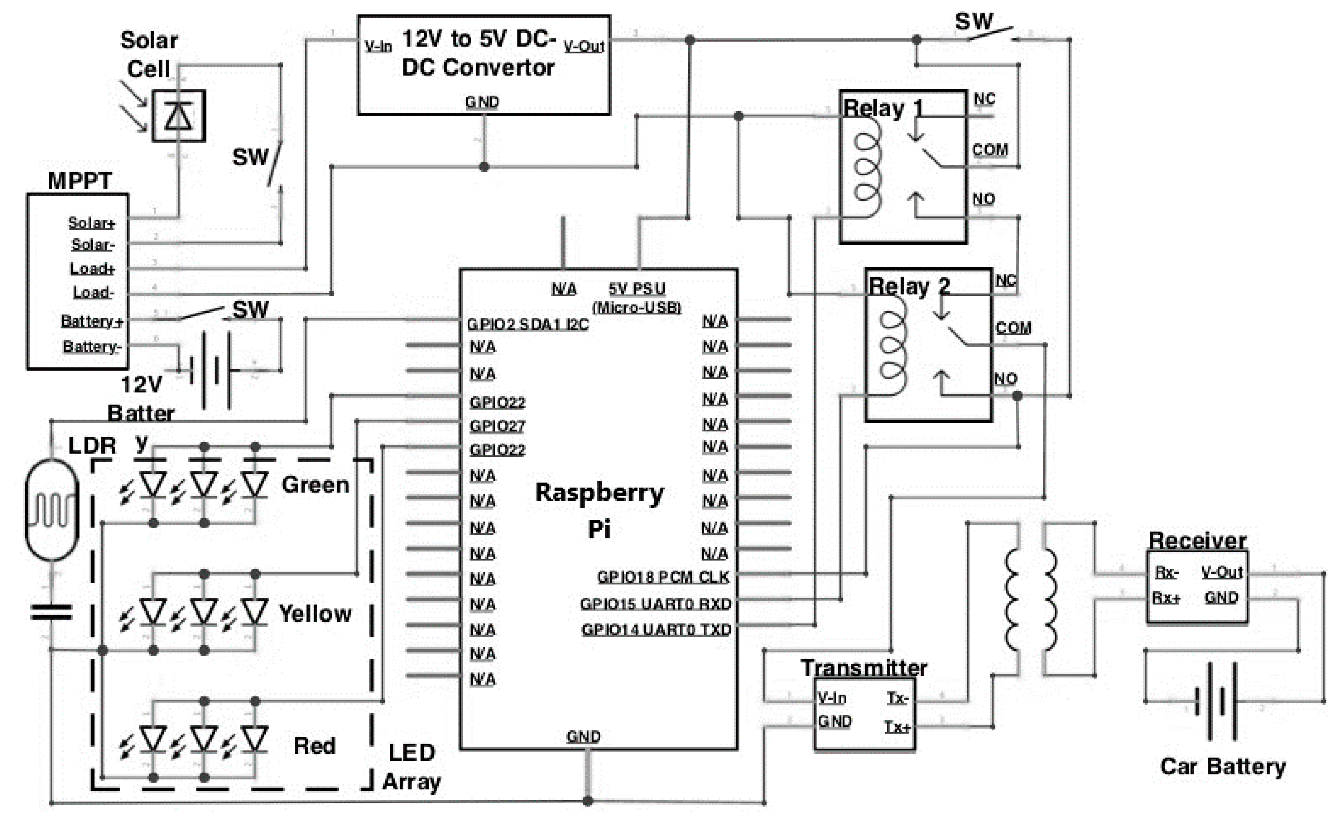
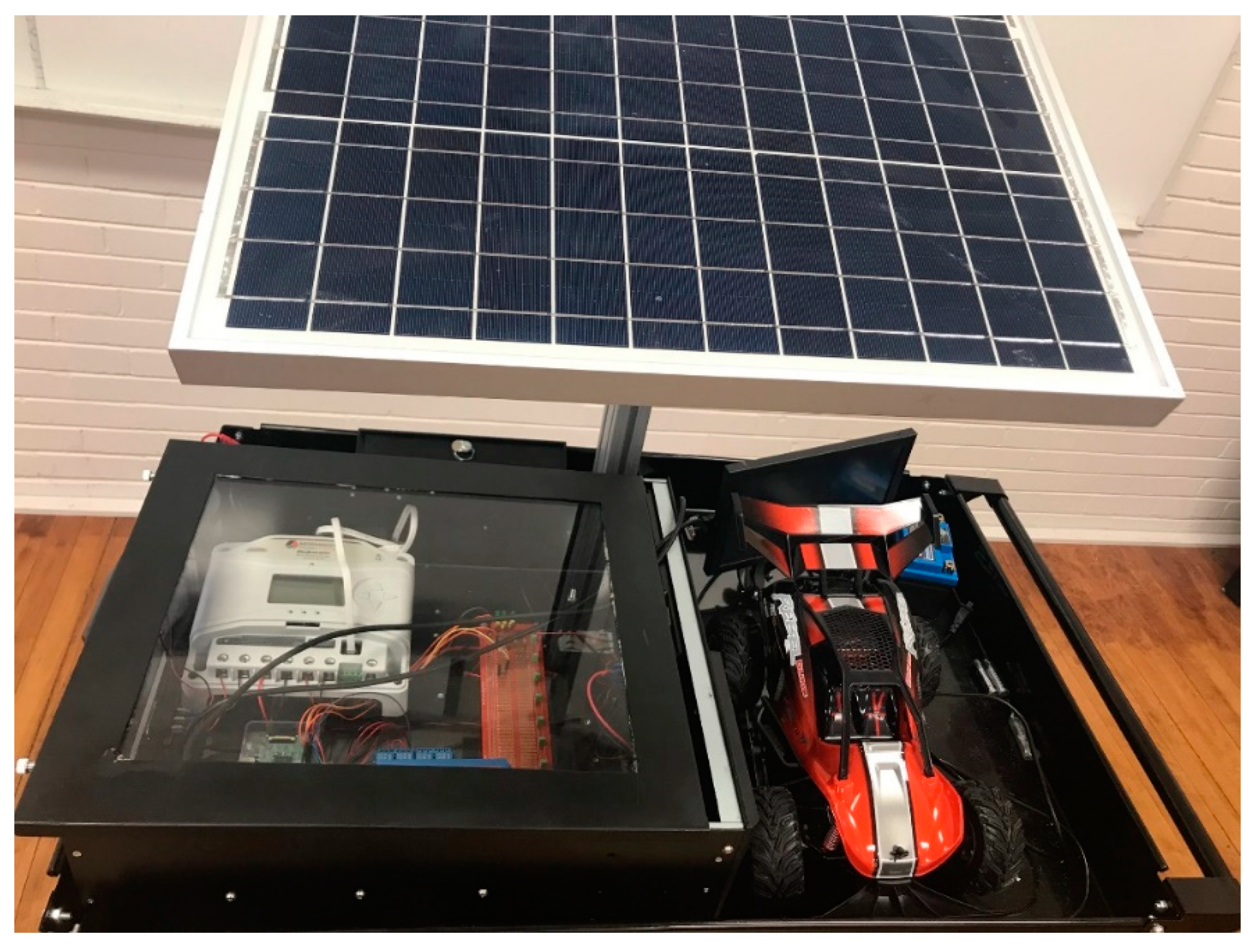
The MPPT charge controller is connected to the load to power various components. The load consists of a 12 V to 5 V DC-DC convertor, a Raspberry Pi microcontroller, a four-relay module, a series of nine LEDs (a 3 × 3 grid with each row controlled individually), a light dependent resistive (LDR) circuit, and a wireless transmitter/receiver to charge an electric toy car to represent electric vehicles for proof of the concept. The system also includes other smaller components, such as physical switches and terminals to support the desired functionality. Schematics and a picture of the solar microgrid are shown in
Figure 3 and
Figure 4, respectively. A list of hardware and costs are detailed in
Table 1.
3. Data Acquisition and Data Process
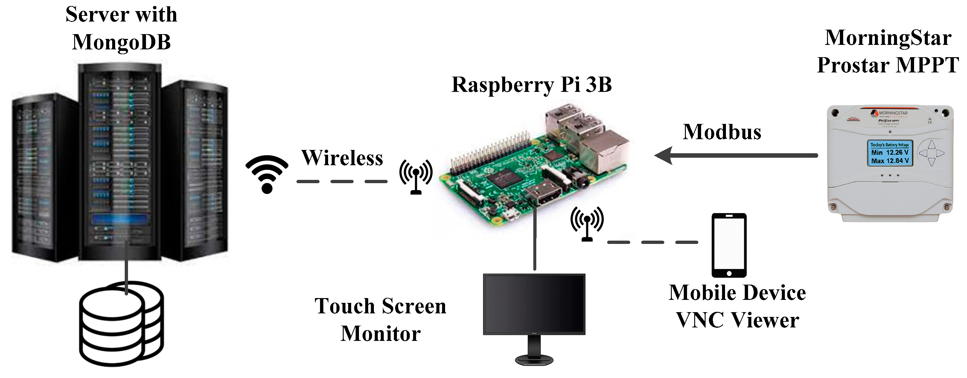
Data communication among the MPPT charge controller (Morningstar), Raspberry Pi 3 Model B, cloud server with MongoDB database, and graphical user interface is shown in
Figure 5. The MPPT charge controller is the central data sampling device that generates the electrical data about the system components including the solar panel, battery, and the loads. The sampled data were retrieved by the Raspberry Pi microcontroller and Modbus communications via a USB Meterbus adapter. Then the data were filtered and formatted to proper values on the Raspberry Pi and sent via WiFi to the cloud MongoDB. The Raspberry Pi was also connected to a touchscreen LCD monitor that provides a graphical user interface (GUI) to energize or de-energize the loads. Control to the loads on a mobile device from remote locations was realized through a Virtual Network Computing (VNC) Viewer connected to the Raspberry Pi.
Modbus is a communication method in which a device loads registers with data. These data can then be retrieved by another device as the client/server. For the microgrid system, the MPPT charge controller hosts the Modbus addresses where the data were retrieved. The data being monitored are the solar panel voltage and current, battery voltage and current, load voltage and current, maximum array voltage (daily), charger output power, charge state, load state, minimum and maximum battery voltage (daily), time in absorption, equalization and float (daily), heatsink temperature, battery temperature, and ambient temperature. The data provide detailed information on the operation of the solar microgrid.
4. Programming Logic and Graphical User Interface (GUI) Design
Two interconnected programs were designed and developed: main logic and GUI. The main logic program processes all data logics. The GUI program receives user inputs and send instructions to the main logic. Users can energize or de-energize the loads including the wireless car charger and the LEDs through the GUI, as well as on a mobile device remotely through VNC Viewer for the Raspberry Pi. VNC Viewer is a graphical desktop sharing system that allows the system to work as a remote laboratory, where hardware can be controlled remotely. All programming was done on the Raspberry Pi with Python programming language before the data were sent to the cloud database.
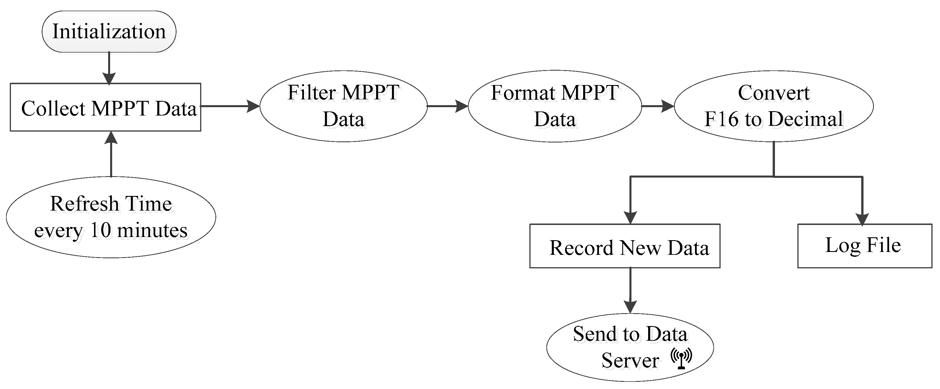
The flowchart of the main logic program is shown in
Figure 6. After initialization of the system environment, such as network IP addresses, port numbers, and other global variables, a data process loop with refreshing interval of 10 min is set by default. The refreshing interval is configurable. The first step in the loop is to collect MPPT data and keep the data in an array. Then the data are filtered, formatted, and converted from float 16 to decimal numbers. Finally, the data are packaged to JavaScript Object Notation (JSON) and sent wirelessly to the cloud MongoDB data server so that the data can be used for research, analysis, and visualization.
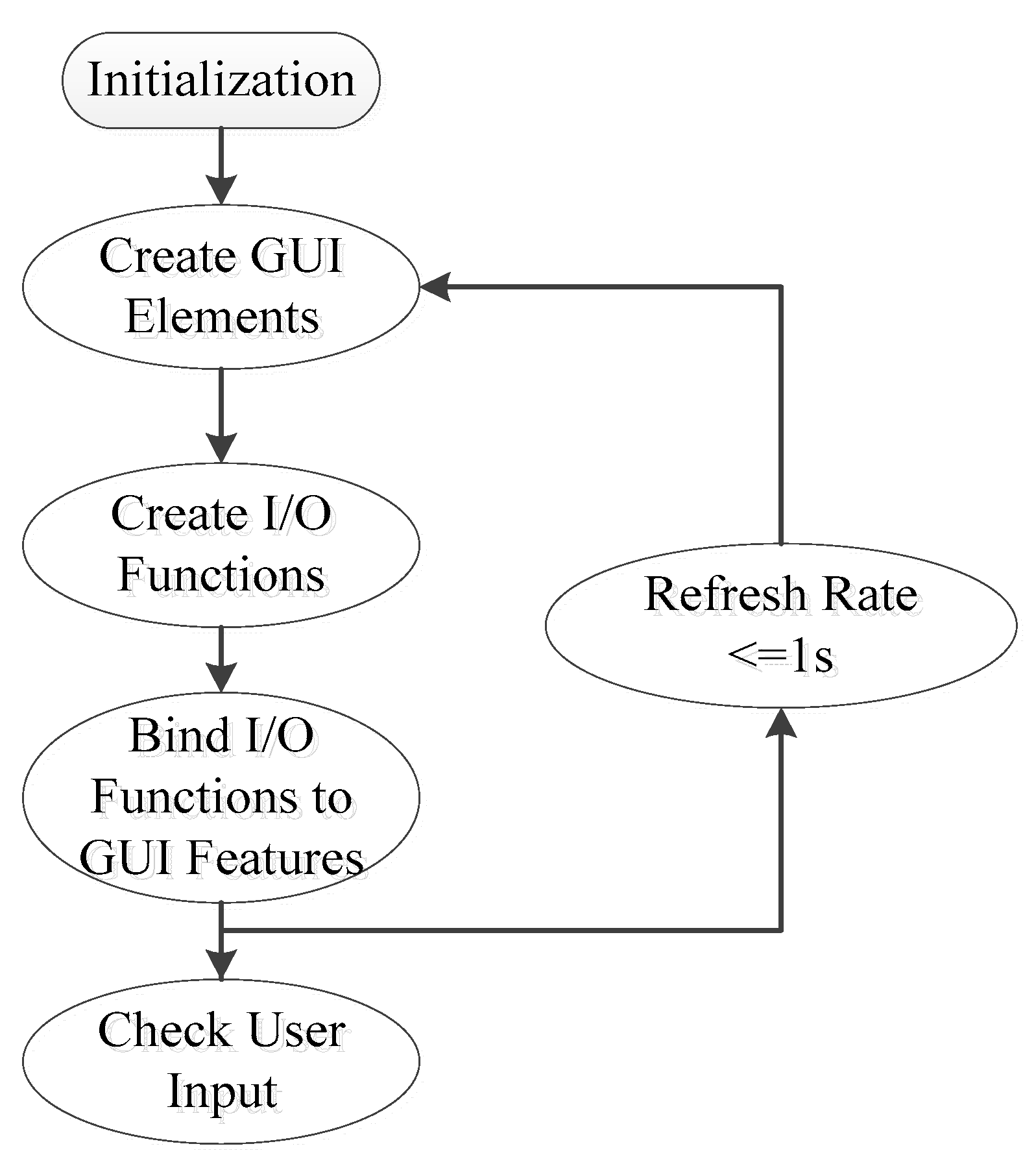
The flowchart of the GUI program is shown in
Figure 7. After initialization of the GUI program, once the main user interface is loaded and displayed, the GUI program refreshes and changes every second based on user inputs and environment adjustment.
5. Pedagogical Approach
The solar microgrid CPS has been used as a teaching tool for college students to increase their interest and knowledge of renewable energy. The system benefits undergraduate education and outreach program in many ways. First, it is exciting for college and pre-college students to observe and experiment with the system. The system has inspired their interest in and curiosity about alternative energy. Second, the solar microgrid CPS involves many topics in electrical engineering and mechanical engineering.
Problem-based learning (PBL) approach is an active, student-centered, and problem-centered method [
3,
30,
31]. It cultivates students’ independent and critical thinking. One drawback when knowledge is transferred mostly by lecturing is that students are not motivated to acquire knowledge independently. By using PBL approach, students’ interest and curiosity are stimulated, generating excitement and increasing interaction.
The system creates a central planform to integrate lectures, demonstrations, and experiments. Students can make changes to the system parameters and programming logic and observe the effect immediately. They become independent inquirers and learn there are different ideas and solutions for real world engineering problems. The following experiments were developed around the solar microgrid CPS: (1) data acquisition for renewable energy, (2) Python programming for Raspberry Pi, (3) data sampling, digitization, and process, (4) battery charging, (5) maximum power point tracking, (6) digital data communication, (7) user interface design and control logic, (8) database operations, (9) data analysis and report. Each experiment is stand-alone, while they are all related to the system.
Table 2 shows the learning objectives of each experiment. Students could understand the design and implementation of the entire solar microgrid system after completing the experiments.
The system was designed to be open and easy to modify. The undergraduate students were able to extend their theoretical knowledge and apply it in practical applications. The system also served as a testbed for senior design projects. Students could design and modify the existing system to expand its functions. Students’ ideas could be easily verified through the platform.
6. Experimental Results
The solar microgrid CPS was tested outdoors on a sunny day. The rechargeable battery was almost depleted of charge at the beginning of the test. The loads of LED lights and wireless car charger were energized. Data were collected automatically every 10 min.
Table 3 shows the voltage and current for the solar panel, the battery, and the loads, charger output power, and battery temperature. The MPPT charge controller provided the loads with the power from the solar panel and used additional power to charge the rechargeable battery.
The voltage for the photovoltaic (PV) and loads remained relatively constant over time. PV current was highest initially to charge the battery. As the state of charge of the battery increased, the MPPT charge controller reduced the output current from the PV to avoid overcharging the battery. From 10:50 am to noon, there was a large current flowing into the battery. After that, the battery current was rapidly reduced and went to almost zero at 13:00. At 13:20, 13:30, and 13:50, the battery current became negative, which means the battery was being discharged to provide power to the loads. Overall, since the solar irradiation was very good on the day of testing, the solar panel was able to provide sufficient power to the loads and charge the rechargeable battery. When the battery was fully charged after noon, solar power was curtailed by the MPPT charge controller.
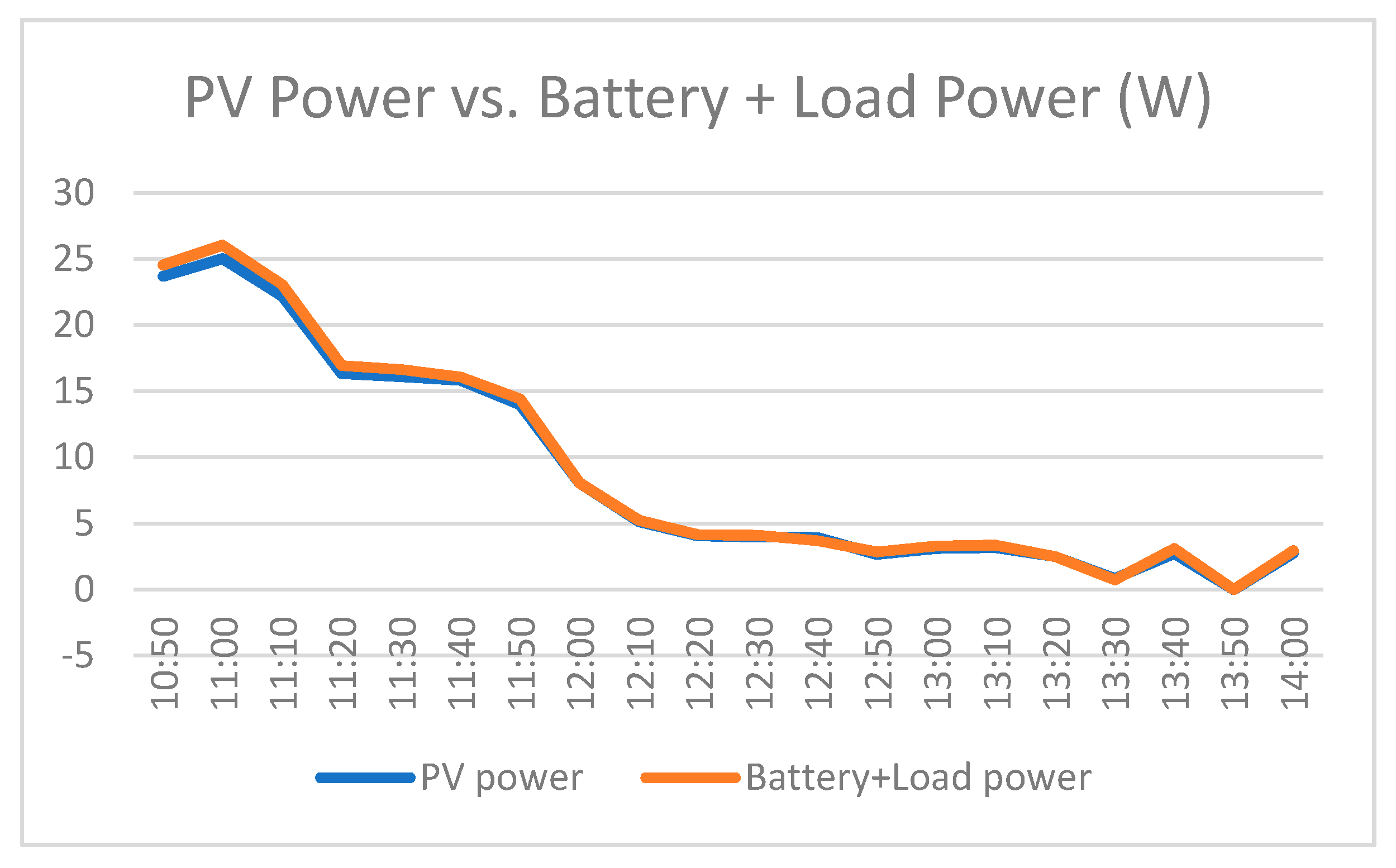
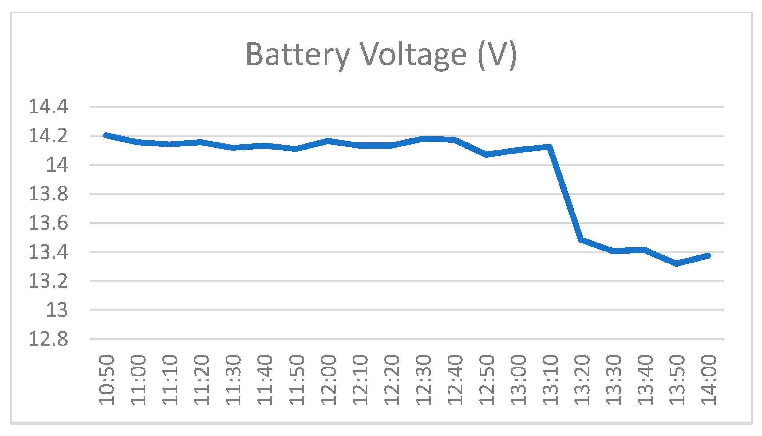
The PV provided a primary power source, and the battery supplied complementary source. The battery improved the microgrid’s stability and reduced effects of the intermittent nature of solar power. The changes of the PV output power vs. the sum of battery and load power are shown in
Figure 8. The battery voltage is shown in
Figure 9. It can be observed that after the battery was fully charged after 13:00, the charge controller reduced the battery voltage to the float voltage setpoint, where a very low rate of maintenance charge was provided.
In addition to the data in
Table 3, the MPPT charge controller was also able to retrieve the following values: heatsink temperature, ambient temperature, charge state, load state, PV voltage at maximum power, PV maximum output power, PV open circuit voltage, maximum battery voltage (daily), minimum battery voltage (daily), time in absorption (daily), time in equalization (daily), and time in float (daily). The data enabled remote system monitoring and provided faculty and students information on how the system operated.
7. Educational Assessment
The system was used as an enabling teaching tool for the engineering technology curriculum in junior/senior level courses. The demonstrations and experiments were used in TECH 375 Control Systems, TECH 476 Industrial Control Electronics and TECH 426 Electric System Applications for Alternative Energy. Students completed an anonymous questionnaire after participating in the demonstration and experiments. The questionnaire addressed two research questions:
- (1)
Did the demonstration and experiments enhance college students’ awareness and knowledge of renewable energy?
- (2)
Did college students perceive changes in their interest in renewable energy because of the demonstration and experiments?
The results in
Table 4 were processed using 1 for Not at all, 2 for A little, 3 for Somewhat, and 4 for Very much to calculate the means and standard deviations. They show the solar microgrid CPS demonstration and experiments greatly enhanced students’ perception of learning as compared with traditional instruction, and a majority of students perceived changes in their interest, awareness, and knowledge of renewable energy.
Students also completed a pre- and post- knowledge test containing 10 questions. The test was given in the first and last week of the semester. The group size for analysis was based on the number of students who completed both the pretest and posttest. Mixed analysis of variance (ANOVA) was used to analyze the tests. ANOVA is a collection of statistical models and their associated estimation procedures used to analyze the differences among means. The pretest had a score of (3.24 ± 1.147), and the posttest had a score of (7.65 ± 1.843). The mixed ANOVA comparing pretest to posttest scores revealed a significant increase in knowledge test scores from the beginning to end of the courses [F(1, 35) = 73.220, p < 0.001].
8. Discussion and Conclusions
This paper presented a teaching tool developed from a smart solar microgrid CPS. The system integrated the physical layer with the cyber layer that includes sensors, communication, and control. Demonstrations and hands-on experiments were developed around the platform. The experiments are stand-alone and can be conducted within a laboratory time frame. The hands-on experiments allowed students to connect classroom content with real world applications.
The system was used to teach engineering technology students solar power, control, data acquisition and process. We created a central planform to integrate lectures, demonstrations, and experiments for problem-based learning. Two research questions were asked during the assessment: (1) Did the demonstration and experiments enhance college students’ awareness and knowledge of renewable energy? (2) Did college students perceive changes in their interest in renewable energy because of the demonstration and experiments? The assessment results supported the expectation that the use of the solar microgrid along with innovative teaching materials in the laboratory would enhance students’ perceptions of learning as compared with traditional instruction and would increase their interest level and knowledge of renewable energy and STEM fields. In addition, the solar microgrid CPS described in this study can be easily scaled to higher power levels. The proposed system can be used to provide DC power to rural and developing areas where power is unavailable or unreliable. Future work can connect two or more solar microgrids and use an upper-level controller for hierarchical control. The primary control integrates control loops to regulate voltage, current, and power and defines the dynamic performance. The upper-level controller can provide advanced functions, such as power quality control, current sharing, and optimized operation. Future efforts can improve the intelligence of the system to achieve coordination among microgrids.
Author Contributions
Conceptualization, L.G.; methodology, L.G. and J.K.J.; software, J.K.J.; validation, L.G. and J.K.J.; formal analysis, L.G.; investigation, L.G.; resources, L.G.; writing—original draft preparation, L.G.; writing—review and editing, L.G.; visualization, L.G.; supervision, L.G.; project administration, L.G.; funding acquisition, L.G. All authors have read and agreed to the published version of the manuscript.
Funding
Partial support for this work was provided by the United States National Science Foundation’s Improving Undergraduate Science, Technology, Engineering and Mathematics Education (IUSE) program under Award No. 1712146. Any opinions, findings, and conclusions or recommendations expressed in this material are those of the authors and do not necessarily reflect the views of the National Science Foundation.
Data Availability Statement
The data presented in the study are available in this article.
Conflicts of Interest
The authors declare no conflict of interest.
References
- Yi, Z.; Dong, W.; Etemadi, A.H. A Unified Control and Power Management Scheme for PV-Battery-Based Hybrid Microgrids for both Grid-Connected and Islanded Modes. IEEE Trans. Smart Grid 2018, 9, 5975–5985. [Google Scholar] [CrossRef]
- Ameli, A.; Ameli, M.T. Smart Charging Management System of Plugged-in EVS Based on User Driving Patterns in Micro-GR. Int. J. Eng. Res. Innov. 2018, 10, 12–17. [Google Scholar]
- Muoka, P.I.; Haque, M.E.; Gargoom, A.; Negnetvitsky, M. DSP-Based Hands-On Laboratory Experiments for Photovoltaic Power Systems. IEEE Trans. Educ. 2015, 58, 39–47. [Google Scholar] [CrossRef]
- Beszedes, B.; Szell, K.; Gyorok, G. Redundant Photo-Voltaic Power Cell in a Highly Relable System. Electronics 2021, 10, 1253. [Google Scholar] [CrossRef]
- Mahmood, H.; Michaelson, D.; Jiang, J. A Power Management Strategy for PV/Battery Hybrid Systems in Islanded Microgrids. IEEE J. Emerg. Sel. Top. Power Electron. 2014, 2, 870–882. [Google Scholar] [CrossRef]
- Golsorkhi, M.S.; Shafiee, Q.; Lu, D.D.C.; Guerrero, J.M. A Distributed Control Framework for Integrated Photovoltaic-Battery-Based Islanded Microgrids. IEEE Trans. Smart Grid 2017, 8, 2837–2848. [Google Scholar] [CrossRef]
- Philip, J.; Jain, C.; Kant, K.; Singh, B.; Mishra, S.; Chandra, A.; Al-Haddad, K. Control and Implementation of a Standalone Solar Photovoltaic Hybrid System. IEEE Trans. Ind. Appl. 2016, 52, 3472–3479. [Google Scholar] [CrossRef]
- Lauria, D.; Lamb, S.; Abu-Aisheh, A. Designing Standalone Microgrid and Grid-Connected SmartGrid Hybrid Solar/Wind Energy Systems. Int. J. Eng. Res. Innov. 2016, 8, 83–93. [Google Scholar]
- Meng, L.; Shafiee, Q.; Trecate, G.F.; Karimi, H.; Fulwani, D.; Lu, X.; Guerrero, J.M. Review on Control of DC Microgrids and Multiple Microgrid Clusters. IEEE J. Emerg. Sel. Top. Power Electron. 2017, 5, 928–948. [Google Scholar] [CrossRef] [Green Version]
- Xuan, Y.; Yang, X.; Chen, W.; Liu, T.; Hao, X. A Novel Three-Level CLLC Resonant DC-DC Converter for Bidirectional EV Charger in DC Microgrids. IEEE Trans. Ind. Electron. 2021, 68, 2334–2344. [Google Scholar] [CrossRef]
- Masrur, M.A.; Skowronska, A.G.; Hancock, J.; Kolhoff, S.W.; McGrew, D.Z.; Vandiver, J.C.; Gatherer, J. Military-Based Vehicle-to-Grid and Architecture and Implementation. IEEE Trans. Transp. Electrif. 2018, 4, 157–171. [Google Scholar] [CrossRef]
- Dicorato, M.; Forte, G.; Trovato, M.; Munoz, C.B.; Coppola, G. An Integrated DC Microgrid Solution for Electric Vehicle Fleet Management. IEEE Trans. Ind. Appl. 2019, 55, 7347–7355. [Google Scholar] [CrossRef]
- Yu, Y.; Nduka, O.S.; Pal, B.C. Smart Control of an Electric Vehicle for Ancillary Service in DC Microgrid. IEEE Access 2020, 8, 197222–197235. [Google Scholar] [CrossRef]
- Bento, F.; Cardoso, A.J.M. Novel Fault Tolerant DC-DC Converter Architecture for LED Lighting Systems Operating in DC Microgrids. In Proceedings of the 2019 IEEE Third International Conference on DC Microgrids (ICDCM), Matsue, Japan, 20–23 May 2019. [Google Scholar] [CrossRef]
- Rodriguez-Diaz, E.; Vasquez, J.C.; Guerrero, J.M. Intelligent DC Homes in Future Sustainable Energy Systems: When efficiency and intelligence work together. IEEE Consum. Electron. Mag. 2016, 5, 74–80. [Google Scholar] [CrossRef] [Green Version]
- Dragicevic, T.; Lu, X.; Vasquez, J.C.; Guerrero, J.M. DC Microgrids-Part I: A Review of Control Strategies and Stabilization Techniques. IEEE Trans. Power Electron. 2016, 31, 4876–4891. [Google Scholar] [CrossRef] [Green Version]
- Emara, D.; Ezzat, M.; Abdelaziz, A.Y.; Mahmoud, K.; Lehtonen, M.; Darwish, M.M. Novel Control Strategy for Enhancing Microgrid Operation Connected to Photovoltaic Generation and Energy Storage Systems. Electronics 2021, 10, 1261. [Google Scholar] [CrossRef]
- Shahid, M.U.; Khan, M.M.; Hashmi, K.; Habib, S.; Jiang, H.; Tang, H. A Control Methodology for Load Sharing System Restoration in Islanded DC Micro Grid with Faulty Communication Links. Electronics 2018, 7, 90. [Google Scholar] [CrossRef] [Green Version]
- Azab, M.; Serrano-Fontova, A. Optimal tuning of fractional order controllers for dual active bridge-based DC microgrid including voltage stability assessment. Electronics 2021, 10, 1109. [Google Scholar] [CrossRef]
- Xiong, X.; Yang, Y. A photovoltaic-based DC microgrid system: Analysis, design and experimental results. Electronics 2020, 9, 941. [Google Scholar] [CrossRef]
- Lin, B.R. Soft switching DC converter for medium voltage applications. Electronics 2018, 7, 449. [Google Scholar] [CrossRef] [Green Version]
- Zhang, C.; Li, P.; Guo, Y. Bidirectional DC/DC and SOC drooping control for DC microgrid application. Electronics 2020, 9, 225. [Google Scholar] [CrossRef] [Green Version]
- Lv, J.; Wang, X.; Wang, G.; Song, Y. Research on control strategy of isolated dc microgrid based on soc of energy storage system. Electronics 2021, 10, 834. [Google Scholar] [CrossRef]
- Frivaldsky, M.; Morgos, J.; Prazenica, M.; Takacs, K. System Level Simulation of Microgrid Power Electronic Systems. Electronics 2021, 10, 644. [Google Scholar] [CrossRef]
- Mazumder, S.K.; Kulkarni, A.; Sahoo, S.; Blaabjerg, F.; Mantooth, A.; Balda, J.; de la Fuente, E.P. A Review of Current Research Trends in Power-Electronic Innovations in Cyber-Physical Systems. IEEE J. Emerg. Sel. Top. Power Electron. 2021, 6777, 1–17. [Google Scholar] [CrossRef]
- Bacha, S.; Picault, D.; Burger, B.; Etxeberria-Otadui, I.; Martins, J. Photovoltaics in Microgrids: An Overview of Grid Integration and Energy Management Aspects. IEEE Ind. Electron. Mag. 2015, 9, 33–46. [Google Scholar] [CrossRef]
- Akpolat, A.N.; Yang, Y.; Blaabjerg, F.; Dursun, E.; Kuzucuoglu, A.E. Design Implementation and Operation of an Education Laboratory-Scale Microgrid. IEEE Access 2021, 9, 57949–57966. [Google Scholar] [CrossRef]
- Patrascu, C.; Muntean, N.; Cornea, O.; Hedes, A. Microgrid Laboratory for Educational and Research Purposes. In Proceedings of the 2016 IEEE 16th International Conference on Environment and Electrical Engineering (EEEIC), Florence, Italy, 7–10 June 2016. [Google Scholar] [CrossRef]
- ProStar MPPT Solar Charging System Controller Installation, Operation and Maintenance Manual. Available online: https://www.morningstarcorp.com/wp-content/uploads/operation-manual-prostar-mppt-en.pdf (accessed on 1 May 2021).
- Jahan, K.; Bodnar, C.; Farrell, S.; Tang, Y.; Noshadi, I.; Slater, C.S.; Miller, D.S. Improving Students’ Learning Behaviors through Hands-on Algae Based Project—Rowan University. Int. J. Eng. Educ. 2019. Available online: https://www.researchwithrowan.com/en/publications/improving-students-learning-behaviors-through-hands-on-algae-base (accessed on 28 May 2021).
- Hu, Q.; Li, F.; Chen, C.F. A Smart Home Test Bed for Undergraduate Education to Bridge the Curriculum Gap from Traditional Power Systems to Modernized Smart Grids. IEEE Trans. Educ. 2015, 58, 32–38. [Google Scholar] [CrossRef]
| Publisher’s Note: MDPI stays neutral with regard to jurisdictional claims in published maps and institutional affiliations. |
© 2021 by the authors. Licensee MDPI, Basel, Switzerland. This article is an open access article distributed under the terms and conditions of the Creative Commons Attribution (CC BY) license (https://creativecommons.org/licenses/by/4.0/).


