Article

An Efficient Far-Field Wireless Power Transfer via Field Intensity Shaping Techniques

by
Martina T. Bevacqua
1,2,*,
Gennaro G. Bellizzi
3 and
Massimo Merenda
1,2,4,*
1
Department of Information Engineering, Infrastructures and Sustanaible Energy, Mediterranea University, 89124 Reggio Calabria, Italy
2
National Interuniversity Consortium for Telecommunications, Viale G.P. Usberti, 181 A Pal. 3, 43124 Parma, Italy
3
Department of Radiation Oncology, Erasmus University Medical Center Rotterdam, 3015 GD Rotterdam, The Netherlands
4
HWA srl—Spinoff UNIRC, 89125 Reggio Calabria, Italy
*
Authors to whom correspondence should be addressed.
Electronics 2021, 10(14), 1609; https://doi.org/10.3390/electronics10141609
Submission received: 8 June 2021 / Revised: 28 June 2021 / Accepted: 30 June 2021 / Published: 6 July 2021
(This article belongs to the Special Issue Antenna Array Processing for Wireless Power Transfer)

Abstract

:
Radiative (or far-field) energy replenishment for devices such as smartphones, laptops, robots, and small electric appliances paves the way to autonomous and continuous devices functioning, thus bypassing the need of operation interruptions, human maintenance activities, and replenishment by wired transformers. In this work, we investigate the feasibility of using a properly engineered antenna array able to deliver radiative power to devices in need of energy replenishment during their normal and unsupervised activity, whose locations are unknown. Both the case of single and multiple devices needing energy replenishment are addressed. A quantitative proof-of-concept study is carried out to validate the proposed approach. A 3D scenario is simulated to study the case of devices in need of energy replenishment within a standard office environment. Different antenna array configurations are investigated and the corresponding performances benchmarked against a standard installation of recharging antennas. Results confirm the outstanding capability of the proposed approach in terms of confinement and maximization of power transfer. Finally, in this framework, we also propose an efficient communication protocol that is able to manage multiple recharge demand given different operational rules.

1. Introduction

Early in the 20th century, the Serbian-American inventor Nikola Tesla was the first to envision the application of electromagnetic waves for wireless power transfer (WPT) using near-field inductive and capacitive coupling, as well as resonant inductive coupling [1]. The ideas of Tesla were later rearranged, and a new interest has emerged in energy-transfer mechanisms [2,3,4], now known as radiative or non-radiative.
Radiative energy transfer is considered in long-range applications, when the demanding devices are located usually in the far-field zone of the antenna radiating the electromagnetic waves. However, the energy transmission efficiency of systems is very low due to the omni-directional nature of the usually adopted antennas. Unidirectional antennas instead require an uninterrupted line of sight and sophisticated tracking mechanisms [5]. As such, the lack of efficiency of the radiative transfer reduces the application to only energy-harvesting applications, where a few tens of microwatts of power can be collected up to 10 m from the transmitter.
On the other hand, non-radiative energy transfer is based on near-field magnetic coupling of conductive loops and is commonly used for WPT in short-range and mid-range applications. The energy exchange of two resonant objects is more efficient (although omnidirectional) than the radiative transfer, with reduced interference and losses into surrounding objects. However, exploiting the coupling effects requires a reduced distance and the exact knowledge of the system geometry for an optimal tuning, depending also on the available area of the device [6].
Recently, a considerably increasing demand is arising for automation of the recharging of electrical and electronic devices that are commonly used in industrial, domestic, or office environments, including automated devices and robots for logistics management, laptops, smartphones, personal digital assistants (PDAs), etc. Mature wireless charging solutions have been proposed to satisfy this need. However, most of them are based on non-radiative energy transfer, thus affecting the operational time and the performance of the whole system in the case of moving devices and continuous operations.
To overcome these drawbacks, the optimal WPT solution would be based on radiative energy transfer, without the mandatory request of a line of sight between transmitter and receiver, and wherein a greater amount of energy is delivered and confined within the spatial location where it is required. In this respect, different approaches have been proposed in the literature [7,8,9,10,11,12,13]. For instance, a unified approach for energy harvesting and wireless power transmission is provided in [13], while experiments for radiative transmissions are provided in [11]. Furthermore, in [12], a technique for the synthesis of antenna arrays, accounting simultaneously for both near-field focusing and far-field specifications, has been proposed. However, the state-of-the-art approaches for field focusing often fail to address energy replenishment, require information on the location of the device to be recharged, as well as knowledge of the electromagnetic properties of the scenario at hand, thus limiting the application to the direct energizing of devices in the known scenario. Moreover, the state-of-the-art approaches for field focusing do not consider the case of multiple energy replenishment.
This work proposes a novel approach to overcome the above intrinsic limitations of radiative energy transfer in terms of the unidirectionality of the transmission in the line of sight of electromagnetic waves and the low power efficiency. To this end, the main contributions of this paper are:
  • the design of an antenna array to recharge portable devices and small home appliances;
  • the introduction of a communication protocol to manage plural energy demands.
The first item is pursued by means of a power confinement approach, built on top of an optimized field focusing and shaping technique [14], based on the well-known time reversal (TR) [15]. In particular, the optimized technique in [14] is tailored for the WPT application, wherein the location of the device is not a priori known, by taking into account the capability of the devices to wirelessly communicate with the array. While in [16] a preliminary analysis in a 2D scenario and single WPT is reported, in this paper we report a 3D quantitative study of the transferred power in case of both single and multiple WPT, and three different array configurations. In particular, a comparison to a standard installation of recharging antennas is performed, thus assessing the capability of the designed array to improve power efficiency. This analysis involves full-wave numerical simulations of a 3D scenario, mimicking an office environment with the presence of a human body, office furniture, and concrete walls.
Finally, in order to manage plural energy demands, a simple yet efficient communication protocol is also introduced which makes it possible to create a priority queue for efficiently locating and recharging only the devices with a battery level below a certain threshold.
The paper is organized as follows. In Section 2, the electronic scheme of the receiver circuit requiring the WPT is discussed. In Section 3 a brief description of the optimized shaping technique herein adopted to design the antenna array is reported. In Section 4, the numerical quantitative analysis is depicted, discussing the performance of the proposed approach and an example of application in a 3D scenario. Then, Section 5 reports the proposed communication protocol. Finally, conclusions are drawn in Section 6.

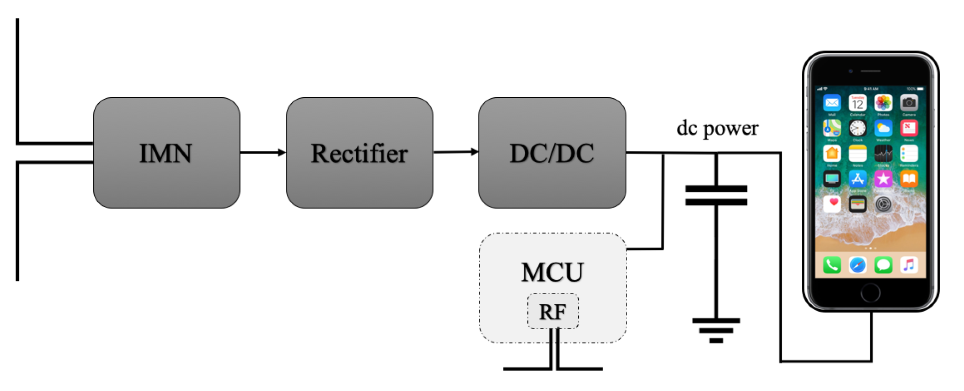
2. Receiver Electronic Circuit Design

Recharging wireless electrical and electronic devices is a time- and power-consuming task which implies (in the case of moving devices) human maintenance, partial out-of-servicing, and shortages of availability. In this work, we refer to commonly used devices in industrial or office environments such as small robots, laptops, smartphones, and PDAs. Usually, these device classes require a dc-connected charger for their replenishment, or a non-radiative coupled wireless charger.
The herein proposed idea of wirelessly delivering a usable recharge power within the device implies the exploitation of a radio frequency (RF)-to-dc conversion circuit. As the wireless delivery of dc power is unfeasible, we consider the confinement of the RF power on a device which includes a power-receiving part, locally exploiting an RF-to-dc conversion circuit. This makes it possible to extract a usable dc power from RF signals received by the antenna. The working principle is the same as that of a rectifier, but the design and tuning of the system must take into account (1) the variation of the input impedance caused by the variation of the input power, (2) the load instability, and (3) the environmental conditions [17]. In general, it is not possible for an RF energy harvester to perform well in all input power conditions, and a proper impedance-matching network is required [18]. A suitable alternative solution is to dynamically adapt the impedance to changing conditions, on-the-fly [19]. Nevertheless, the adaptive impedance matching strategy needs system-level management in response to variable conditions, implemented by a proper logic, actuating the algorithm for the maximization of the power transfer from the input (i.e., the rectenna) to the load. To ensure the maximum power-delivery efficiency, a fixed RF input power is desirable; however, it is not achievable because the RF power density, environmental conditions, scenario, and device position change and cannot be foreseen or compensated. In this work, in order to overcome this problem, the antenna array has to be designed in such a way to deliver an RF power density at the object above the switch-on threshold of the rectifier and to allow recharging with regards to the device class (e.g., greater than −10 dBm considering systems as described in [17,20]. Regarding the load current of the harvester, it can be fixed, thus eliminating a degree of freedom in the impedance-matching optimization, paving the way to a simple implementation of the RF harvester with almost fixed RF input power and output load.
The block scheme of the receiver is depicted in Figure 1, showing an impedance-matching network (IMN), a rectifier, and a dc/dc converter that supplies power to a smartphone—an example of a suitably rechargeable device that already includes several RF transmitters and computation capabilities for the management of the protocol that will be discussed in the further section. In more detail, the impedance-matching network is a required block to adapt the impedance of the receiving antenna to the impedance of the electronic circuit, whose value also varies with the input power values and the working load conditions. The rectifier is usually constituted of Schottky diodes that exhibit a very low voltage drop, allowing the maximization of the power converted. Dickson and Villard are very common topologies used to this end [17,18]. The output of the rectifier section is an unregulated dc power that can be used to power electronic circuits and systems directly or boosted by a dc/dc converter that provides regulated and fixed output voltage values.
An optional low-power microcontroller unit (MCU) with an integrated RF transmitter can be added to the system to provide sensing, computation, and bidirectional transmission features. As such, the device has a high-efficiency low-power technology (Lora, Bluetooth Smart, Zigbee, etc.) able to send periodic and omni-directional signals to the antenna array.

3. Array Design via Optimized Field Shaping Approach

A properly engineered antenna array is a way to improve energy delivery and power confinement within devices in need of WPT. To this end, the antenna array has to be designed to focus or shape the RF field intensity within the devices requiring the WPT. This is a twofold task. First, both the geometry and the number of elements of the antenna array need to be properly engineered to the case at hand, still considering the well-assessed theory [21,22]. Second, the field intensity shaping is tackled by determining the complex excitation coefficients (power and phase) feeding the antenna array. In the following, we deal with the second task and consider a phased antenna array of fixed geometry.
Shaping the field intensity represents a challenging problem of intrinsic theoretical interest that is also relevant in several applications [17,23,24,25,26,27,28,29,30], especially in the case of unknown (or partially unknown) scenarios [31,32]. The approach proposed in this work originates from the general-purpose approach in [14] and was tailored to this specific WPT application for device replenishment, wherein the location of the device is not a priori known. In the following, we refer both to single and multiple WPT requests.

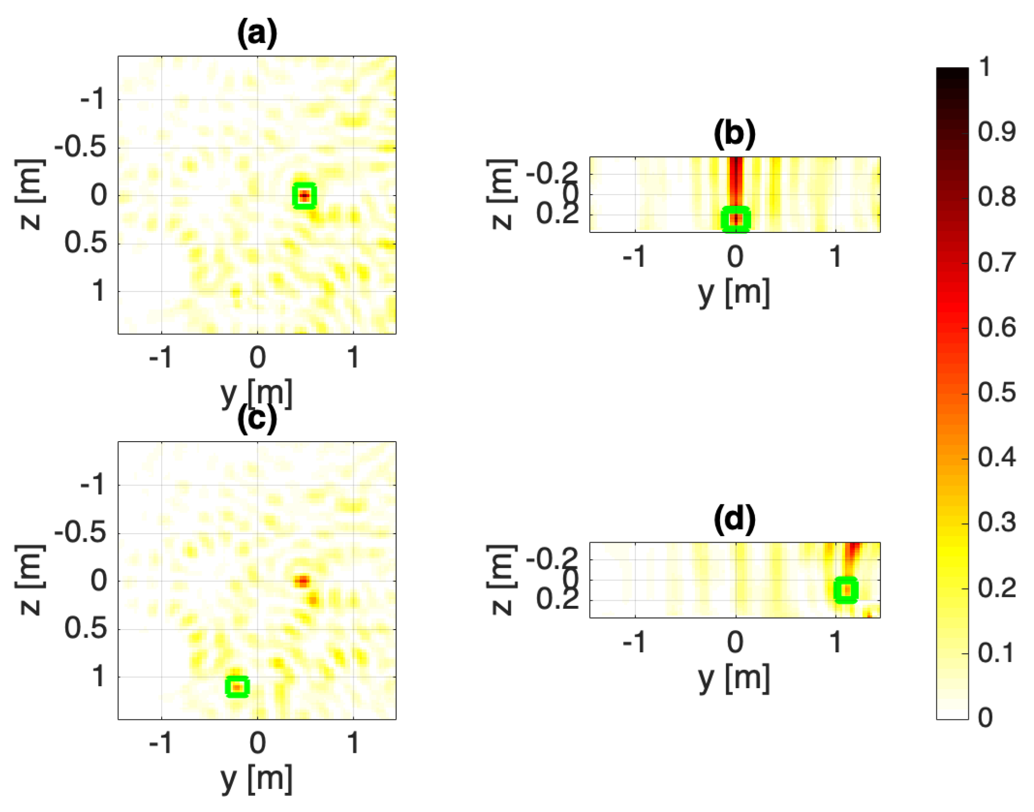
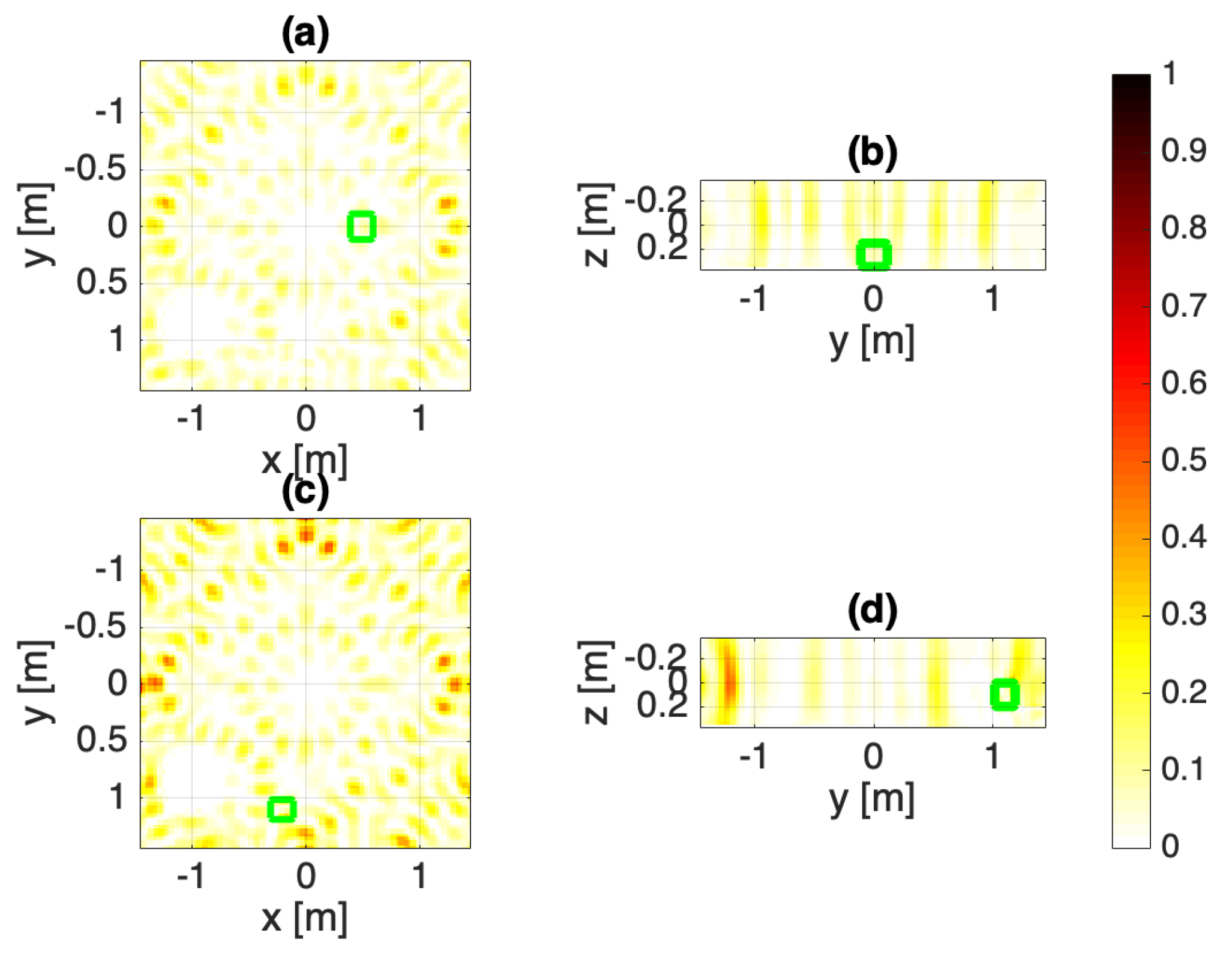
3.1. Case 1: Single WPT through TR Focusing

In the case of a single WPT request, the design approach adopted herein involves the well-known time reversal (TR) [15], which is a popular method to focus the RF field intensity in a given target point. It is a real-time and straightforward method, as it only requires the processing of the RF signal measured by the array antennas when an elementary source is located within the unknown object [33]. From a mathematical point of view, by denoting with r ̲ t the target point, and with Ψ n ( r ̲ t ) the total field measured by the n-th antenna of the array when a unit amplitude point source is located at the point r ̲ t , the complex excitations I n of the n-th antenna can be determined as:
I n ( r ̲ t ) = Ψ n ( r ̲ t ) * E n i n c ( r ̲ t ) l 2 2
where * denotes the complex conjugate, · l 2 is the l 2 —norm evaluated with respect to the antenna positions, and E n i n c is the field radiated in free space by the n-th antenna. According to the equation above, the complex excitation of each antenna composing the array can be evaluated as the complex conjugate of the field measured when a unit amplitude point source is in r ̲ t .
It is important to note that, in contrast to the standard TR theory [15], in this paper the complex excitations I n in Equation (1) are normalized with respect to the energy of the field radiated in free space by the n-th antenna in r ̲ t . This normalization plays a key role. Indeed, it makes it possible to take into account the fact that the energy of E n i n c varies within the investigation domain. Note that, for the application at hand, r ̲ t identifies the device’s position.

3.2. Case 2: Multiple WPT through O-mt-TR Shaping

In case of multiple targets requiring WPT, the approach adopted herein, known as optimized multi-target time reversal (O-mt-TR) [14], pursues the shaping of the field intensity by adding the contributions gathered by several focusing problems into the different target points r ̲ t i , identifying the position of the different devices. This approach consists of optimally determining the phase shifts ϕ of the fields focused via TR on each target point r ̲ t i , instead of adding them in-phase. From a mathematical point of view, by considering two devices and by denoting their positions with r ̲ t 1 and r ̲ t 2 , the complex excitations I n can be determined as:
I n = I n ( r ̲ t 1 ) + I n ( r ̲ t 2 ) e j ϕ
where I n ( r ̲ t 1 ) and I n ( r ̲ t 2 ) are determined as in the previous subsection, and ϕ is in the range [ 0 , 2 π ] . In its present implementation, the approach explores all the possible phase shift configurations and consequently picks the optimal one (according the specific application requirements), and selects the corresponding excitations by a-posteriori observing the achieved performance. For more details about the selection of ϕ , the interested readers are referred to [14,32]. Note that the following shaping approach can also be adopted in the case of arbitrary-shaped and extended space regions.
Both of the above described approaches (TR and O-mt-TR) have the interesting ability to create a private and direct energy transfer channel with the devices. However, they require the knowledge of Ψ n ( r t ̲ ) and, hence, of the electromagnetic properties of the investigation scenario. Unfortunately, for the application at hand, the scenario is unknown or partially unknown. In this paper, in order to avoid a preliminary sensing step [31,32] aiming at imaging and characterizing both the geometry and electromagnetic properties of the scenario under test, some advantages are taken by exploiting the device’s ability to communicate with the array, as described in Section 2. Accordingly, in the above equations, Ψ n ( r ̲ t ) represents the RF signal acquired by each antenna when the device is omnidirectionally transmitting. Moreover, the capability of TR to detect and retrieve the position of unknown objects [34,35,36] is also exploited, thus making it possible to estimate the device’s position r ̲ t .
It is important to note that the approaches proposed herein for WPT are real-time and able to deal with moving devices. As a consequence, the array can be reconfigured each time the device requiring WPT moves and sends a new RF signal to the array.

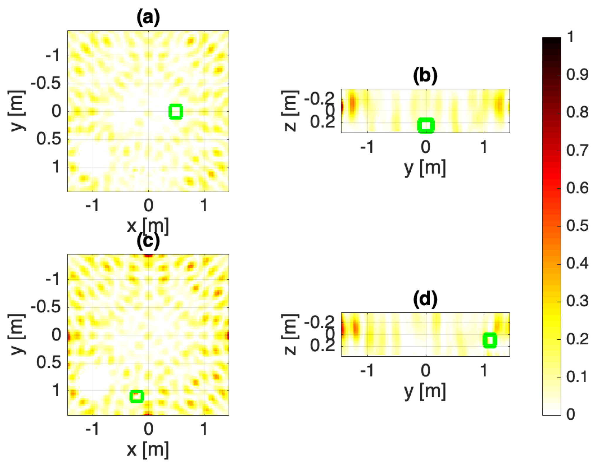
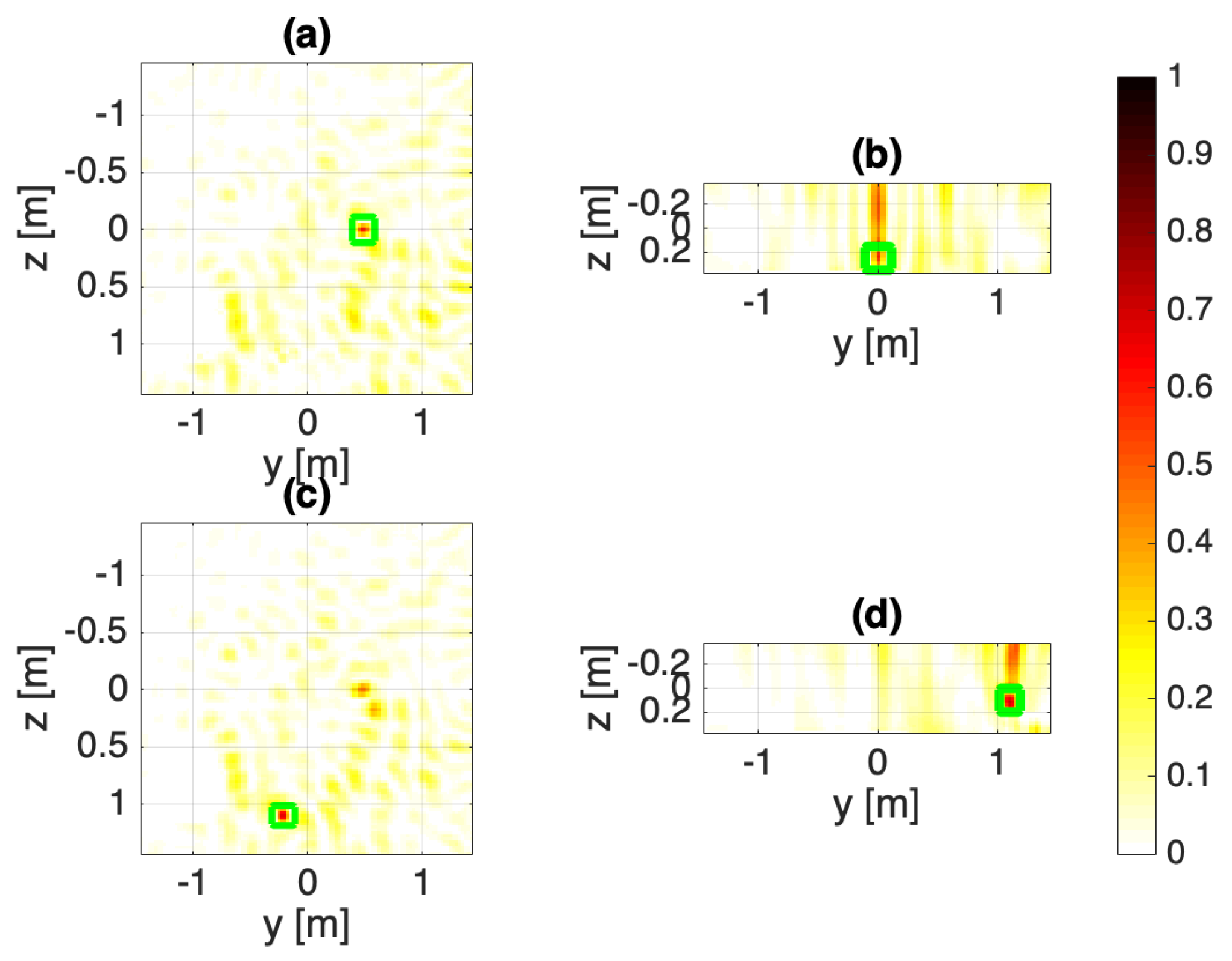
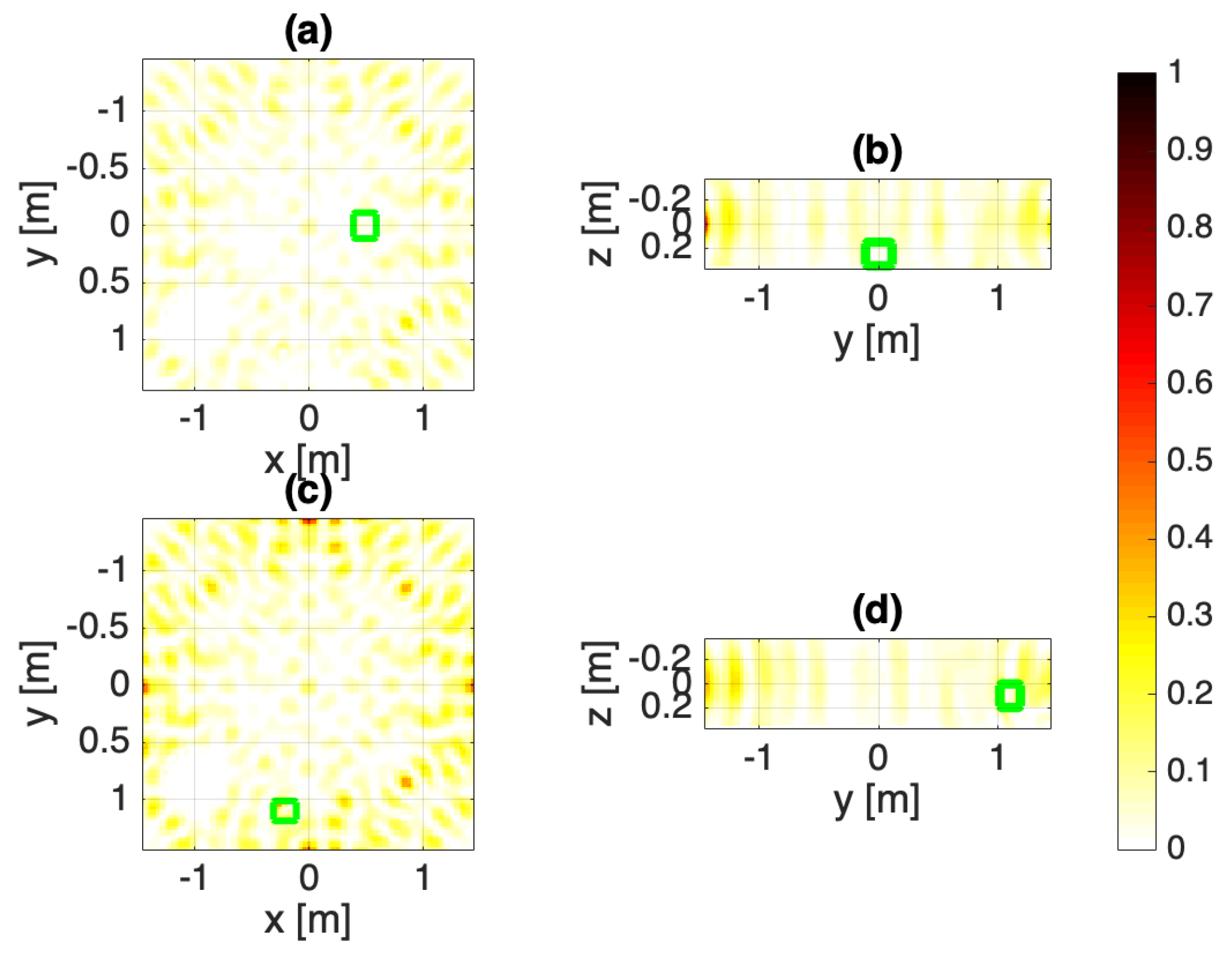
4. Numerical Assessment in a 3D Environment

The performance of the proposed WPT approach is tested over a realistic 3D indoor scenario mimicking an office environment (see Figure 2). Indeed, WPT can be relevant not only in industrial applications, but also for domotics in order to design smart homes and offices. The considered environment consists of a 3.4 × 3.4 × 2.2 m3 room filled with air ( ε = 1 and σ = 0 S/m, where ε and σ are the relative electrical permittivity and conductivity, respectively). The room is surrounded by concrete walls of 20 cm thickness with electrical properties ε = 4 and σ = 10 mS/m. Inside the room, some furniture with size 60 × 60 × 80 cm3 ( ε = 3 , σ = 1 mS/m) and 140 × 180 × 65 cm3 ( ε = 5 , σ = 10 mS/m) are also considered (see green and violet parallelepipeds in Figure 2). Moreover, a human body is considered inside the room, modeled as cylinder with radius 25 cm and height 1.7 m with electrical properties equal to the average between fat and muscle tissues ( ε = 40 , σ = 0.4 S/m)—see the yellow cylinder in Figure 2. Finally, two devices are modeled as two plastic cubes with side length 20 cm and electrical properties ε = 2.5 and σ = 10 mS/m (see the light blue and magenta squares in Figure 2).
The electromagnetic field distributions are computed for each antenna using Sim4Life (v.4.4.1.3808, Zurich MedTech, Zurich, Switzerland). An 868 MHz excitation harmonic signal is applied for 20 periods to each antenna. The size of the calculation domain is ≈30 million cells. Three different array configurations are considered. In all cases, the antennas composing the array are located on the walls, that is, the room’s inner perimeter. In particular, each antenna is a λ b / 2 dipole along the z-axis, where λ b is the wavelength in air. In the first two configurations, referred to as A and B, 20 antennas are considered, with 5 antennas on each wall. In configuration A, the antennas are alternatively distributed at two different heights z = 0.10 cm and z = 0.10 cm (see Figure 2), and the reference system is located at the center of the room. In configuration B the antennas are placed at the same height from the floor (i.e., z = 0 ). Finally, in the last configuration, C, 12 antennas are exploited, all arranged at z = 0 .
For each configuration, two different working conditions are considered. The first considers a single WPT. To this end, the array design is pursued by simply adopting the processing procedure in Section 3.1. The second working condition consists of simultaneous and multiple WPT. In this case, the complex excitations feeding the array are optimized by means of the O-mt-TR, described in Section 3.2. In order to understand the key role of an ad hoc array design, the results are compared to a standard installation of recharging antennas. A commercial example of this latter is represented by the TX91501B Powercaster Transmitter [37] that broadcasts radio waves for remotely powering IoT nodes. In the standard installation considered herein, each antenna is fed with unitary excitations, using the array configurations described above. Then, all possible interferences of the RF signals generated by the different antennas are not exploited. Moreover, no processing of the RF signal that the device transmits to the array is performed. The results are shown in Figure 3, Figure 4, Figure 5, Figure 6, Figure 7, Figure 8, Figure 9, Figure 10, Figure 11 and Figure 12, which depict the normalized squared amplitudes of the fields obtained through the different design procedures and array configurations. The scale is between 0 and 1, and the red parts correspond to larger values of the field amplitude, while the yellow and white parts correspond to smaller ones.
The performance is quantitatively assessed using a synthetic parameter, known as target coverage [14], defined as the l 2 —norm of the normalized squared field amplitudes within the targets—that is, E ^ l 2 O I , wherein E ^ is the electric field normalized with respect to their maximum in the region of interest. So, it is the integral of the squared amplitudes of the electric field within the targets. This synthetic parameter is proportional to the power transferred to the device. The higher the target coverage, the higher the transferred power. Table 1 reports E ^ l 2 O I for the different working conditions and array configurations.
Results show that TR and O-mt-TR are capable of improving the WPT at the device(s), while keeping it curbed elsewhere, as opposed to the case where no design procedure is adopted (array unitary fed). In particular, in this latter case, power confinement cannot be obtained and power is also transferred in undesired directions.
Among the array configurations, the arrangement wherein 20 antennas are alternatively shifted with respect to z = 0 (configuration A), makes it possible to better control the field intensity in x- and y-axes and, thus, the power transfer to the device. Moreover, in this case, the antennas’ spacing Δ is fixed according to the Nyquist–Shannon criteria [21]. On the other hand, in the 12-antenna array, the spacing is such that Δ λ b / 2 , thus limiting the desired WPT to the devices.
Note that when the number of antennas is reduced and their arrangement is unable to collect sufficient signal diversity along the z-axis, a tight control of the field along the z -axis is not possible. In order to overcome this drawback, more antennas have to be located at different heights.

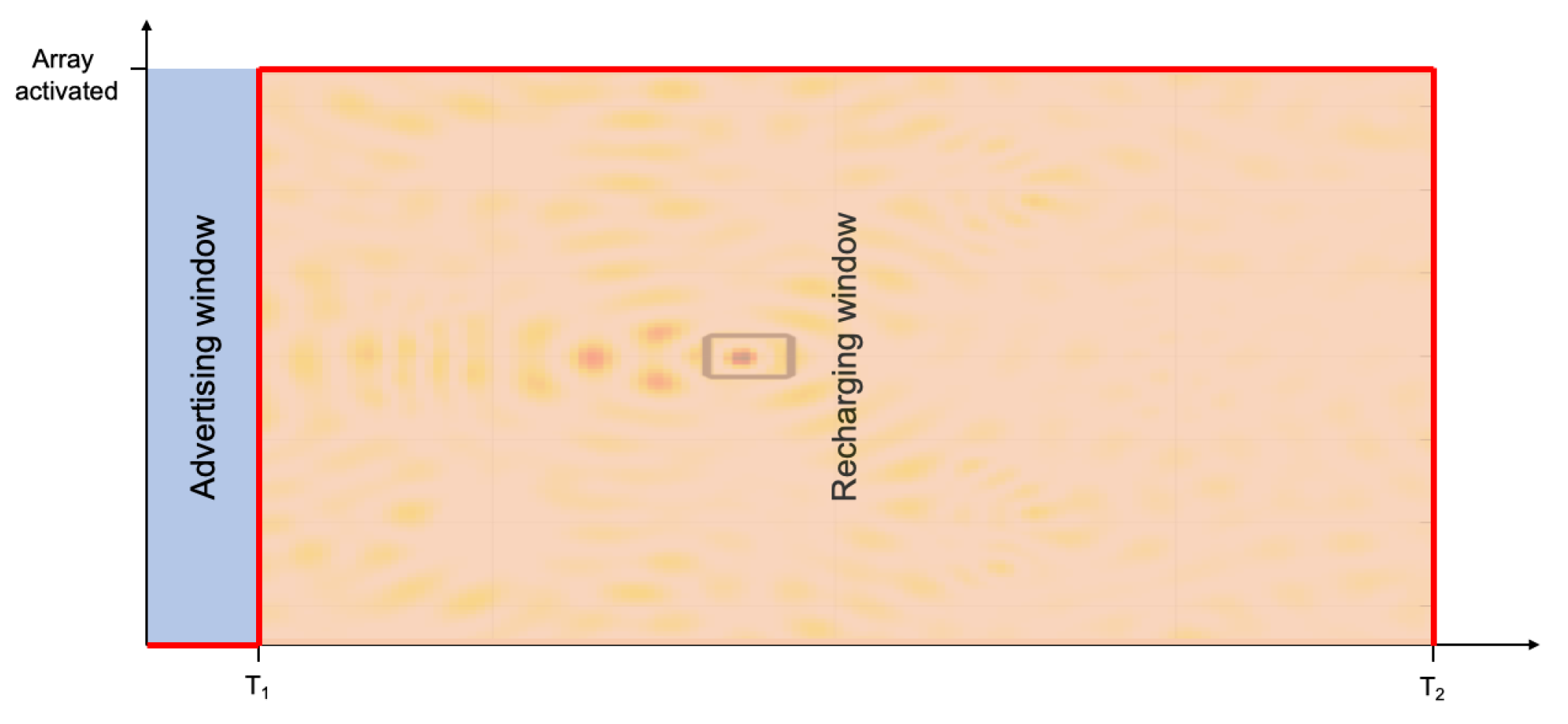
5. An Efficient Communication Protocol for WPT

In order to manage multiple WPT requests, a simple yet effective communication protocol is designed between a plurality of devices and the antenna array. Starting from a proper processing of the RF signal transmitted by the device, the protocol is able to provide augmented data, that is, localization, moving velocity, and charge rate request of the devices. Moreover, it defines a queue priority for the optimal time-efficient replenishment of multiple devices with minimum prior data while considering saving requirements for replenishing several items simultaneously.
The demand charge rate for each item is known a priori as an intrinsic characteristic of the device class, while the charge level is provided in real time in a proper communication window. The main goal is to reduce shortages and out-of-servicing due to the discharge of the devices, by considering negligible the computational burden related to the array design.
As depicted in Figure 12, in a fixed advertising window of time duration T 1 , by using a proper communication technology that depends on the available infrastructure (e.g., Bluetooth Low Energy, LoRA, or Wi-Fi), the devices transmit to the antenna arrays an RF signal, together with their device identification (ID) and charge levels. By using the device ID, containing information about the device class, the array detects the minimum requested field intensity for the replenishment task for every device. Then, by combining the requested field intensity with the remaining charge level, a proper ordered list of replenishment priority is created. The ordering strategy can be application specific (considering special priority) preferred replenishment hours, etc.
Subsequently, the first item in the list, namely, the device needing replenishment with maximum priority, is implicitly localized and the array is consequently designed by properly processing the RF signal as described in Section 3. Then, the power is delivered directly to the device for a time T 2 and until the next advertising window.
The duration of the advertising window T 1 depends on the used technology and the number of active devices, and can be tuned for optimal operation. The duration of the recharging window T 2 is a function of the charge amount to be transferred, as well as the number and velocity of devices. The ratio T 2 T 1 + T 2 defines the replenishment duty cycle. In the case of a moving target, the recharge can be ensured provided that the device sends a new RF signal in the new position. The device velocity can then be evaluated by measuring the position difference between the subsequent RF signal transmissions, with the a priori known time difference T 1 + T 2 .

6. Conclusions

In this work, an innovative procedure was introduced to improve the efficiency of WPT when a radiative energy transfer mechanism is exploited. The proposed procedure is based on the proper design of an antenna array that is able to confine and efficiently deliver RF energy at the devices requiring the WPT. The array design is pursued by tailoring an optimized field intensity shaping technique, recently introduced in the literature in the case of a known scenario [14]. As the scenario at hand was unknown (or partially unknown), the technique was adapted by taking into account the capability of the devices to communicate with the array and by properly processing the RF signal detected by the antenna array.
A numerical study in a 3D environment was pursued by considering different numbers of antennas and arrangements, as well as both single and multiple WPT. The results showed that a proper array design provided a maximum increase of the replenishment energy up to three times higher compared to when the array was fed with unitary currents. These exciting results also imply that the input power requested from the antenna array can be reduced with respect to a standard installation, for the same amount of transferred power. Moreover, the results demonstrate that the array design procedure can manage multiple WPT and maintain control of the amplitude of the field intensity in the room. In particular, array configuration A could ensure a better RF field confinement and a minimum increase of the replenishment energy on the target two times greater than the one obtained with the standard installation. On the other hand, the performance was limited in configuration C, as the number of antennas was not sufficient to ensure a proper control of the field intensity within the office room.
For the sake of multiple requests management, the paper also proposed an efficient communication protocol that is able to establish a priority list depending on the device charge level and to provide augmented data (e.g., moving velocity). The protocol time windows can be properly tuned to improve system efficiency and reduce latency in the WPT procedure.
Finally, the combined use of RF field intensity shaping via O-mt-TR and the provided communication protocol can pave the way to an autonomous and continuous multi-device radiative replenishment system, with the capability of providing localization information with charge-level priority.
Future work will be devoted to improving the achieved spatial confinement by means of artificial-intelligence-based techniques [38,39,40,41] and exploiting it to deliver private peer-to-peer communication.

Author Contributions

The authors contributed equally to this work. All authors have read and agreed to the published version of the manuscript.

Funding

This research received no external funding.

Conflicts of Interest

The authors declare no conflict of interest.

References

  1. Tesla, N. Apparatus for Transmitting Electrical Energy. U.S. Patent 1,119,732, 1 December 1914. [Google Scholar]
  2. Mai, V.V.; Shin, W.; Ishibashi, K. Wireless Power Transfer for Distributed Estimation in Sensor Networks. IEEE J. Sel. Top. Signal Process. 2017, 11, 549–562. [Google Scholar] [CrossRef] [Green Version]
  3. He, B.; Yang, N.; Yan, S.; Zhou, X. Regularized Channel Inversion for Simultaneous Confidential Broadcasting and Power Transfer: A Large System Analysis. IEEE J. Sel. Top. Signal Process. 2016, 10, 1404–1416. [Google Scholar] [CrossRef]
  4. Bi, Y.; Chen, H. Accumulate and Jam: Towards Secure Communication via A Wireless-Powered Full-Duplex Jammer. IEEE J. Sel. Top. Signal Process. 2016, 10, 1538–1550. [Google Scholar] [CrossRef]
  5. Kurs, A.; Karalis, A.; Moffatt, R.; Joannopoulos, J.; Fisher, P.; Soljačić, M. Wireless power transfer via strongly coupled magnetic resonances. Science 2007, 317, 83–86. [Google Scholar] [CrossRef] [PubMed] [Green Version]
  6. Hui, S.Y. Planar Wireless Charging Technology for Portable Electronic Products and Qi. Proc. IEEE 2013, 101, 1290–1301. [Google Scholar] [CrossRef] [Green Version]
  7. Nepa, P.; Buffi, A. Near-Field-Focused Microwave Antennas: Near-field shaping and implementation. IEEE Antennas Propag. Mag. 2017, 59, 42–53. [Google Scholar] [CrossRef]
  8. Costanzo, A.; Masotti, D. Energizing 5G: Near- and Far-Field Wireless Energy and Data Trantransfer as an Enabling Technology for the 5G IoT. IEEE Microw. Mag. 2017, 18, 125–136. [Google Scholar] [CrossRef]
  9. Pino, M.R.; Ayestarán, R.G.; Nepa, P.; Manara, G. An Overview on Synthesis Techniques for Near-Field Focused Antennas. In Wireless Energy Transfer Technology; InTech: London, UK, 2019. [Google Scholar]
  10. Nayeri, P. Focused antenna arrays for wireless power transfer applications. In Proceedings of the 2018 International Applied Computational Electromagnetics Society Symposium (ACES), Denver, CO, USA, 25–29 March 2018; pp. 1–2. [Google Scholar]
  11. Visser, H.J.; Soussi, M.E.; Hornung, R. Focused Radiative Wireless Power Transfer Experiments. In Proceedings of the 2018 IEEE Wireless Power Transfer Conference (WPTC), Montreal, QC, Canada, 3–7 June 2018; pp. 1–4. [Google Scholar]
  12. González Ayestarán, R.; León, G.; Pino, M.R.; Nepa, P. Wireless Power Transfer through Simultaneous Near-Field Focusing and Far-Field Synthesis. IEEE Trans. Antennas Propag. 2019, 67, 5623–5633. [Google Scholar] [CrossRef]
  13. Costanzo, A.; Dionigi, M.; Masotti, D.; Mongiardo, M.; Monti, G.; Tarricone, L.; Sorrentino, R. Electromagnetic Energy Harvesting and Wireless Power Transmission: A Unified Approach. Proc. IEEE 2014, 102, 1692–1711. [Google Scholar] [CrossRef]
  14. Bellizzi, G.G.; Bevacqua, M.T.; Crocco, L.; Isernia, T. Optimized Multi-Target Time Reversal for 3-D Field Intensity Shaping. IEEE Trans. Antennas Propag. 2018, 66, 4380–4385. [Google Scholar] [CrossRef]
  15. Fink, M. Time reversal of ultrasonic fields. i. basic principles. IEEE Trans. Ultrason. Ferroelectr. Freq. Control 1992, 39, 555–566. [Google Scholar] [CrossRef]
  16. Bevacqua, M.T.; Bellizzi, G.G.; Merenda, M. Field Focusing for Energy Harvesting Applications in Smart RFID Tag. In Proceedings of the 2019 IEEE International Conference on RFID-TA, Pisa, Italy, 25–27 September 2019; pp. 263–266. [Google Scholar]
  17. Della Corte, F.G.; Merenda, M.; Bellizzi, G.G.; Isernia, T.; Carotenuto, R. Temperature Effects on the Efficiency of Dickson Charge Pumps for Radio Frequency Energy Harvesting. IEEE Access 2018, 6, 65729–65736. [Google Scholar] [CrossRef]
  18. Nintanavongsa, P.; Muncuk, U.; Lewis, D.R.; Chowdhury, K.R. Design Optimization and Implementation for RF Energy Harvesting Circuits. IEEE J. Emerg. Sel. Top. Circuits Syst. 2012, 2, 24–33. [Google Scholar] [CrossRef]
  19. Merenda, M. Self-adapting Impedance Matching Circuit for UHF RF Energy Harvester. In Proceedings of the Progress in Electromagnetics Research Symposium, Rome, Italy, 17–20 June 2019; pp. 1157–1160. [Google Scholar]
  20. Felini, C.; Merenda, M.; Corte, F.G.D. Dynamic impedance matching network for RF energy harvesting systems. In Proceedings of the 2014 IEEE RFID Technology and Applications Conference (RFID-TA), Tampere, Finland, 8–9 September 2014; pp. 86–90. [Google Scholar]
  21. Bucci, O.M.; Isernia, T. Electromagnetic inverse scattering: Retrievable information and measurement strategies. Radio Sci. 1997, 32, 2123–2137. [Google Scholar] [CrossRef]
  22. Bucci, O.M.; Gennarelli, C.; Savarese, C. Representation of electromagnetic fields over arbitrary surfaces by a finite and non-redundant number of samples. IEEE Trans. Antennas Propag. 1998, 46, 351–359. [Google Scholar] [CrossRef]
  23. Hsi-Tseng, C.; Tso-Ming, H.; Nan-Nan, W.; Hsi-Hsir, C.; Chia, T.; Nepa, P. Design of a near-field focused reflectarray antenna for 2.4 GHz RFID reader applications. IEEE Trans. Ant. Prop. 2011, 59, 1013–1018. [Google Scholar]
  24. Fedele, R.; Merenda, M. An IoT System for Social Distancing and Emergency Management in Smart Cities Using Multi-Sensor Data. Algorithms 2020, 13, 254. [Google Scholar] [CrossRef]
  25. Carotenuto, R.; Merenda, M.; Iero, D.; Corte, F.G.D. An indoor ultrasonic system for autonomous 3D positioning. IEEE Trans. Instrum. Meas. 2019, 68, 2507–2518. [Google Scholar] [CrossRef]
  26. Merenda, M.; Iero, D.; Carotenuto, R.; Corte, F.G.D. Simple and Low-Cost Photovoltaic Module Emulator. Electronics 2019, 8, 1445. [Google Scholar] [CrossRef] [Green Version]
  27. Merenda, M.; Iero, D.; Corte, F. Cmos rf transmitters with on-chip antenna for passive RFID and iot nodes. Electronics 2019, 8, 1448. [Google Scholar] [CrossRef] [Green Version]
  28. Bellizzi, G.G.; Paulides, M.; Drizdal, T.; Van Rhoon, G.; Crocco, L.; Isernia, T. Selecting the Optimal Subset of Antennas in Hyperthermia Treatment Planning. IEEE J. Electromagn. RF Microw. Med. Biol. 2019, 3, 240–246. [Google Scholar] [CrossRef]
  29. Bellizzi, G.G.; Paulides, M.M.; Drizdal, T.; van Rhoon, G.C.; Crocco, L.; Isernia, T. “Temperature-Inspired” Optimization in Hyperthermia Treatment Planning. In Proceedings of the 13th European Conference Antennas and Propagation (EuCAP), Krakow, Poland, 31 March–5 April 2019; pp. 1–3. [Google Scholar]
  30. Iliopoulos, I.; Ettorre, M.; Casaletti, M.; Sauleau, R.; Pouliguen, P.; Potier, P. 3D near-field shaping of a focused aperture. In Proceedings of the 2016 10th European Conference on Antennas and Propagation (EuCAP), Davos, Switzerland, 10–15 April 2016. [Google Scholar] [CrossRef]
  31. Crocco, L.; Di Donato, L.; Iero, D.A.; Isernia, T. An adaptive method to focusing in an unknown scenario. Prog. Electromagn. Res. 2012, 130, 563–579. [Google Scholar] [CrossRef] [Green Version]
  32. Bellizzi, G.G.; Bevacqua, M.T. The Linear Sampling Method as a Tool for “Blind” Field Intensity Shaping. IEEE Trans. Antennas Propag. 2020, 68, 3154–3162. [Google Scholar] [CrossRef]
  33. Tavuz, M.E.; Teixeira, F.L. Ultrawideband microwave sensing and imaging using time-reversal techniques: A review. Remote Sens. 2009, 1, 466–495. [Google Scholar]
  34. Gorji, A.; Zakeri, B. An Improved Time-Reversal-Based Target Localization for Through-Wall Microwave Imaging. J. Electr. Comput. Eng. Innov. (JECEI) 2013, 1, 89–97. [Google Scholar]
  35. Mukherjee, S.; Udpa, L.; Udpa, S.; Rothwell, E.J.; Deng, Y. A Time Reversal-Based Microwave Imaging System for Detection of Breast Tumors. IEEE Trans. Microw. Theory Tech. 2019, 67, 2062–2075. [Google Scholar] [CrossRef]
  36. Tortel, H.; Micolau, G.; Saillard, M. Decomposition of the Time Reversal Operator for Electromagnetic Scattering. EEE Trans. Microw. Theory Tech. 1999, 13, 687–719. [Google Scholar] [CrossRef]
  37. TX91501b POWERCASTER® TRANSMITTER. Available online: https://www.powercastco.com/products/powercaster-transmitter/ (accessed on 10 May 2020).
  38. Aoudia, F.A.; Gautier, M.; Berder, O. RLMan: An Energy Manager Based on Reinforcement Learning for Energy Harvesting Wireless Sensor Networks. IEEE Trans. Green Commun. Netw. 2018, 2, 408–417. [Google Scholar] [CrossRef] [Green Version]
  39. Jeong, S.; Lin, T.; Tentzeris, M.M. A Real-Time Range-Adaptive Impedance Matching Utilizing a Machine Learning Strategy Based on Neural Networks for Wireless Power Transfer Systems. IEEE Trans. Microw. Theory Tech. 2019, 67, 5340–5347. [Google Scholar] [CrossRef]
  40. Bai, T.; Mei, B.; Zhao, L.; Wang, X. Machine Learning-Assisted Wireless Power Transfer Based on Magnetic Resonance. IEEE Access 2019, 7, 109454–109459. [Google Scholar] [CrossRef]
  41. Morabito, A.F.; Ieracitano, C.; Morabito, F.C. A Machine-learning and Compressive-sensing Inspired Approach to the Optimal Array Pattern Synthesis. In Proceedings of the 2019 PhotonIcs & Electromagnetics Research Symposium—Spring (PIERS-Spring), Rome, Italy, 17–20 June 2019. [Google Scholar] [CrossRef]
Figure 1. Block diagram of the device recharge unit with RF energy harvester.
Electronics 10 01609 g001
Figure 2. Sketch of the 3D realistic room. The box with white contour identifies the region of interest, while the white segments identify the antenna positions in array configuration A.
Electronics 10 01609 g002
Figure 3. Configuration A: Array fed with unitary excitations. The normalized squared field amplitudes: (a,b) target 1, (c,d) target 2. The target objects are marked as green squares.
Electronics 10 01609 g003
Figure 4. Configuration A: Single WPT. The normalized squared field amplitudes: (a,b) target 1, (c,d) target 2. The target objects are marked as green squares.
Electronics 10 01609 g004
Figure 5. Configuration A: Multiple WPT. The normalized squared field amplitudes: (a,b) target 1, (c,d) target 2. The target objects are marked as green squares.
Electronics 10 01609 g005
Figure 6. Configuration B: Array fed with unitary excitations. The normalized squared field amplitudes: (a,b) target 1, (c,d) target 2. The target objects are marked as green squares.
Electronics 10 01609 g006
Figure 7. Configuration B: Single WPT. The normalized squared field amplitudes: (a,b) target 1, (c,d) target 2. The target objects are marked as green squares.
Electronics 10 01609 g007
Figure 8. Configuration B: Multiple WPT. The normalized squared field amplitudes: (a,b) target 1, (c,d) target 2. The target objects are marked as green squares.
Electronics 10 01609 g008
Figure 9. Configuration C: Array fed with unitary excitations. The normalized squared field amplitudes: (a,b) target 1, (c,d) target 2. The target objects are marked as green squares.
Electronics 10 01609 g009
Figure 10. Configuration C: Single WPT. The normalized squared field amplitudes: (a,b) target 1, (c,d) target 2. The target objects are marked as green squares.
Electronics 10 01609 g010
Figure 11. Configuration C: Multiple WPT. The normalized squared field amplitudes: (a,b) target 1, (c,d) target 2. The target objects are marked as green squares.
Electronics 10 01609 g011
Figure 12. Sketch of the communication protocol as a function of time: advertising and recharging windows.
Electronics 10 01609 g012
Table 1. Target Coverage corresponding to the different array configurations and working conditions.
Target 1Target 2
ConfigurationsABCABC
Focusing via TR879083996339
Unitary excitations121121504439
Shaping via O-mt-TR759591775724
Publisher’s Note: MDPI stays neutral with regard to jurisdictional claims in published maps and institutional affiliations.

