Article

Research on Mechanism and Damping Control Strategy of DFIG-Based Wind Farm Grid-Connected System SSR Based on the Complex Torque Method

1
School of Electrical Engineering and Automation, Wuhan University, Wuhan 430072, China
2
Shinan Power Supply Branch of State Grid Chongqing Electric Power Company, Chongqing 400060, China
3
China Electric Power Research Institute, Haidian District, Beijing 100192, China
4
State Key Laboratory of Advanced Electromagnetic Engineering and Technology, School of Electrical and Electronic Engineering, Huazhong University of Science and Technology, Wuhan 430074, China
*
Author to whom correspondence should be addressed.
Electronics 2021, 10(14), 1640; https://doi.org/10.3390/electronics10141640
Submission received: 31 May 2021 / Revised: 5 July 2021 / Accepted: 7 July 2021 / Published: 9 July 2021
(This article belongs to the Section Systems & Control Engineering)

Abstract

:
The subsynchronous resonance (SSR) of a double-fed induction generator (DFIG) and its suppression method are studied in this paper. The SSR may be aroused by the interaction between the double-fed induction generator and the series-compensated transmission lines. This paper proposes an expression of the electrical damping for assessing the SSR stability based on the complex torque method. The expression is derived by linearizing the DFIG model at the operating point. When the mechanical damping is neglected, the expression can be used to calculate whether the electrical damping is positive or negative to judge the SSR stability. The expression can quantitatively analyze the impact of the wind speed, the compensation degree, and the parameters of the rotor speed controller and the rotor-side converter controller on the SSR stability. Furthermore, a subsynchronous damping control (SDC) strategy is designed to suppress the SSR. The parameters of the SDC are optimized by particle swarm optimization (PSO) based on the electrical damping. Finally, the above research is verified by the PSCAD/EMTDC time-domain simulations. The results show that the stability of SSR decreases with the decrease of wind speed, the increase of series compensation degree, the increase of proportional coefficient, and the decrease of integral coefficient in rotor speed controller and rotor-side converter. The designed subsynchronous oscillation controller can suppress the SSR of a DFIG.

1. Introduction

In the past decades, the variable-speed wind generators have been making a significant development, and the wind power farm has grown tremendously in installed capacity. The active power of large-capacity wind farms is usually transmitted into the power system through series-compensated ac lines to supply power to the load, because the series compensation can improve the transfer capability and transient stability of power systems with good transmission economy [1]. However, the interaction between the series-compensated network and the double-fed inductive generator (DFIG) may induce the subsynchronous resonance (SSR) at subsynchronous frequencies, which has resulted in damage to wind turbine generators and crowbar circuits in practical events [2,3,4].
Many studies on the mechanism analysis of SSR are conducted by eigenvalue analysis and time-domain simulations, which indicate that the induction generator effect (IGE) of the interaction between the wind turbine generator and the series-compensated lines is the main reason [5,6,7,8]. However, a wind farm event in Texas in the United States shows that the SSR can occur by the subsynchronous control interaction (SSCI) due to the interaction between DFIG wind turbine controllers and the series-compensated network [2,9]. In [10,11,12,13,14], the impedance model analysis is proposed to evaluate the system stability based on the Nyquist stability criterion. Nevertheless, it cannot provide the information of the stability margin of SSR and the sensitivity of impact parameters on SSR. Meanwhile, the eigenvalue and modal analysis need to establish the detailed state-space mathematical model of both the mechanical and electrical systems. Establishing the detailed model and identifying the model parameters of a mechanical drive train are tough and complex, so the electrical damping analysis methods are proposed to intuitively evaluate the SSR stability of the wind power systems [15,16].
The aforementioned studies indicate that SSR is mainly due to the impact of wind speed, series compensation degrees, and the rotor-side converter (RSC) inner loop proportional coefficient. However, the unsuitable outer proportional coefficients of RSC are also adverse to the SSR stability of DFIG wind farms connected to a series-compensated system [17]. In addition, as the active power reference input for RSC, the impact on SSR stability from the dynamic characteristic of the rotor speed control is seldom discussed. The quantitative expression analysis and parameters sensitivity of SSR damping also lack deep investigation. Therefore, it is necessary to study the influence of RSC controller parameters and rotor speed controller parameters on SSR stability in an intuitive and quantitative method.
Meanwhile, the SSR suppression methods for grid-connected DFIG have received more attention in the existing research. The SSR suppression methods for doubly-fed wind turbines can be generally classified into the following four categories: firstly, the RSC control of doubly-fed wind turbines is directly modified. For example, in [18,19], the RSC control structure is directly modified. In [20], the excitation control is introduced for the active and reactive power of DFIG. In [21], the PI control parameters of RSC are improved by analyzing the best operation mode. The second is the filtering of the oscillation frequency signal by adding a suppression filter, which is used in [22,23]. The third is by additional damping control by increasing the damping at the oscillation point [24,25,26]. Finally, the SSR is suppressed by means of the damping effect of external devices. In [27,28], STATCOM is used for SSR suppression.
This paper proposes a quantitative expression analysis method of SSR electrical damping based on the complex torque coefficient method. The electrical damping expression derived from DFIG wind farms connected to a series-compensated system can depict the response characteristic of SSR electrical damping in the whole subsynchronous frequencies without the detailed model of the mechanical drive train, which is necessary for eigenvalue analysis. Meanwhile, the sensitivity of controller parameters on SSR electrical damping can be depicted intuitively in the range of the whole subsynchronous frequencies. Furthermore, to mitigate the SSR, this paper designs a linear subsynchronous damping control (SDC) strategy rather than installed flexible alternating current (AC) transmission devices that need the cost of the investment and maintenance and have a nonlinear structure [26,29,30,31,32,33,34]. The damping performance of the supplementary damping controller is analyzed by the SSR electrical damping expression and time-domain simulation under various operating conditions.
The rest of the paper is organized as follows. Section 2 establishes the equivalent model of a DFIG wind farm and elaborates the derivation of system transfer function. In Section 3, the SSR electrical damping expression is proposed based on the complex torque coefficient method. This section also proposes the SDC to mitigate SSR and optimize the parameters of the SDC by particle swarm optimization (PSO). Section 4 analyzes the impact of various parameters and its sensitivity on SSR stability through the electrical damping expression. Then, the effectiveness of the previous theoretical results is verified by time-domain simulation. The conclusion is drawn in Section 5.

2. Materials and Methods

2.1. Model Assumptions

In this study, the following assumptions and premises are made in this paper. Firstly, the grid-connected system of a doubly-fed wind turbine is a complex nonlinear system, which is linearized at a defined operating point to derive the electrical damping equation. Secondly, since the electrical damping of the grid-connected system of doubly-fed wind turbines is much larger than the mechanical damping, this paper assumes that only the effect of electrical damping on SSR is considered and the mechanical part does not affect the considerations. Thirdly, this paper assumes that the wind turbine wing is directly connected to the alternator shaft.

2.2. System Model and Equations

The equivalent model of a DFIG-based wind farm connected to a system with a series-compensated network is shown in Figure 1. The wind farm consists of 100 wind turbine units, where each unit has a power rating of 2 MW and connects to a common bus through a step-up transformer with a voltage transformation ratio of 0.69 kV/35 kV. The wind power is transmitted into the infinite grid via a step-up transformer with a voltage transformation ratio of 35 kV/220 kV and a series-compensated AC transmission line. The parameters and operating conditions of all the DFIGs in the wind farm are the same, so the whole wind farm can be equivalent to a wind turbine of equal capacity [35,36]. In Figure 1, Us and Ps represent the stator terminal voltage and active power, respectively; RL, XL, and XC represent the resistance, reactance, and series-compensated capacitor of the transmission line. The parameters of the equivalent DFIG wind generator in per unit values are shown in Table A1 in Appendix A.
In the dq-axis synchronous rotating coordinate system, the voltage and flux linkage equations of the stator and rotor can be expressed as follows:
{ u sq = R s i sq p ψ sq + ω 1 ψ sd u sd = R s i sd p ψ sd ω 1 ψ sq u rq = R r i rq + p ψ rq + ( ω 1 ω r ) ψ rd u rd = R r i rd + p ψ rd ( ω 1 ω r ) ψ rq
{ u rq = R r i rq + L σ p i rq + L σ ( ω 1 ω r ) i rd + ( ω 1 ω r ) L m ψ s / L s u rd = R r i rd + L σ p i rd L σ ( ω 1 ω r ) i rq L σ = L r L m 2 / L s
where usq, usd, isq, isd, urq, urd, irq, and ird are the voltages and currents of the stator and rotor q,d-axis component, respectively; ψsq, ψsd, ψrq, and ψrd are the flux linkages of the stator and rotor q,d-axis component, respectively; Rs and Rr are the resistance of the stator and rotor, respectively; ω1 and ωr are the synchronous rotating angular velocity and rotor rotating angular velocity, respectively; Ls, Lr, and Lm are the self-inductance and mutual inductance of the stator and rotor; p is the differential operator.
Substituting Equation (2) into Equation (1) can obtain the rotor voltage equations with respect to rotor currents:
{ u sq = R s i sq p ψ sq + ω 1 ψ sd u sd = R s i sd p ψ sd ω 1 ψ sq u rq = R r i rq + p ψ rq + ( ω 1 ω r ) ψ rd u rd = R r i rd + p ψ rd ( ω 1 ω r ) ψ rq .

2.3. Transfer Function of RSC Control

The cascaded control strategy of the outer power control loop and inner current control loop is adopted in RSC to realize the decoupling control of stator active and reactive power; the control diagram is shown in Figure 2. In Figure 2, Ps and Qs represent the stator active and reactive power; Ps-ref and ψs represent the stator active power reference value and flux linkage, respectively; kp2, ki2, kp3, and ki3 represent the proportional and integral coefficients of the RSC outer and inner controller, respectively. In the following equations and pictures, the parameters with -ref subscript indicate reference values, those with 0 are steady-state values, and those with Δ are micro variables.
According to the control diagram in Figure 2, the rotor voltage can be obtained as follows:
{ u rq = ( i rq - ref i rq ) ( k p 3 + k i 3 s ) + ( i rd L σ + ψ s L m L s ) ( ω 1 ω r ) u rd = ( i rd - ref i rd ) ( k p 3 + k i 3 s ) i rq L σ ( ω 1 ω r ) .
Combining Equations (3) and (4), the rotor currents can be expressed in terms of the rotor currents reference value located in the RSC inner controller:
{ i rq i rq - ref = s k p 3 + k i 3 s 2 L σ + s ( R r + k p 3 ) + k i 3 = G I ( s ) i rd i rd - ref = s k p 3 + k i 3 s 2 L σ + s ( R r + k p 3 ) + k i 3 = G I ( s ) .
When the generator adopts the d-axis orientation of the stator flux linkage and ignores the stator resistance, the stator linkage equations and voltage equations at the stable state can be described by
{ ψ sq = L s i sq L m i rq = 0 ψ sd = L s i sd L m i rd = ψ s u sq = U s u sd = 0 .
Linearizing Equation (6) and combining Equation (5), the stator active power increment can be obtained as follows:
Δ P s = Δ i sd u sd + Δ i sq u sq = U s L m L s Δ i rq = U s L m G I L s Δ i rq - ref .
Based on Figure 2, substituting the RSC inner loop control by Equation (7), the control diagram of the DFIG stator active power can be obtained as shown in Figure 3.

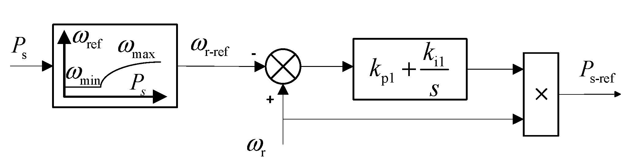
2.4. Transfer Function of Rotor Speed Control

When DFIG is in maximum power point tracking (MPPT) operation mode, each determined wind speed corresponds to a determined rotor speed so that the wind turbine outputs the maximum active power. The curve between the maximum active power and reference rotor speed value can be fitted through the least squares algorithm:
ω r - ref = { ω r min , P s < P s 1 a P s 2 + b P s + c , P s 1 P s P s 2 ω r max , P s > P s 2
where ωrmin, ωrmax, Ps1, and Ps2 represent the minimum and maximum value of the rotor speed and stator active power under the MPPT operating area, respectively; a, b, and c are the quadratic term fitting coefficients.
The control diagram of the DFIG rotor speed control is shown in Figure 4. The rotor speed control can control the stator active power reference command value in real time to track the maximum active power at the current wind speed. In Figure 4, kp1 and ki1 represent the proportional and integral coefficients of the rotor speed controller. The active power reference command value can be described by Figure 4:
P s - ref = ω r ( ω r ω r - ref ) ( k p 1 + k i 1 / s )
Linearizing Equations (8) and (9) at the stable operation point, the stator active power command value increment can be expressed as follows:
{ Δ ω r - ref = ( 2 a P s 0 + b ) Δ P s Δ P s - ref = [ ( 2 ω r 0 ω r - ref 0 ) Δ ω r ω r 0 Δ ω r - ref ] ( k p 1 + k i 1 / s ) .
Adding Equation (10) into Figure 3 to replace the input signal of the controller, the control diagram of DFIG stator active power with respect to the rotor speed can be obtained as follows.
As shown in Figure 5, when the subsynchronous damping control strategy is not considered, the transfer function of stator active power varying with rotor speed can be obtained according to the Mason formula:
Δ P s Δ ω r = U s L m G I ( 2 ω r 0 ω r - ref 0 ) ( s k p 1 + k i 1 ) ( s k p 2 + k i 2 ) s 2 L s + U s L m G I ( s k p 2 + k i 2 ) [ s + ω r 0 ( 2 a P s 0 + b ) ( s k p 1 + k i 1 ) ] .
When DFIG is not in the MPPT operating area, that is, the stator active power Ps < Ps1 or Ps > Ps2, the rotor speed reference value is constant and has nothing to do with the stator active power, which leads to the disappearance of the feedback branch in Figure 5. At this moment, Equation (11) is not applicable. At the subsynchronous frequency, the slip of the generator is negative, which causes the rotor equivalent resistance to be negative. When Ps < Ps1, the rotor speed is small in a low wind speed, which makes the slip become small and the rotor equivalent resistance become large. When the rotor equivalent negative resistance is larger than the sum of the stator resistance and the resistance in transmission lines at the resonance frequency, SSR will occur [5]. When Ps > Ps1, the rotor speed is the maximum value because of the high wind speed. The slip is a large negative value, so the rotor equivalent resistance becomes a small negative value. The total resistance of the DFIG system is positive, and the system can maintain stability when the perturbation occurs.

3. Results

3.1. Electrical Damping Expression

The complex torque coefficient method is used to determine whether SSR will occur at the subsynchronous frequency based on the sum of the mechanical and electrical damping coefficients of the generator [16,37]. Assuming that there is a small perturbation λ in the rotor rotating angular velocity, then the electromagnetic torque increment of the generator can be expressed as follows:
{ Δ T e = K e ( λ ) Δ δ + D e ( λ ) Δ ω Δ ω = j λ Δ δ
where Ke(λδ is the synchronous torque component related to the angular displacement and the transfer function Ke(λ) is the electrical synchronous torque coefficient; De(λω is the damping torque component related to the angular velocity; and the transfer function De(λ) is the electrical damping torque coefficient.
At subsynchronous frequency, if the sum of the electrical damping torque coefficient (De) and the mechanical damping torque coefficient (Dm) is less than zero, the system SSR will occur [38]. In general, the mechanical damping coefficient value of DFIG is much smaller than the electrical damping coefficient, so the mechanical damping effect of the wind turbine is ignored, and the SSR stability of the DFIG wind farm grid-connected system is evaluated based on the electrical damping coefficient [15].
There is an approximate relationship between the stator active power and electromagnetic torque as follows [37]:
T e n p P s / ω 1
where np is the number of pole pairs of the generator.
Substituting Equation (13) into Equation (11), the electrical damping coefficient can be described as follows:
Δ T e Δ ω r = n p U s L m G I ( 2 ω r 0 ω r - ref 0 ) ( s k p 1 + k i 1 ) ( s k p 2 + k i 2 ) ω 1 s 2 L s + ω 1 U s L m G I ( s k p 2 + k i 2 ) [ s + ω r 0 ( 2 a P s 0 + b ) ( s k p 1 + k i 1 ) ] = G Te ( s ) = Re [ G Te ( s ) ] + j Im [ G Te ( s ) ]
When the subsynchronous component of the angular frequency appears on the rotation speed of the DFIG grid-connected system, the electrical damping coefficient is the real part of the subsynchronous component from the electromagnetic torque gain according to Equations (12) and (14); that is, Re[GTe(er)]. According to the principle of the complex torque coefficient method, when the real part of the transfer function from electromagnetic torque is larger than zero, that is, Re[GTe(er)] > 0 or |∠GTe(er)| < 90°, the system electrical damping is positive, and the system can become stable after suffering a perturbation. On the contrary, when Re[GTe(er)] < 0 or |∠GTe(er)| > 90°, the system electrical damping become negative and the system will have risks of SSR. When the real part of the gain transfer function is equal to zero, that is Re[GTe(er)] = 0 or |∠GTe(er)| = 90°, the system electrical damping is equal to zero, and the electromagnetic torque of DFIG will produce the constant amplitude oscillation. At this moment, the angular frequency from the rotational speed is called the critical stable angular frequency. The DFIG system connected to a series complementary line can be equated to a second-order oscillation circuit, and the oscillation frequency of the system can be calculated. When this oscillation frequency is greater than the critical stability frequency, the electrical damping corresponding to the oscillation frequency is negative, which leads to the instability of the system.
When the DFIG operation conditions are determined, the electrical damping of the wind power system can be calculated according to the operating parameters of the wind turbine and subsynchronous resonance frequency of the series-compensated transmission lines. The advantage of the method is that it avoids the detailed mathematical modeling of the mechanical drive train which is necessary for eigenvalue analysis. At the same time, the proposed method can also realize the quantitative impact analysis of the wind speed, series compensation degrees, and controller parameters on the electrical damping characteristics of the wind power system. The analysis results can more accurately reflect the parameters sensitivity of SSR electrical damping.

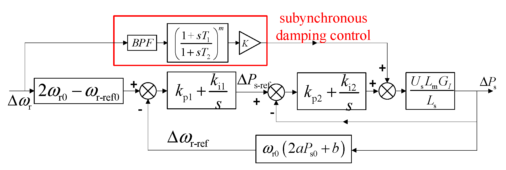
3.2. Design of Proposed Damping Controller

In order to supress the SSR of the DFIG-based wind farm grid-connected system, the most economical and feasible control strategy is to add a control loop in the converter controller. This method does not change the original control structure of the system, and the designed subsynchronous damping controller (SDC) will supress the subsynchronous oscillation only when the SSR occurs. The installed position of the SDC is shown in Figure 2. Since the proportional and integral coefficients of the RSC inner loop control have the highest sensitivity, so the SDC will have the best damping suppression when placed in the RSC inner loop control. What is more, considering that the frequency response characteristics of the electrical damping describes the dynamic relation between the electromagnetic torque and the rotor speed, so selecting the rotor speed as the input signal can more directly act on the electromagnetic and damp the subsynchronous oscillation.
As shown in Figure 2, the structure of the SDC consists of three parts: the band pass filter, the phase compensation, and the gain. The band pass filter is to extract the subsynchronous component signal appearing in the rotor speed. The phase compensation can compensate the phase of the input of the SDC. In general, the first-order phase compensation can meet the need of SDC [30].
After the SDC is added to the RSC inner-loop control shown in Figure 2, the transfer function of the stator active power with respect to the rotor speed can be obtained in Figure 5 through the deformation and derivation. According to the control diagram in Figure 5 and combining it with Formula (13), the transfer function with SDC between the electromagnetic torque and the rotor speed can be obtained as follows based on the Mason formula:
Δ T e Δ ω r = n p U s L m G I [ ( 2 ω r 0 ω r - ref 0 ) ( s k p 1 + k i 1 ) ( s k p 2 + k i 2 ) + s 2 G SDC ] ω 1 s 2 L s + ω 1 U s L m G I ( s k p 2 + k i 2 ) [ s + ω r 0 ( 2 a P s 0 + b ) ( s k p 1 + k i 1 ) ] = G Te - SDC ( s ) = Re [ G Te - SDC ( s ) ] + j Im [ G Te - SDC ( s ) ]
where GSDC represents the transfer function of SDC and GTe-SDC represents the transfer function between the electromagnetic torque and the rotor speed with SDC.
It is important to obtain the optimal parameters of the subsynchronous damping controller, so that the subsynchronous damping controller has the best subsynchronous oscillation suppression effect in a large subsynchronous frequency range. Thus, it is necessary to optimize the parameters of the subsynchronous damping controller according to Equation (15). Normally, when the system parameters vary, the range of the system subsynchronous frequency changes is not very large. The calculation results of the eigenvalues in the literature [17] indicate that even if the series compensation degree varies from 40% to 60%, the varying range of the subsynchronous resonance frequency is about 6 Hz. At the same time, the subsynchronous oscillation frequency of the DFIG-based wind farm grid-connected system model established in this paper is around 35 Hz, so the cut-off frequency of the band pass filter is selected to be 35 Hz. The bandwidth does not exceed 6 Hz, which is enough to cover the subsynchronous resonance frequency change range brought by parameter changes under large operating conditions.
After determining the cut-off frequency of the band pass filter, the wind speed, the series compensation degree, and controller parameters of the system can be obtained by setting an operation scene of the DFIG-based wind farm. The optimal controller parameters of the subsynchronous damping controller can be obtained by solving the mathematical optimization model shown in Equation (16). The objective function of Equation (16) is to make the system have the largest electrical damping in this scenario and have the best subsynchronous oscillation suppression effect.
{ max Re [ G Te - S D C ( j ω er , ξ , T 1 , T 2 , K ) ] s . t . ξ ω c = π B 0 < B 6 T 1 , T 2 > 0 K > 0
where ωc and B represent the cut-off frequency and the bandwidth; T1 and T2 represent the leading and lagging phase compensation parameters; and K represents the parameter of the gain link.
In order to obtain the optimal solution of the parameters of the mathematical optimization model shown in Equation (16), particle swarm optimization is used to solve the mathematical optimization model. By setting the appropriate particle population number, initial weight, and the learning factor parameters, the optimal parameters in this scenario can be obtained after multiple iterations. In order to make the optimal parameters of the subsynchronous damping controller more robust, a number of different DFIG-based wind farm operating scenarios are set. An optimal set of parameters can be obtained in each DFIG-based wind farm operating scenario. By comparing the changes in system electrical damping brought by the optimal parameters in each scenario, the optimal parameters of the subsynchronous damping controller in all operating scenarios are selected.
The initial operating conditions of the system are set as follows: the wind speed is 8 m/s; the series compensation degree is 20%; kp1, kp2, and kp3 are 1.3, 1.6, and 0.47 p.u., respectively; ki1, ki2, and ki3 are 20, 40, and 10 p.u., respectively. The cut-off frequency of the band pass filter is set to 35 Hz. The number of the particle population n is 100. The maximum number of the iterations tmax is 200. The initial inertial weight ω is 0.6. The learning factors c1 and c2 are both 0.5. The upper and lower speed limits are 20 and −20, respectively. After iterative calculation based on changing the system operating conditions many times, the optimal parameters of the subsynchronous damping controller are finally obtained as follows: ξ = 0.07142, T1 = 0.01, T2 = 0.001, K = 17.
Figure 6 shows the frequency response characteristics of SSR electrical damping with and without SDC. It is obvious that the system critical stable angular frequency shifts to the right when the SDC is added to the RSC controller. Compared to the system without SDC, the system electrical damping with SDC is positive at the range of 69 to 80 rad/s, which indicates that the system is stable with SDC. Meanwhile, when the angular frequency is lower than 69 rad/s, the system with SDC has higher electrical damping than that without SDC. Therefore, the designed SDC can improve the electrical damping and the system stability of the DFIG-based wind farm grid-connected system.

4. Discussion

4.1. Description of Analysis and Simulation Parameters Setting

The general conclusion in the existing studies is that conditions of higher string complementarity lead to SSR production. Generally, under normal operating conditions of wind farms, the line string complementarity does not reach the degree so that SSR occurs less in actual wind farms. In order to study the influence of relevant parameters on SSR, the numerical design of parameters is close to the critical value in the following analysis and simulation. In this case, SSR is easier to generate than the actual wind farm.

4.2. Impact Parameters and Sensitivity Analysis

According to the Equation (14), the frequency response characteristic of the DFIG system electrical damping in all subsynchronous frequency ranges can be calculated, and the effects of the wind speed, series compensation, and various controller parameters on SSR electrical can be further quantified and analyzed. The parameters adopted in the following analysis are shown in Table A1 and Table A2 in Appendix A. When any one parameter is changed, we keep the other operating parameters constant.

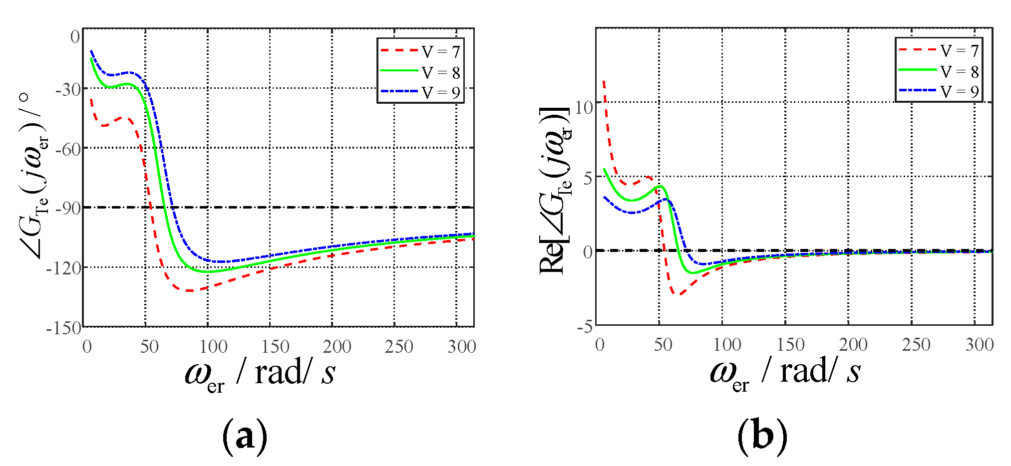
4.2.1. Impact of Wind Speed on SSR Electrical Damping

Under different wind speeds, the real part and phase of the transfer function from the electromagnetic torque with respect to the rotation speed perturbation subsynchronous components are shown in Figure 7. In Figure 7, with the increase of the angular frequency, the phase of the transfer function gradually falls from zero to below negative ninety, and the real part of the gain gradually decreases from positive to below zero. This result shows that as the subsynchronous angular frequency increases (ωer), the system stable phase margin and electrical damping decrease, and the SSR stability of the system gradually deteriorates. On the other hand, under the same angular frequency, the higher the wind speed, the larger the phase and the real part of the transfer function, indicating that the greater the stable phase margin and the electrical damping, the better the system SSR stability. In addition, the critical stable angular frequency (ωer0) of the system electrical damping increases with the increase of the wind speed. This result shows that at high wind speed, only when a higher series compensation capacitor is connected to the transmission line can SSR be induced, which verifies the result that higher the wind speed, the better the system SSR stability.

4.2.2. Impact of Controller Parameters on SSR Electrical Damping

Figure 8 shows the impact of the proportional coefficient (kp3) and integral coefficient (ki3) from the RSC inner loop controller on SSR electrical damping. In Figure 8a, when the angular frequency is lower than 54.5 rad/s, the phase of the electromagnetic torque does not change much with kp3 increasing; when the angular frequency is higher than 54.5 rad/s, the larger the kp3, the smaller the phase. These results indicate that the system stable phase margin decreases with the increase of kp3. In Figure 8b, when the angular frequency is at the range of the 24 to 59 rad/s, the real part of the electromagnetic torque increases with the increase of kp3, but the system electrical damping is all positive, and the system is stable. When the angular frequency is higher than 59 rad/s, as kp3 increases, the real part of the electromagnetic torque and the critical stable angular frequency are smaller. These results show that the larger the kp3, the smaller the system electrical damping and the worse the system SSR stability.
As shown in Figure 8c,d, when the angular frequency is less than 70 rad/s, the larger the ki3, the larger the system stable phase margin and electrical damping. When the angular frequency is higher than 70 rad/s, the phase and the real part of the electromagnetic torque decreases with the increase of ki3. However, the system electrical damping is negative at this moment, and increasing ki3 will only make the system SSR stability worse.
The effects of rotor speed controller and RSC outer loop controller parameters on SSR electrical damping are similar to the RSC inner loop controller parameters. The smaller the proportional coefficients of the controller and the larger the integral coefficients, the larger the system electrical damping and the better the system SSR stability.

4.2.3. The Sensitivity of the Controller Parameters

Although the proportional parameters of rotor speed control and RSC control have similar trends in the impact of SSR electrical damping and the integral parameters also have similar trends in the impact of SSR electrical damping, the sensitivity of different parameters to SSR electrical damping differs. In order to quantify the degree of the influence of the controller parameters on SSR electrical damping, the sensitivity index of the controller parameters to the SSR electrical damping is defined as follows:
d D e d X = Re [ G Te ( s , X + Δ X ) ] Re [ G Te ( s , X ) ] Δ X
where X represents the controller parameters in rotor speed control and RSC. ΔX represents the represents the small change amount of the controller parameters, and Re[GTe(s,X)] represents the system electrical damping.
According to Formula (17), the sensitivity of different controller parameters on SSR electrical damping can be quantified. The parameters of the selected point for the sensitivity analysis are shown in Table A2 in Appendix A. Taking ΔX as equal to 0.01, the sensitivity of the controller parameters of the rotor speed control, RSC outer loop control, and the RSC inner loop control in all subsynchronous frequency ranges is shown in Figure 9. It can be seen from Figure 9 that the sensitivity of the proportional coefficient of the RSC inner loop control is highest, which is significantly higher than other proportional and integral coefficients. The sensitivity of the proportional coefficients of the RSC outer loop and rotor speed control is not much different. The sensitivity of the proportional coefficients of all controllers has a maximum value near the critical stable angular frequency. The sensitivity of the rotor speed control proportional coefficient is negative, which indicates that the SSR electrical damping decreases with the increase of the kp1. The sensitivities of kp2 and kp3 are positive in the range of 24 to 59 rad/s. In this range, the system electrical damping itself is positive, indicating that increasing the proportional coefficient at this range can increase the system stability. When the angular frequency is higher than 59 rad/s, the sensitivities of kp2 and kp3 are negative, which indicate that increasing the proportional coefficients at this range will decrease the SSR electrical damping and make the system unstable.
Figure 9b shows the sensitivity of the integral coefficients of the speed control, RSC outer loop control, and inner loop control in different subsynchronous frequency ranges. It can be seen that the integral coefficient of the RSC inner loop control has the highest sensitivity. The integral coefficient sensitivity of each controller has a maximum value near the critical stable angular frequency. In the range of 44 to 70 rad/s, the sensitivities of the integral coefficients are positive, which indicate that the larger the integral coefficients, the larger the SSR electrical damping. When the angular frequency is higher than 70 rad/s, the sensitivities of the integral coefficients become negative, which indicate that increasing the integral coefficients will decrease the SSR electrical damping.

4.2.4. Comparison with Other Literature Results

Studies analyzing SSR-related factors in different ways also exist in the past research work. In [39], the SSR of DFIG is related to wind speed, series compensation degree, and RSC parameters by the complex vector method with impedance analysis. In [19], the participation factors of SSR-related modalities were analyzed using the eigenvalue method. The analysis shows that the SSR is most dependent on the rotor current, and the control parameters of the rotor-side current loop have a great influence on the SSR mode. The results in this paper show that the stability of SSR decreases with decreasing wind speed, increasing the series compensation degree, increasing the proportionality factor, and decreasing the integration factor in the rotor speed controller and rotor-side converter. The results of the sensitivity analysis show that the current inner loop parameter has the greatest influence. These results are consistent with existing studies.

4.3. Time-Domain Simulation Verification

In order to verify the correctness of the SSR electrical damping characteristic analysis and the effectiveness of the designed SDC, a simulation model of the DFIG-based wind farm grid-connected system with a series-compensated transmission line is built in PSCAD/EMTDC. The parameters adopted in the simulation are shown in Table A1 and Table A2 in Appendix A. The initial compensation degree is 15%. In the simulation, the fixed series compensation capacitor is set to change from the initial bypass operation to online operation at 15 s. When any one parameter is changed, the other operating parameters are kept constant.
When the wind speed and the compensation degree vary, the response curves of the electromagnetic torque are shown in Figure 10. In Figure 10a, when the wind speed is 7 m/s, the electromagnetic torque will diverge rapidly after a small perturbation. When the wind speed rises to 8 m/s, the electromagnetic torque will produce a constant amplitude after a small perturbation. When the wind speed is 9 m/s, the electromagnetic torque will converge gradually to a stable state. However, in Figure 10b, the higher the compensation degree, the more unstable the electromagnetic torque. Therefore, the higher the wind speed and the lower the compensation degree, the better the stability of the DFIG-based wind farm grid-connected system, which result is consistent with the previous analysis of the system electrical damping.
Figure 11 shows the response curves of electromagnetic torque when the RSC inner-loop proportional and integral coefficients vary. It can be seen from the figure that the smaller the proportional coefficient and the larger the integral coefficient, the easier it is for the electromagnetic torque to converge to a stable state. Meanwhile, the change range of the proportional coefficient is smaller than that of the integral coefficient, but it is easier to change from the divergent state to the stable state, which is a result that indicates that the sensitivity of the proportional coefficient is higher than the integral coefficient. The above analysis results are consistent with the previous analysis results of the system’s electrical damping.
Figure 12 shows the dynamic response curves of the electromagnetic torque with and without the SDC under different operating conditions. The wind speed is 8 m/s for all operating conditions. In Figure 12a, when the compensation degree is 20%, the system electrical damping is too low, causing the electromagnetic torque to rapidly diverge after a small perturbation without SDC. However, the electromagnetic torque quickly converges to a stable state with the SDC added in the RSC controller. Figure 12b,c show that the large proportional coefficient and the small integral coefficient will deteriorate the system’s stability. At the same time, the electromagnetic torque will rapidly diverge without the SDC. However, when the SDC is included, the electromagnetic torque will quickly converge, and the SSR is effectively suppressed. When the proportional coefficient of the rotor speed controller is 1.3, it can be seen in Figure 12d that the electromagnetic torque can gradually converge to stable with the SDC. However, after the SDC is installed in the RSC inner-loop controller, the electromagnetic torque can converge to a stable state faster than that without the SDC.
From the above analysis, it can be seen that the SDC proposed in this paper can effectively suppress the SSR caused by the DFIG-based wind farm grid-connected system with series-compensated transmission lines under different operating conditions.

5. Conclusions

This paper proposes the expression of the electrical damping, which is used for analyzing the SSR of the series-compensated DFIG-based wind farm grid-connected system based on the complex torque coefficient method. Based on this expression, the effects of the wind speed, compensation degree, and the controller parameters on the stability of the system SSR are quantitatively analyzed. Meanwhile, the SDC strategy is proposed and optimized by the PSO algorithm. The damping effect of optimal SDC is analyzed through the expression of the SSR electrical damping characteristics. Finally, the correctness of the electrical damping analysis and the effectiveness of the SDC strategy are verified by PSCAD/EMTDC time-domain simulation. The analysis results show that the higher the wind speed, the lower the compensation degree, the smaller the proportional coefficient of the controller, and the larger the integral coefficient, the greater the electrical damping and the better the system stability. Moreover, the proposed SDC strategy can effectively suppress the system SSR under different operating conditions.

Author Contributions

Conceptualization, X.P. and J.Z.; methodology, X.P. and R.C.; software, S.Q.; validation, X.P., J.Z. and R.C.; formal analysis, X.P.; investigation, J.Z. and R.C.; resources, S.Q. and H.S.; data curation, X.P.; writing—original draft preparation, X.P. and J.Z.; writing—review and editing, R.C.; visualization, J.Z. and R.C.; supervision, S.Q., H.S. and R.B.; project administration, S.Q., H.S. and R.B.; funding acquisition, X.P. All authors have read and agreed to the published version of the manuscript.

Funding

This work was supported in part by the National Key Research and Development Program of China under Grant 2018YFB0904000 (Corresponding author: Xiaotao Peng).

Conflicts of Interest

The authors declare no conflict of interest.

Appendix A

Table A1. Parameters of the DFIG wind farm.
ParametersValue
Rated power200 MW
Rated voltage690 V
Ls(p.u.)4.60
Lr(p.u.)4.61
Lm(p.u.)4.50
Rs(p.u.)0.0054
Rr(p.u.)0.00607
Dm(p.u.)0.01
Table A2. Parameters of controllers.
ParametersValue
kp1(p.u.)1.5
ki1(p.u.)10
kp2(p.u.)1.8
ki2(p.u.)20
kp3(p.u.)0.5
ki3(p.u.)2.0

References

  1. Kundur, P. Power System Stability and Control; McGraw-Hill: New York, NY, USA, 1994. [Google Scholar]
  2. Adams, J.; Pappu, V.A.; Dixit, A. Ercot experience screening for Sub-Synchronous Control Interaction in the vicinity of series capacitor banks. In Proceedings of the 2012 IEEE Power and Energy Society General Meeting, San Diego, CA, USA, 22–26 July 2012; pp. 1–5. [Google Scholar]
  3. Mohammadpour, H.A.; Santi, E. Analysis of subsynchronous control interactions in DFIG-based wind farms: ERCOT case study. In Proceedings of the 2015 IEEE Energy Conversion Congress and Exposition, Montreal, QC, Canada, 20–24 September 2015; pp. 500–505. [Google Scholar]
  4. Wang, L.; Xie, X.; Jiang, Q.; Liu, H.; Li, Y.; Liu, H. Investigation of SSR in practical DFIG-based wind farms connected to a series-compensated power system. IEEE Trans. Power Syst. 2015, 30, 2772–2779. [Google Scholar] [CrossRef]
  5. Fan, L.; Kavasseri, R.; Miao, Z.; Zhu, C. Modeling of DFIG-based wind farms for SSR analysis. IEEE Trans. Power Del. 2010, 25, 2073–2082. [Google Scholar] [CrossRef]
  6. Fan, L.; Zhu, C.; Miao, Z.; Hu, M. Modal analysis of a DFIG-based wind farm interfaced with a series compensated network. IEEE Trans. Energy Convers. 2011, 26, 1010–1020. [Google Scholar] [CrossRef]
  7. Mohammadpour, H.A.; Santi, E. Modeling and control of gate-controlled series capacitor interfaced with a DFIG-based wind farm. IEEE Trans. Ind. Electron. 2015, 62, 1022–1033. [Google Scholar] [CrossRef]
  8. Mishra, Y.; Mishra, S.; Tripathy, M.; Senroy, N.; Dong, Z. Improving stability of a DFIG-based wind power system with tuned damping controller. IEEE Trans. Energy Convers. 2009, 24, 650–660. [Google Scholar] [CrossRef]
  9. ABB. Series Compensation Boosting Transmission Capacity; Reference Case Study; ABB: Zürich, Switzerland, 2010. [Google Scholar]
  10. Sun, J. Impedance-based stability criterion for grid-connected inverters. IEEE Trans. Power Electron. 2011, 26, 3075–3078. [Google Scholar] [CrossRef]
  11. Sun, J. Small-signal methods for ac distributed power systems. IEEE Trans. Power Electron. 2009, 24, 2545–2554. [Google Scholar]
  12. Miao, Z. Impedance-model-based SSR analysis for type 3 wind generator and series-compensated network. IEEE Trans. Energy Convers. 2012, 27, 984–991. [Google Scholar] [CrossRef]
  13. Piyasinghe, L.; Miao, Z.; Khazaei, J.; Fan, L. Impedance model-based SSR analysis for TCSC compensated Type-3 wind energy delivery systems. IEEE Trans. Sustain. Energy 2015, 6, 179–187. [Google Scholar] [CrossRef]
  14. Liu, H.; Xie, X.; Li, Y.; Liu, H.; Hu, Y. A small-signal impedance method for analyzing the SSR of series-compensated DFIG-based wind farms. In Proceedings of the 2015 IEEE Power & Energy Society General Meeting, Denver, CO, USA, 26–30 July 2015; pp. 1–5. [Google Scholar]
  15. Badrzadeh, B.; Sahni, M.; Zhou, Y.; Muthumuni, D.; Gole, A. General methodology for analysis of sub-synchronous interaction in wind power plants. IEEE Trans. Power Syst. 2013, 28, 1858–1869. [Google Scholar] [CrossRef]
  16. Chowdhury, M.A.; Shafiullah, G.M. SSR mitigation of series-compensated DFIG wind farms by a nonlinear damping controller using partial feedback linearization. IEEE Trans. Power Syst. 2018, 33, 2528–2538. [Google Scholar] [CrossRef]
  17. Huang, P.; Moursi, M.S.E.I.; Xiao, W.; Kirtley, J.L. Subsynchronous resonance mitigation for series-compensated DFIG-Based wind farm by using two-degree-of-freedom control strategy. IEEE Trans. Power Syst. 2015, 30, 1442–1454. [Google Scholar] [CrossRef]
  18. Azizi, A.H.; Rahimi, M. Analytical assessment of subsynchronous resonance (SSR) impact on doubly fed induction generator wind turbine behavior and efficient suppression of SSR oscillations. Int. Trans. Electr. Energy Syst. 2021, 31, e12798. [Google Scholar] [CrossRef]
  19. Yang, J.-W.; Sun, X.-F.; Chen, F.-H.; Liao, K.; He, Z.-Y. Subsynchronous resonance suppression strategy for doubly fed induction generators based on phase-shift average of rotor current. Int. Trans. Electr. Energy Syst. 2019, 29, e2831. [Google Scholar] [CrossRef]
  20. Jannaty, B.H.; Marc, B. Suppression of Sub-Synchronous Resonances Through Excitation Control of Doubly Fed Induction Generators. IEEE Trans. Power Syst. 2019, 34, 4329–4340. [Google Scholar]
  21. Chen, A.; Xie, D.; Zhang, D.; Gu, C.; Wang, K. PI Parameter Tuning of Converters for Sub-Synchronous Interactions Existing in Grid-Connected DFIG Wind Turbines. IEEE Trans. Power Electron. 2019, 34, 6345–6355. [Google Scholar] [CrossRef]
  22. Liu, H.; Xie, X.; Li, Y.; Liu, H.; Hu, Y. Mitigation of SSR by embedding subsynchronous notch filters into DFIG converter controllers. IET Gener. Transm. Distrib. 2017, 11, 2888–2896. [Google Scholar] [CrossRef]
  23. Liu, H.; Xie, X.; He, J.; Liu, H.; Li, Y. Damping DFIG-associated SSR by Adding Subsynchronous Suppression Filters to DFIG Converter Controllers. In Proceedings of the IEEE-Power-and-Energy-Society General Meeting, Boston, MA, USA, 17–21 July 2016. [Google Scholar]
  24. Meng, Y.; Pan, X.; Ma, H.; Li, K.; Yu, J.; Wang, X. Analysis and mitigation of subsynchronous resonance based on integral control for DFIG-based wind farm. IET Gener. Transm. Distrib. 2019, 13, 1718–1725. [Google Scholar] [CrossRef]
  25. He, H.; Lv, D.; Wen, L.; Geng, H.; Gao, J. Analysis and Suppression Strategies of Sub-synchronous Resonance on DFIG. In Proceedings of the IEEE International Power Electronics and Application Conference and Exposition, Shenzhen, China, 4–7 November 2018; pp. 1016–1020. [Google Scholar]
  26. Mohammadpour, H.A.; Santi, E. SSR damping controller design and optimal placement in rotor-side and grid-side converters of series compensated DFIG-based wind farm. IEEE Trans. Sustain. Energy 2015, 6, 388–399. [Google Scholar] [CrossRef]
  27. Li, N.; Wang, L.; Yang, H.; Ma, H. Stability Analysis for SSR of DFIG-Based Wind Farm Considering STATCOM Capacity Constraint. In Proceedings of the 22nd International Conference on Electrical Machines and Systems, Harbin, China, 11–14 August 2019; pp. 1576–1581. [Google Scholar]
  28. Viqar, Y.; Aijaz, A. Unit Template Based Control Design for Alleviation and Analysis of SSR in Power System Using STATCOM. Electr. Power Compon. Syst. 2019, 47, 1805–1813. [Google Scholar]
  29. Yao, J.; Wang, X.; Li, J.; Liu, R.; Zhang, H. Sub-synchronous resonance damping control for series-compensated DFIG-based wind farm with improved particle swarm optimization algorithm. IEEE Trans. Energy Convers. 2019, 34, 849–859. [Google Scholar] [CrossRef]
  30. Leon, A.E. Integration of DFIG-based wind farms into series compensated transmission systems. IEEE Trans. Sustain. Energy 2016, 7, 451–460. [Google Scholar] [CrossRef]
  31. Varma, R.K.; Auddy, S.; Semsedini, Y. Mitigation of subsynchronous resonance in a series-compensated wind farm using FACTS controllers. IEEE Trans. Power Del. 2008, 23, 1645–1654. [Google Scholar] [CrossRef]
  32. Moharana, A.; Varma, R.; Seethapathy, R. SSR alleviation by STATCOM in induction-generator-based wind farm connected to series compensated line. IEEE Trans. Sustain. Energy 2014, 5, 947–957. [Google Scholar] [CrossRef]
  33. Li, W.; Dinh-Nhon, T. Stability enhancement of a power system with a PMSG-based and a DFIG-based offshore wind farm using a SVC with an adaptive-network-based fuzzy inference system. IEEE Trans. Ind. Electron. 2013, 60, 2799–2807. [Google Scholar]
  34. Fernandez, L.M.; Jurado, F.; Saenz, J.R. Aggregated dynamic model for wind farms with doubly fed induction generator wind turbines. Renew. Energy 2008, 33, 129–140. [Google Scholar] [CrossRef]
  35. Liu, H.; Xie, X.; Zhang, C.; Li, Y.; Hu, Y. Quantitative SSR analysis of series-compensated DFIG-Based wind farms using aggregated RLC circuit model. IEEE Trans. Power Syst. 2017, 32, 474–483. [Google Scholar] [CrossRef]
  36. Kovacs, P.K. Transient Phenomena in Electrical Machines; Elsevier: New York, NY, USA, 1984. [Google Scholar]
  37. Abad, G.; Lopez, J.; Rodriguez, M.; Marroyo, L.; Iwanski, G. Doubly Fed Induction Machine: Modeling and Control for Wind Energy Generation; Wiley: Hoboken, NJ, USA, 2011. [Google Scholar]
  38. Zhu, X.; Sun, H.; Wen, J.; Cheng, S. Improved complex torque coefficient method using CPCM for multi-machine system SSR analysis. IEEE Trans. Power Syst. 2014, 29, 2060–2068. [Google Scholar] [CrossRef]
  39. Zhang, X.; Zhang, Y.; Fang, R.; Xu, D. Impedance Modeling and SSR Analysis of DFIG Using Complex Vector Theory. IEEE Access 2019, 3, 155860–155870. [Google Scholar] [CrossRef]
Figure 1. Double-fed inductive generator (DFIG) wind farm grid-connected system.
Electronics 10 01640 g001
Figure 2. Control diagram of rotor-side converter (RSC).
Electronics 10 01640 g002
Figure 3. Control diagram of DFIG stator active power.
Electronics 10 01640 g003
Figure 4. Control diagram of DFIG rotor speed control.
Electronics 10 01640 g004
Figure 5. Control diagram of DFIG stator active power varying with rotor speed.
Electronics 10 01640 g005
Figure 6. Comparison of subsynchronous damping controller effects.
Electronics 10 01640 g006
Figure 7. Frequency response of the gain of ΔTe under different wind speeds: (a) phase vary with ωer; (b) real part vary with ωer.
Electronics 10 01640 g007
Figure 8. Frequency response of the gain of ΔTe under different control parameters of RSC current control loop: (a) phase vary with ωer under kp3; (b) real part vary with ωer under kp3; (c) phase vary with ωer under ki3; (d) real part vary with ωer under ki3.
Electronics 10 01640 g008
Figure 9. Electrical damping sensitivity of system under different proportional and integral parameters: (a) proportional coefficients; (b) integral coefficients.
Electronics 10 01640 g009
Figure 10. Electromagnetic torque at different wind speeds and compensation degrees: (a) different wind speed; (b) different compensation degree.
Electronics 10 01640 g010
Figure 11. Electromagnetic torque in different RSC inner-loop proportional and integral coefficients: (a) different kp3; (b) different ki3.
Electronics 10 01640 g011
Figure 12. Effect comparison of the system with and without SDC under different operating conditions: (a) compensation degree of 20%; (b) kp3 = 0.52; (c) ki3 = 1; (d) kp1 = 1.3.
Electronics 10 01640 g012
Publisher’s Note: MDPI stays neutral with regard to jurisdictional claims in published maps and institutional affiliations.

