
Quad Sector HMSIW Tapered Slot Antenna Array for Millimeter-Wave Applications


Abstract
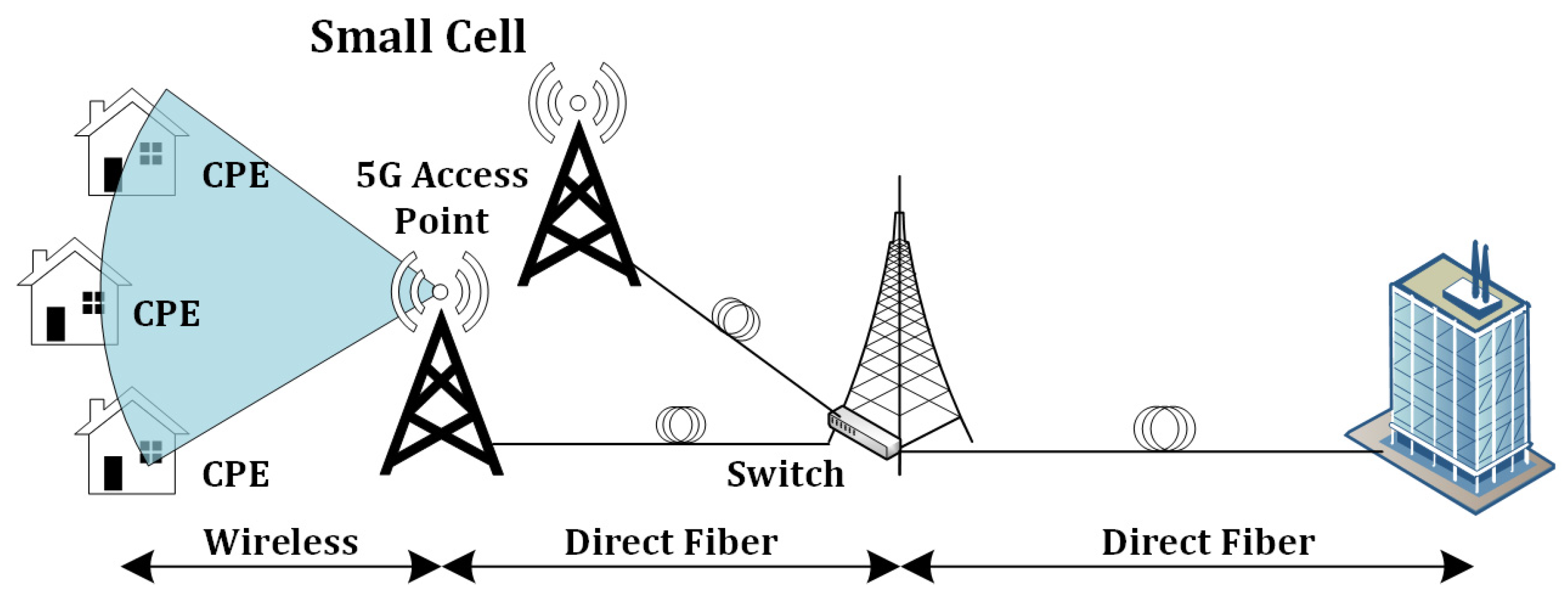
:1. Introduction
2. Design Procedure
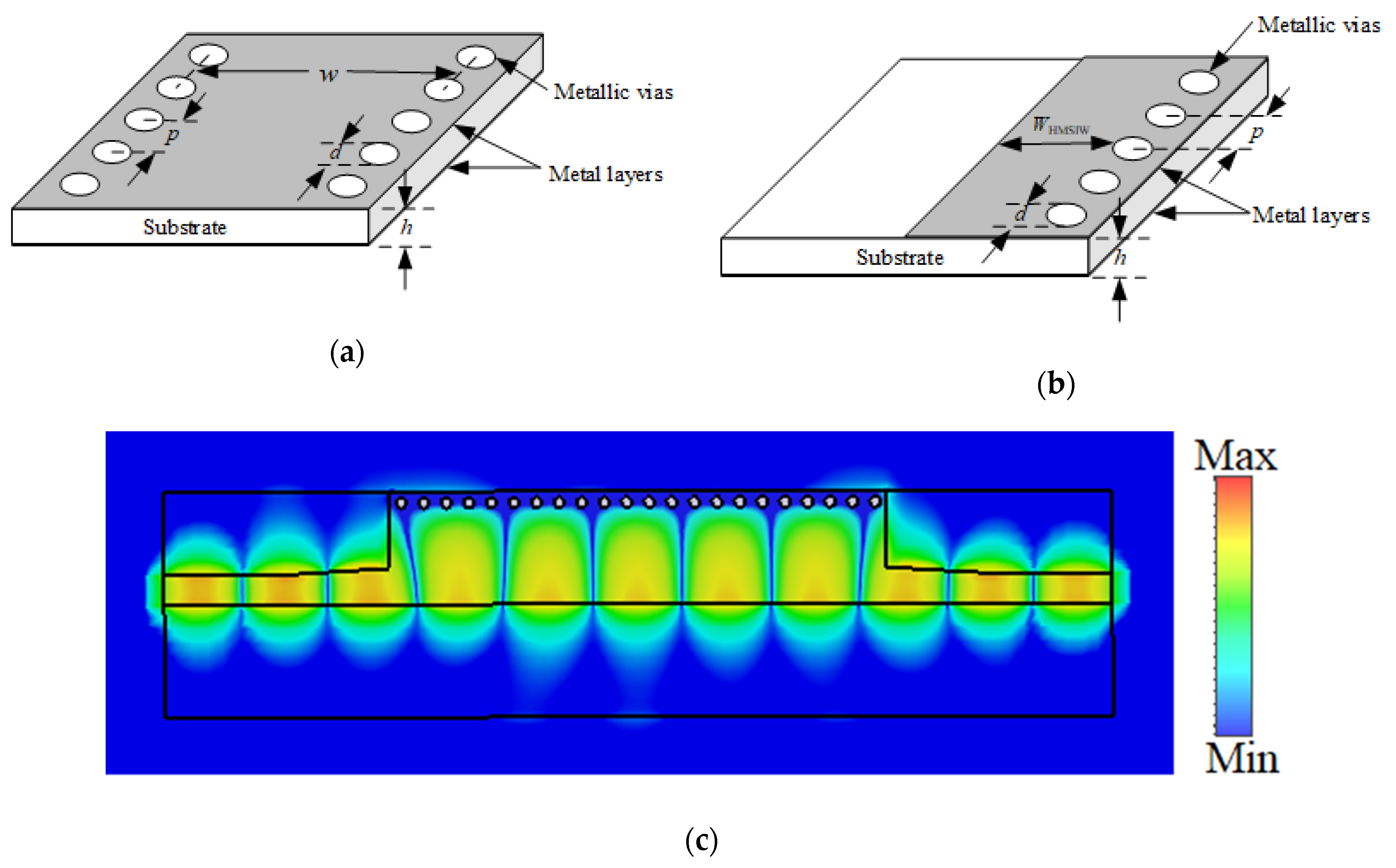
2.1. Design of HMSIW
2.2. Radiation Principle of Slot Pair
2.3. HMSIW Single Slot Antenna and in an Array Configuration
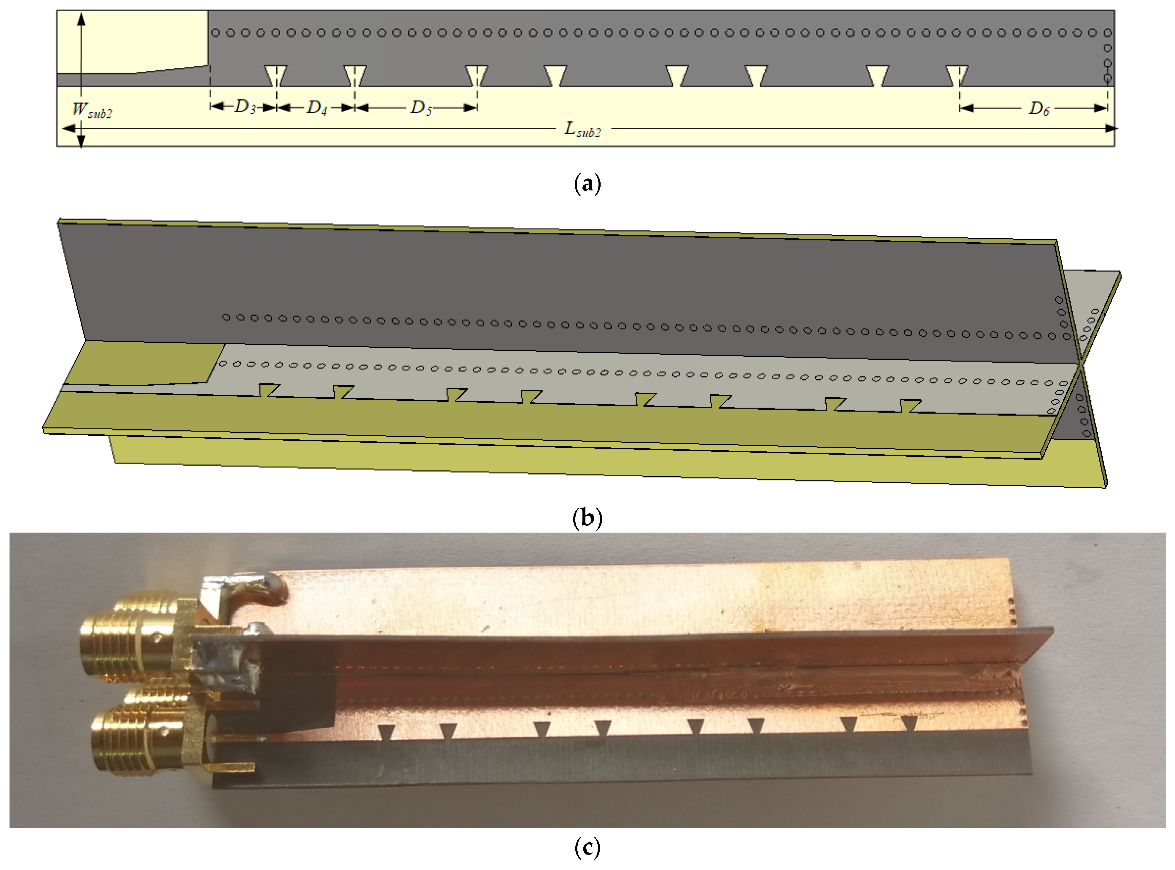
3. Quad Sector HMSIW Slot Antenna Array
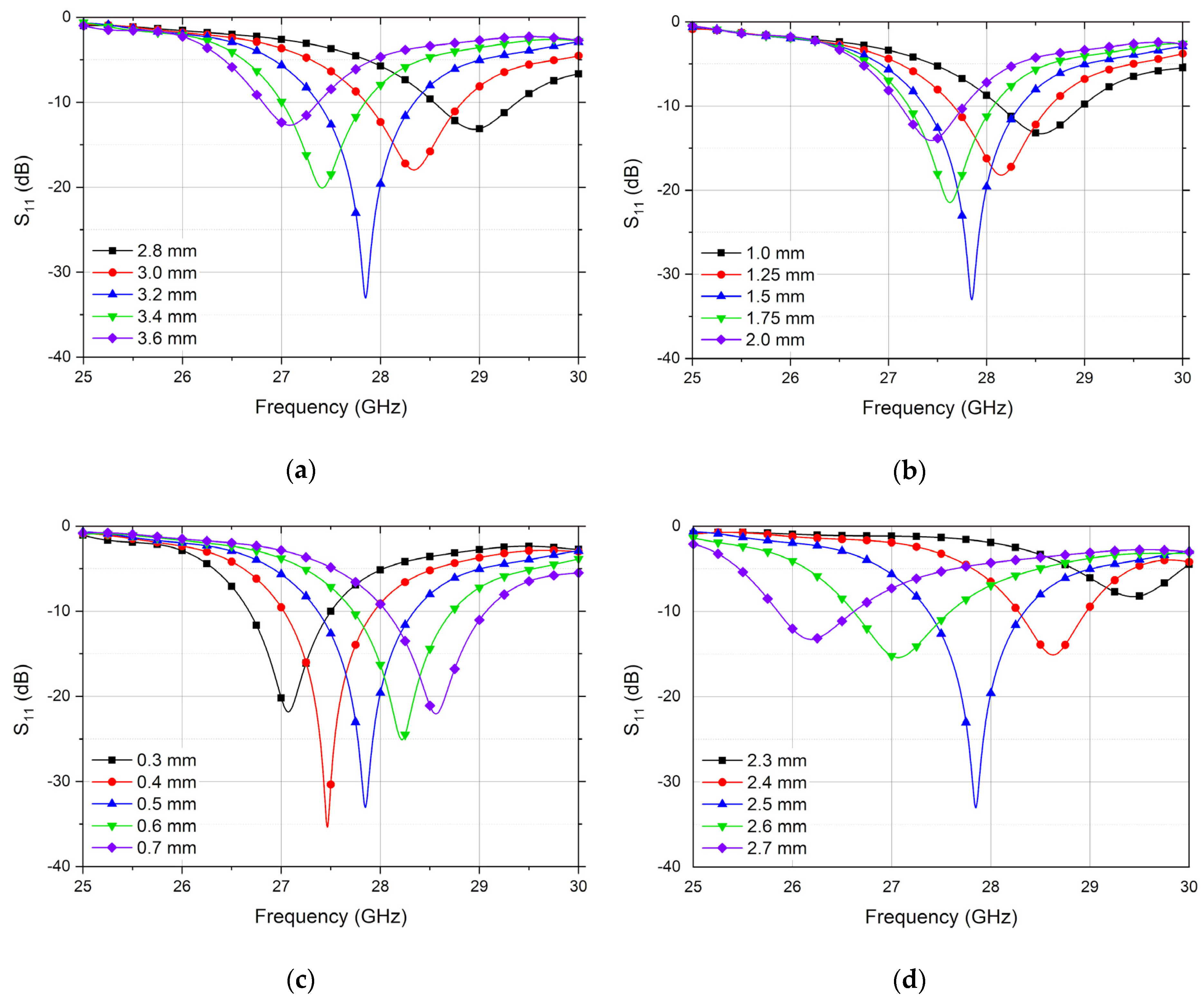
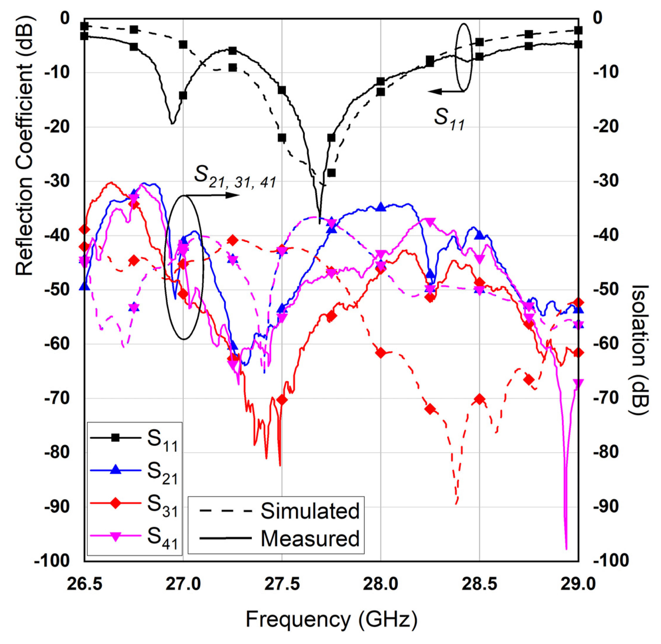
3.1. S-Parameters
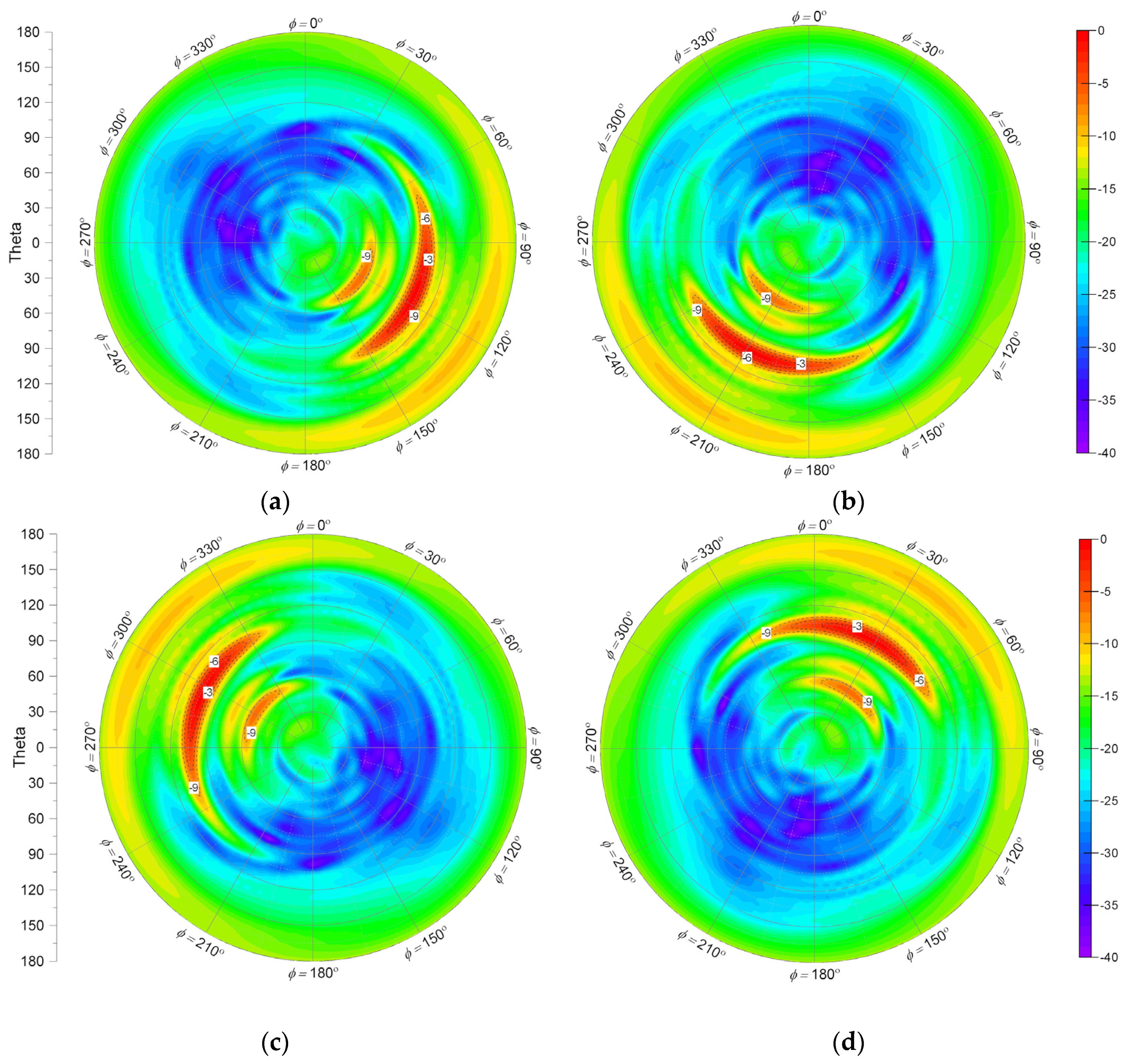
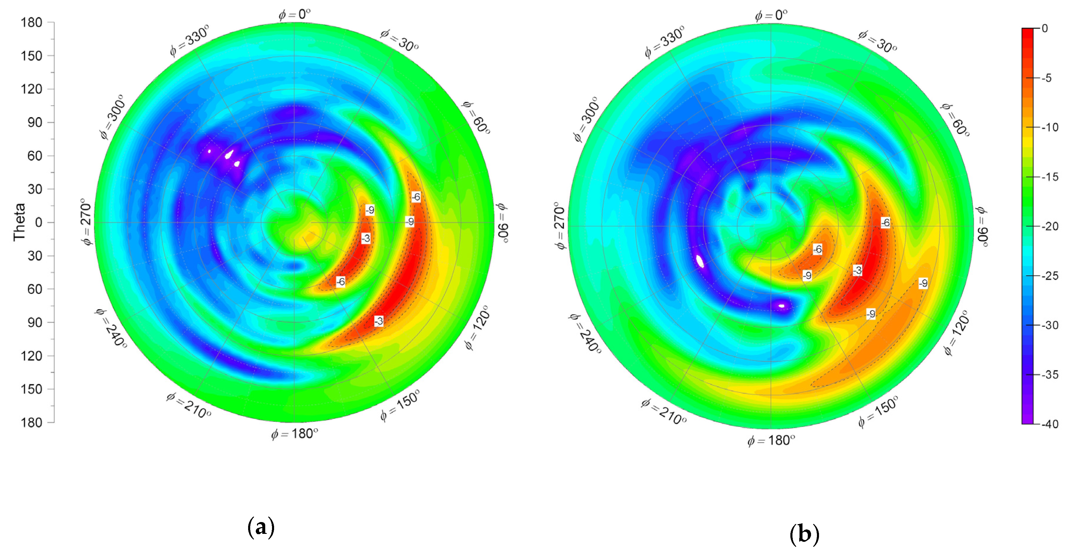
3.2. Radiation Performance
4. Conclusions
Author Contributions
Funding
Conflicts of Interest
References
- Rappaport, T.S.; Sun, S.; Mayzus, R.; Zhao, H.; Azar, Y.; Wang, K.; Wong, G.N.; Schulz, J.K.; Samimi, M.; Gutierrez, F. Millimeter Wave Mobile Communications for 5G Cellular: It Will Work! IEEE Access 2013, 1, 335–349. [Google Scholar] [CrossRef]
- International Telecommunication Union: Setting the Scene for 5G: Opportunities & Challenges. Available online: https://www.itu.int/en/ITU-D/Documents/ITU_5G_REPORT-2018.pdf (accessed on 12 June 2021).
- Topyan, K.; Ulema, M. Architectural and financial considerations for deploying 5G based fixed wireless access. In Proceedings of the 2020 IEEE International Black Sea Conference on Communications and Networking (BlackSeaCom), Odessa, Ukraine, 26–29 May 2020; pp. 1–6. [Google Scholar]
- Xie, W.; Mao, N.; Rundberget, K. Cost comparisons of backhaul transport technologies for 5G fixed wireless access. In Proceedings of the 2018 IEEE 5G World Forum (5GWF), Santa Clara, CA, USA, 9–11 July 2018; pp. 159–163. [Google Scholar]
- Morais, D.H. Key 5G Physical Layer Technologies: Enabling Mobile and Fixed Wireless Access, 1st ed.; Springer International Publishing: Berlin, Germany, 2020; p. 284. [Google Scholar]
- Laraqui, K.; Tombaz, S.; Furuskär, A.; Skubic, B.; Nazari, A.; Trojer, E. Fixed Wireless Access on a Massive Scale with 5G. Available online: https://www.ericsson.com/en/reports-and-papers/ericsson-technology-review/articles/fixed-wireless-access-on-a-massive-scale-with-5g (accessed on 12 June 2021).
- FCC mmWave R&O and FNPRM. Available online: https://mentor.ieee.org/802.18/dcn/16/18-16-0058-00-0000-fcc-mmwave-r-o-and-fnprm.pdf (accessed on 8 March 2021).
- Deslandes, D.; Wu, K. Integrated microstrip and rectangular waveguide in planar form. IEEE Microw. Wirel. Compon. Lett. 2001, 11, 68–70. [Google Scholar] [CrossRef]
- Rengarajan, S.R.; Josefsson, L.G.; Elliott, R.S. Waveguide-fed slot antennas and arrays: A review. Electromagnetics 2007, 19, 3–22. [Google Scholar] [CrossRef]
- Grigoropoulos, N.; Young, P.R. Compact folded waveguides. In Proceedings of the 34th European Microwave Conference, Amsterdam, The Netherlands, 12–14 October 2004; pp. 973–976. [Google Scholar]
- Grigoropoulos, N.; Sanz-Izquierdo, B.; Young, P.R. Substrate integrated folded waveguides (SIFW) and filters. IEEE Microw. Wirel. Compon. Lett. 2005, 15, 829–831. [Google Scholar] [CrossRef]
- Hong, W.; Liu, B.; Wang, Y.; Lai, Q.; Tang, H.; Yin, X.X.; Dong, Y.D.; Zhang, Y.; Wu, K. Half mode substrate integrated waveguide: A new guided wave structure for microwave and millimeter wave application. In Proceedings of the Joint 31st International Conference on Infrared Millimeter Waves and 14th International Conference on Teraherz Electronics, Shanghai, China, 18–22 September 2006; p. 219. [Google Scholar]
- Xu, J.; Hong, W.; Tang, H.; Kuai, Z.; Wu, K. Half-Mode Substrate Integrated Waveguide (HMSIW) leaky-wave antenna for millimeter-wave applications. IEEE Antennas Wirel. Propag. Lett. 2008, 7, 85–88. [Google Scholar] [CrossRef]
- Lai, Q.H.; Hong, W.; Kuai, Z.Q.; Zhang, Y.S.; Wu, K. Half-mode substrate integrated waveguide transverse slot array antennas. IEEE Trans. Antennas Propag. 2009, 57, 1064–1072. [Google Scholar] [CrossRef]
- Dong, Y.; Itoh, T. Composite right/left-handed substrate integrated waveguide and half mode substrate integrated waveguide leaky-wave structures. IEEE Trans. Antennas Propag. 2011, 59, 767–775. [Google Scholar] [CrossRef]
- Suntives, A.; Hum, S.V. A fixed-frequency beam-steerable half-mode substrate integrated waveguide leaky-wave antenna. IEEE Trans. Antennas Propag. 2012, 60, 2540–2544. [Google Scholar] [CrossRef]
- Cheng, Y.J.; Hong, W.; Wu, K. Millimeter-wave multibeam antenna based on eight-port hybrid. IEEE Microw. Wirel. Compon. Lett. 2009, 19, 212–214. [Google Scholar] [CrossRef]
- Henry, R.; Okoniewski, M. A broadside scanning substrate integrated waveguide periodic phase-reversal leaky-wave antenna. IEEE Antennas Wirel. Propag. Lett. 2016, 15, 602–605. [Google Scholar] [CrossRef]
- Liu, L.; Gu, X.; Zhu, L.; Rong, Y.; Qian, H. A novel half mode substrate integrated waveguide leaky-wave antenna with continuous forward-to-backward beam scanning functionality. Int. J. RF Microw. Comput. Aided Eng. 2018, 28, e21559. [Google Scholar] [CrossRef]
- Fu, Z.; Jiang, D.; Liu, Y. Miniaturized pattern reconfigurable HMSIW leaky wave antenna based on liquid crystal tuning technology in millimeter wave band. In Proceedings of the IEEE MTT-S International Wireless Symposium (IWS), Guangzhou, China, 19–22 May 2019; pp. 1–3. [Google Scholar]
- Javanbakht, N.; Amaya, R.E.; Shaker, J.; Syrett, B. Side-lobe level reduction of half-mode substrate integrated waveguide leaky-wave antenna. IEEE Trans. Antennas Propag. 2020, 69, 3572–3577. [Google Scholar] [CrossRef]
- Cheng, Y.; Ding, X.; Shao, W.; Liao, C. A high-gain sparse phased array with wide-angle scanning performance and low sidelobe levels. IEEE Access 2019, 7, 31151–31158. [Google Scholar] [CrossRef]
- Javanbakht, N.; Amaya, R.E.; Shaker, J.; Syrett, B. A compact cavity-based leaky-wave antenna in a low temperature co-fired ceramic process with improved performance. IEEE Access 2021, 9, 25014–25024. [Google Scholar] [CrossRef]
- Rudramuni, K.; Majumder, B.; Rajanna, P.K.T.; Kandasamy, K.; Zhang, Q. Dual-band asymmetric leaky wave antennas for circular polarization and simultaneous dual beam scanning. IEEE Trans. Antennas Propag. 2020, 69, 1843–1852. [Google Scholar] [CrossRef]
- Cassivi, Y.; Perregrini, L.; Arcioni, P.; Bressan, M.; Wu, K.; Conciauro, G. Dispersion characteristics of substrate integrated rectangular waveguide. IEEE Microw. Wirel. Compon. Lett. 2002, 12, 333–335. [Google Scholar] [CrossRef]
- Feng, X.; Ke, W. Guided-wave and leakage characteristics of substrate integrated waveguide. IEEE Trans. Microw. Theory Tech. 2005, 53, 66–73. [Google Scholar] [CrossRef]
- Lai, Q.; Fumeaux, C.; Hong, W.; Vahldieck, R. Characterization of the propagation properties of the half-mode substrate integrated waveguide. IEEE Trans. Microw. Theory Tech. 2009, 57, 1996–2004. [Google Scholar] [CrossRef] [Green Version]


| Ref. | Frequency Band | Gain (dB) | Antenna Length | 360° Azimuth Angle Coverage | Configuration |
|---|---|---|---|---|---|
| This work | 26.8–28.6 GHz | 14.2 | 6.5 λ | Yes | 4 Antenna Arrays |
| [20] | 28–31 GHz | 10.14 | 5 λ | No | 1 Antenna Array |
| [21] | 26–30 GHz | 10.6 | 6 λ | No | 1 Antenna Array |
| [23] | 28.3–29 GHz | 7.6 | 4 λ | No | 1 Antenna Array |
| Parameter | Value (mm) | Parameter | Value (mm) |
|---|---|---|---|
| WHMSIW | 3.5 | d | 0.5 |
| P | 1 | Hsub | 0.508 |
| Wtxl | 1.3 | Ltxl | 5 |
| Wtrans | 1.6 | Ltrans | 5 |
| D1 | 4.5 | L1 | 1.5 |
| D2 | 2.5 | L2 | 0.5 |
| Wsub1 | 9 | Lsub1 | 17.5 |
| Wsub2 | 9 | Lsub2 | 70 |
| D3 | 4.5 | D4 | 5.243 |
| D5 | 8.02 | D6 | 9.968 |
| Frequency (GHz) | Sim. Gain (dB) Ant 1/Ant 2 | Meas. Gain (dB) Ant 1/Ant 2 | Sim. Efficiency (%) Ant 1/Ant 2 | Meas. Efficiency (%) Ant 1/Ant 2 |
|---|---|---|---|---|
| 27 | 10.47/10.47 | 9.87/9.52 | 41.6/41.6 | 33.2/31.2 |
| 27.5 | 14.81/14.8 | 14.2/13.9 | 81/81 | 71.3/68.7 |
| 28 | 14.53/14.52 | 13.9/13.7 | 78.6/78.6 | 69.7/65.1 |
| 28.5 | 10.97/10.96 | 10.1/9.89 | 50.3/50.3 | 42.1/39.1 |
Publisher’s Note: MDPI stays neutral with regard to jurisdictional claims in published maps and institutional affiliations. |
© 2021 by the authors. Licensee MDPI, Basel, Switzerland. This article is an open access article distributed under the terms and conditions of the Creative Commons Attribution (CC BY) license (https://creativecommons.org/licenses/by/4.0/).
Share and Cite
Ahmed, I.; Shoaib, S.; Shah, R.A. Quad Sector HMSIW Tapered Slot Antenna Array for Millimeter-Wave Applications. Electronics 2021, 10, 1645. https://doi.org/10.3390/electronics10141645
Ahmed I, Shoaib S, Shah RA. Quad Sector HMSIW Tapered Slot Antenna Array for Millimeter-Wave Applications. Electronics. 2021; 10(14):1645. https://doi.org/10.3390/electronics10141645
Chicago/Turabian StyleAhmed, Iftikhar, Sultan Shoaib, and Raza Ali Shah. 2021. "Quad Sector HMSIW Tapered Slot Antenna Array for Millimeter-Wave Applications" Electronics 10, no. 14: 1645. https://doi.org/10.3390/electronics10141645
APA StyleAhmed, I., Shoaib, S., & Shah, R. A. (2021). Quad Sector HMSIW Tapered Slot Antenna Array for Millimeter-Wave Applications. Electronics, 10(14), 1645. https://doi.org/10.3390/electronics10141645