
Design of a 94 GHz Millimeter-Wave Four-Way Power Combiner Based on Circular Waveguide Structure


Abstract
:1. Introduction
2. Theory and Model
2.1. Theory
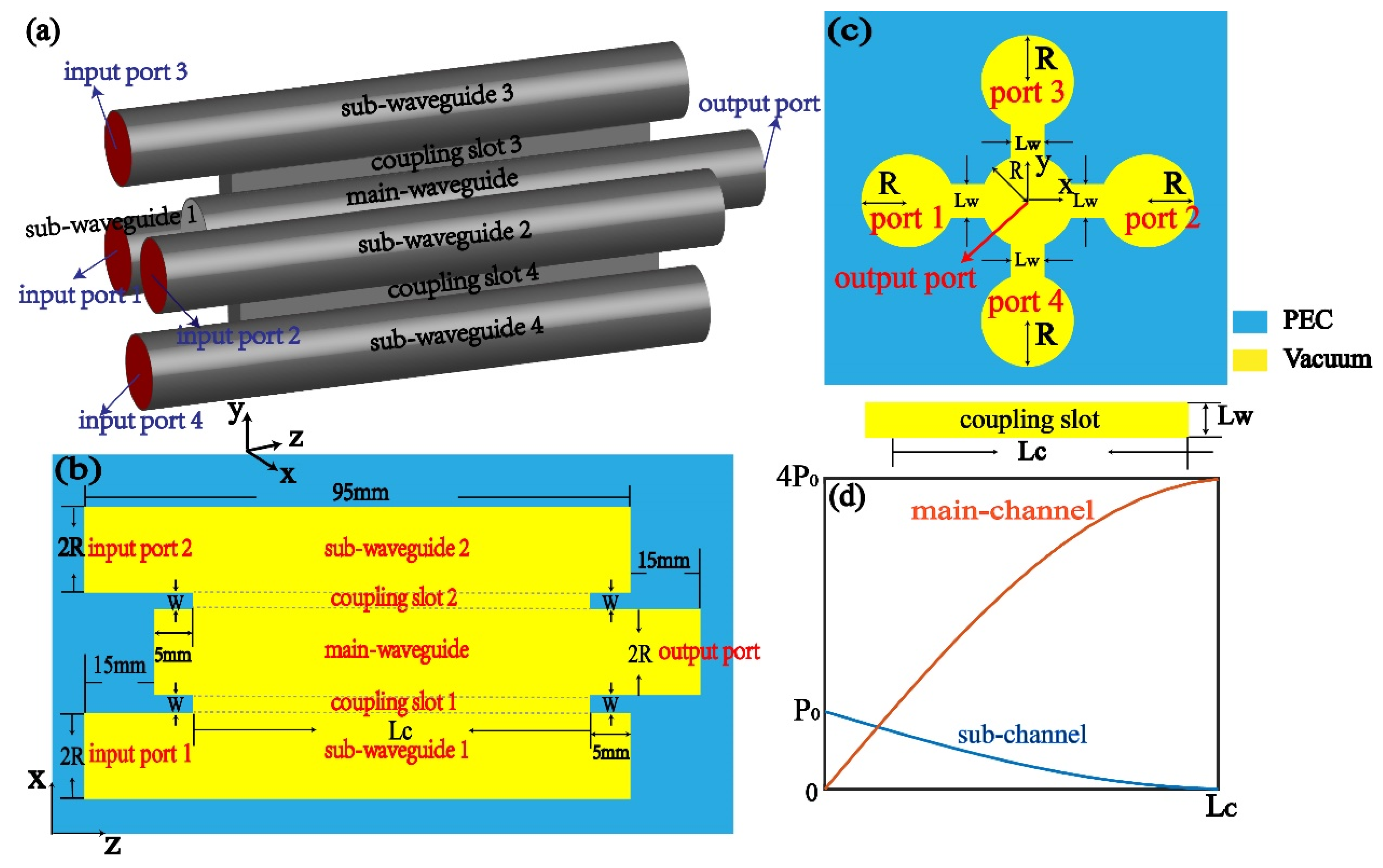
2.2. Model
3. Results
3.1. The Influence of the Coupling Length
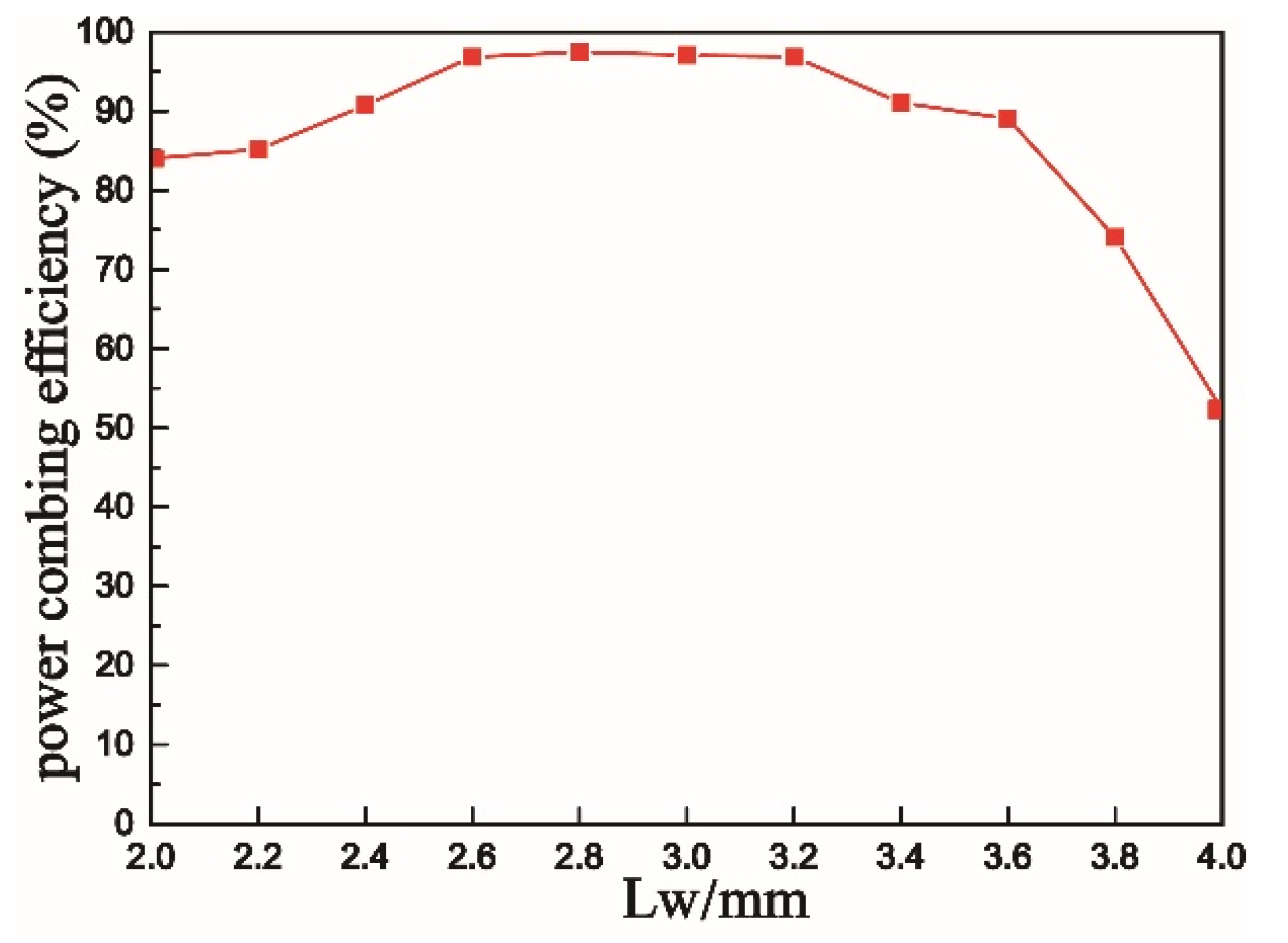
3.2. The Influence of the Coupling Length
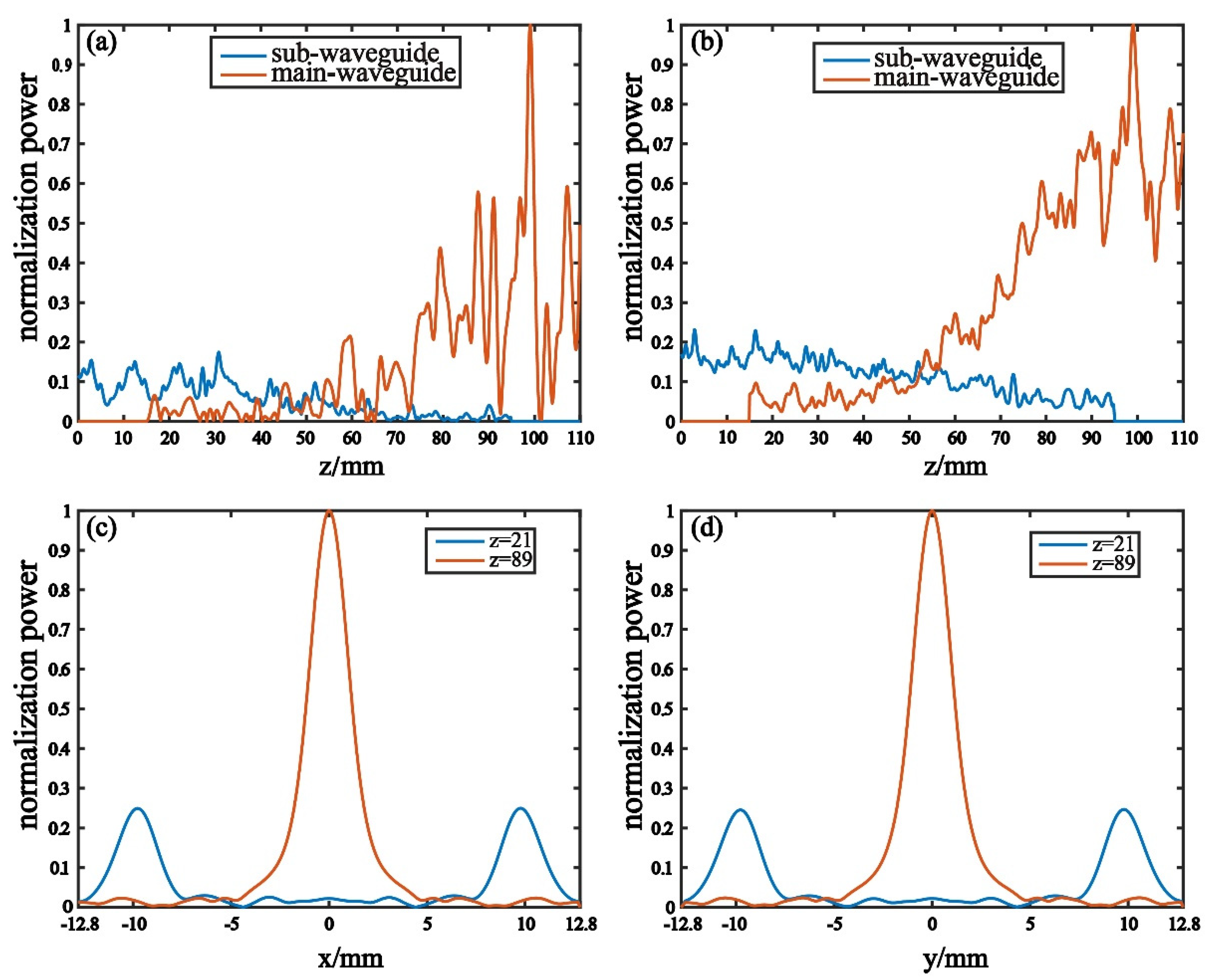
3.3. Stimulation Field
4. Discussion
5. Conclusions
Author Contributions
Funding
Acknowledgments
Conflicts of Interest
References
- Cao, X.; Tang, Z.; Wang, F. A two-way power amplifier based on waveguide spatial power-combing technique in Ka-band. Electromagnetics 2016, 36, 447–456. [Google Scholar] [CrossRef]
- Xiao, R.Z. Power combiner with high power capacity and high combination efficiency for two phase-locked relativistic backward wave oscillators. Appl. Phys. Lett. 2015, 107, 1–4. [Google Scholar] [CrossRef]
- Li, J.; Huang, W.; Zhu, Q.; Xiao, R.; Shao, H. Influence of a falling edge on high power microwave pulse combination. Phys. Plasmas 2016, 23, 073104. [Google Scholar] [CrossRef]
- Guo, L. A waveguide magic-T with coplanar arms for high-power solid-state power combing. IEEE Trans. Microw. Theory Technol. 2017, 65, 2942–2952. [Google Scholar] [CrossRef]
- Garcia-Perez, J.A.; Kosmopoulos, S.; Goussetis, G. A Compact 12-Way Slotted Waveguide Power Combiner for Ka-Band Applications. IEEE Microw. Wirel. Components Lett. 2017, 27, 135–137. [Google Scholar] [CrossRef]
- Seeds, A.J.; Williams, K.J. Microwave Photonics. J. Light. Technol. 2006, 24, 4628–4641. [Google Scholar] [CrossRef]
- Miller, S.E.; Tillotson, L.C. Optical and transmission research. Appl. Opt. 1966, 5, 1538–1549. [Google Scholar] [CrossRef] [PubMed]
- Lim, C.; Nirmalathas, A.; Bakaul, M.; Lee, K.-L.; Novak, D.; Waterhouse, R. Mitigation strategy for transmission impairments in millimeter-wave radio-over-fiber networks [Invited]. J. Opt. Netw. 2009, 8, 201–214. [Google Scholar] [CrossRef] [Green Version]
- Beas, J.; Castanon, G.; Aldaya, I.; Aragon-Zavala, A.; Campuzano, G. Millimeter-Wave Frequency Radio over Fiber Systems: A Survey. IEEE Commun. Surv. Tutor. 2013, 15, 1593–1619. [Google Scholar] [CrossRef]
- Yeom, S.; Lee, D.-S.; Son, J.-Y.; Jung, M.-K.; Jang, Y.; Jung, S.-W.; Lee, S.-J. Real-time outdoor concealed-object detection with passive millimeter wave imaging. Opt. Express 2011, 19, 2530–2536. [Google Scholar] [CrossRef]
- Fetterman, M.R.; Grata, J.; Jubic, G.; Kiser, W.L.; Visnansky, A. Simulation, acquisition and analysis of passive millimeter-wave images in remote sensing applications. Opt. Express 2008, 16, 20503. [Google Scholar] [CrossRef] [PubMed]
- Cui, C.; Kim, S.-K.; Song, R.; Song, J.-H.; Nam, S.; Kim, B.-S. A 77-GHz FMCW Radar System Using On-Chip Waveguide Feeders in 65-nm CMOS. IEEE Trans. Microw. Theory Tech. 2015, 63, 3736–3746. [Google Scholar] [CrossRef]
- Sarabandi, K.; Park, M. A radar cross-section model for power lines at millimeter-wave frequencies. IEEE Trans. Antennas Propag. 2003, 51, 2353–2360. [Google Scholar] [CrossRef] [Green Version]
- Song, K.; Fan, Y.; He, Z. Broadband Radial Waveguide Spatial Combiner. IEEE Microw. Wirel. Compon. Lett. 2008, 18, 73–75. [Google Scholar] [CrossRef]
- Zhang, F.; Song, K.; Fan, M.; Fan, Y. All-Metal-Waveguide Power Divider with High Power-Combining Efficiency. J. Infrared Millim. Terahertz Waves 2016, 37, 258–266. [Google Scholar] [CrossRef]
- Li, J.; Li, L.; Lü, L.; Shi, H.; Huo, H.; Zhang, A. Four-way waveguide power divider design for W-band applications. Int. J. RF Microw. Comput. Eng. 2018, 28, e21242. [Google Scholar] [CrossRef]
- Wei, T. Analysis and design of high-power and efficient, millimeter-wave power amplifier systems using zero degreecombiners. INT J. Electron 2018, 105, 1–11. [Google Scholar]
- Chang, K.; Sun, C. Millimeter-Wave Power-Combining Techniques. IEEE Trans. Microw. Theory Tech. 1983, 31, 91–107. [Google Scholar] [CrossRef]
- Takechi, O.; Shinohara, N.; Matsumoto, H. Spatial power combing oscillator array with band elimination filter connec-tion method for microwave power transmission. Electron. Commun. Jpn. 2005, 88, 1–9. [Google Scholar]
- Xie, Z.M.; Zhang, R. Gain factor of horn array feed offset parabolic cylindrical reflector antenna for spatial power combining. Microw. Opt. Technol. Lett. 2010, 52, 1742–1747. [Google Scholar] [CrossRef]
- Xie, X.; Zhao, X.; Liu, X. A waveguide-based spatial power combing module at higher millimeter-wave frequency. J. Infrared. Milli. Terahz. Waves 2013, 34, 299–307. [Google Scholar] [CrossRef]
- Franco, M.J. A high-performance dual-mode feed horn for parabolic reflectors with a stepped-septum polarizer in a circular wave-guide. IEEE Antennas Propag. Mag. 2011, 53, 142–146. [Google Scholar] [CrossRef]
- Lai, G.; Liang, R.; Zhang, Y.; Bian, Z.; Yi, L.; Zhan, G.; Zhao, R. Double plasmonic nanodisks design for electromagnetically induced transparency and slow light. Opt. Express 2015, 23, 6554–6561. [Google Scholar] [CrossRef] [PubMed]
- Huang, Y.; Min, C.; Veronis, G. Broadband near total light absorption in non-PT-symmetric waveguide-cavity systems. Opt. Express 2016, 24, 22219–22231. [Google Scholar] [CrossRef] [Green Version]
- Elfrgani, A.; Seidfaraji, H.; Yurt, S.C.; Fuks, M.I.; Schamiloglu, E. Power Combiner for High Power Cerenkov Devices. IEEE Trans. Plasma Sci. 2016, 44, 2268–2271. [Google Scholar] [CrossRef]
- Xiao, R.; Deng, Y.; Song, Z.; Li, J.; Sun, J.; Chen, C. An All Circular Waveguide Four-Way Power Combiner With Ultrahigh-Power Capacity and High Combination Efficiency. IEEE Trans. Plasma Sci. 2018, 46, 1–5. [Google Scholar] [CrossRef]
- Fang, J.Y. An X band synthesizer for a few hundred megawatt level power microwaves. Acta Phys. Sin. 2011, 60, 088402-1–088402-7. [Google Scholar]


Publisher’s Note: MDPI stays neutral with regard to jurisdictional claims in published maps and institutional affiliations. |
© 2021 by the authors. Licensee MDPI, Basel, Switzerland. This article is an open access article distributed under the terms and conditions of the Creative Commons Attribution (CC BY) license (https://creativecommons.org/licenses/by/4.0/).
Share and Cite
Tu, S.; Liu, J.; Wang, T.; Yang, Z.; Wang, K. Design of a 94 GHz Millimeter-Wave Four-Way Power Combiner Based on Circular Waveguide Structure. Electronics 2021, 10, 1795. https://doi.org/10.3390/electronics10151795
Tu S, Liu J, Wang T, Yang Z, Wang K. Design of a 94 GHz Millimeter-Wave Four-Way Power Combiner Based on Circular Waveguide Structure. Electronics. 2021; 10(15):1795. https://doi.org/10.3390/electronics10151795
Chicago/Turabian StyleTu, Siyu, Jinsong Liu, Tianyi Wang, Zhengang Yang, and Kejia Wang. 2021. "Design of a 94 GHz Millimeter-Wave Four-Way Power Combiner Based on Circular Waveguide Structure" Electronics 10, no. 15: 1795. https://doi.org/10.3390/electronics10151795