
Multi-Objective Optimization of a Battery-Supercapacitor Hybrid Energy Storage System Based on the Concept of Cyber-Physical System

 ,
,
Abstract
:1. Introduction
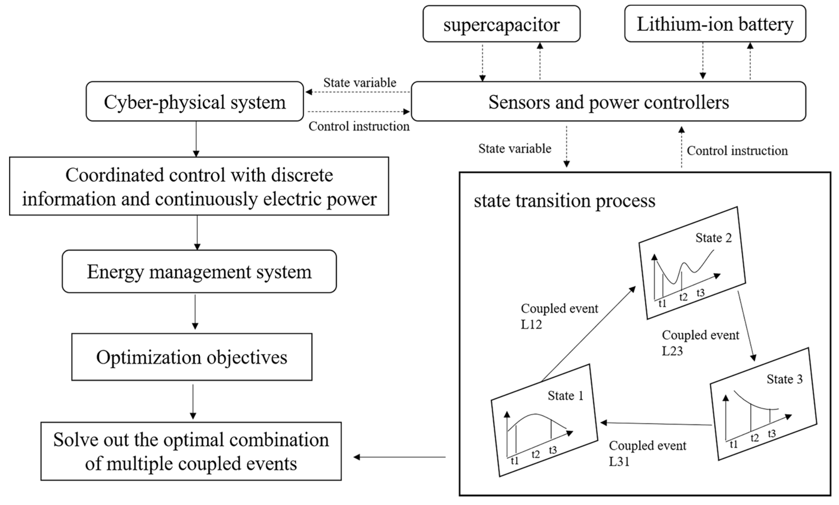
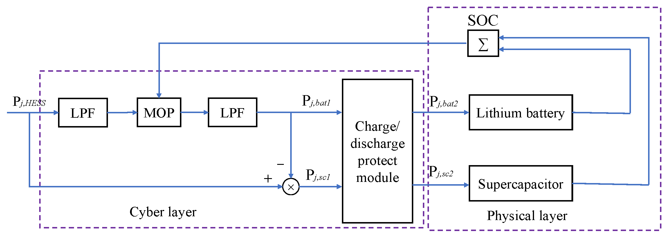
2. System Design for Integrating CPS into HESS
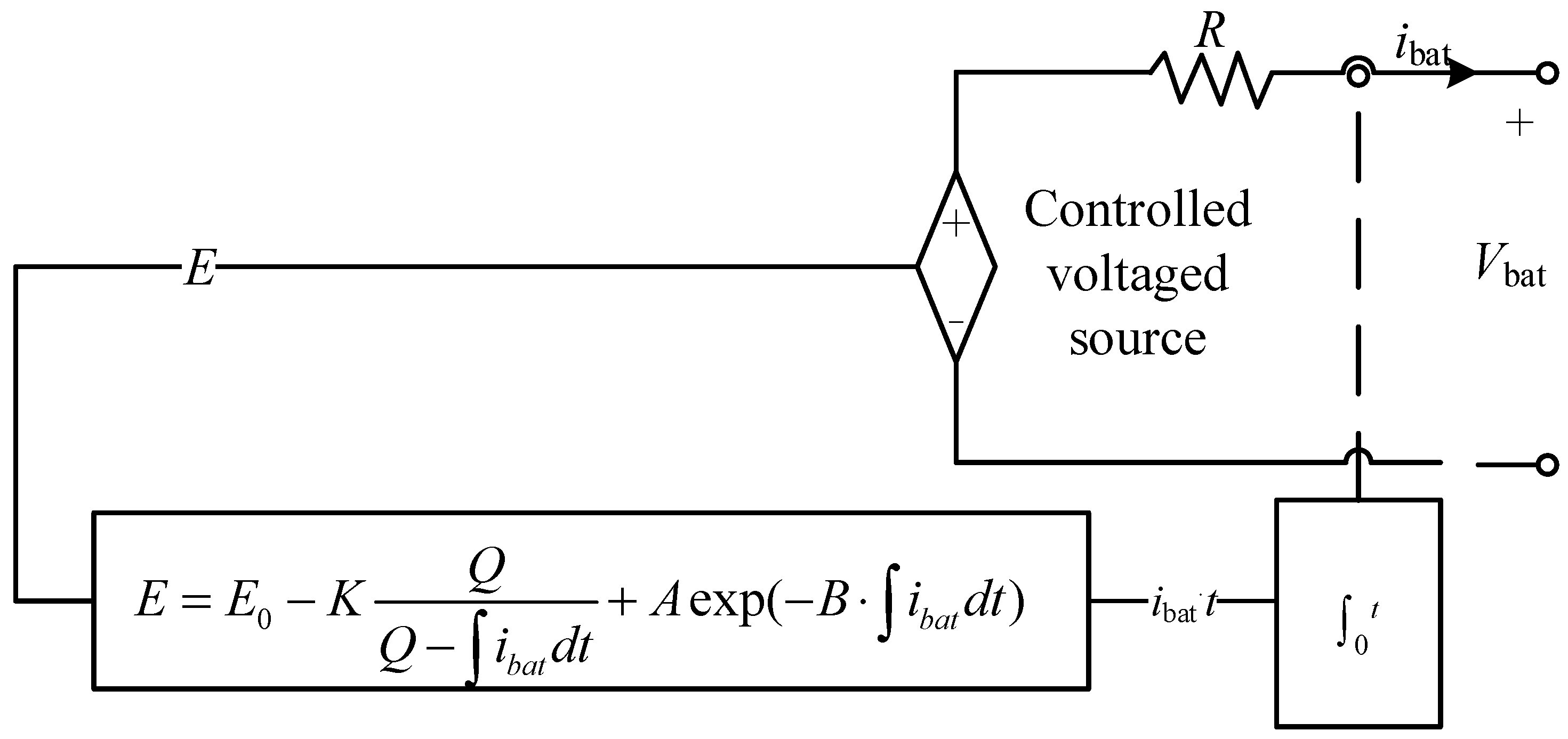
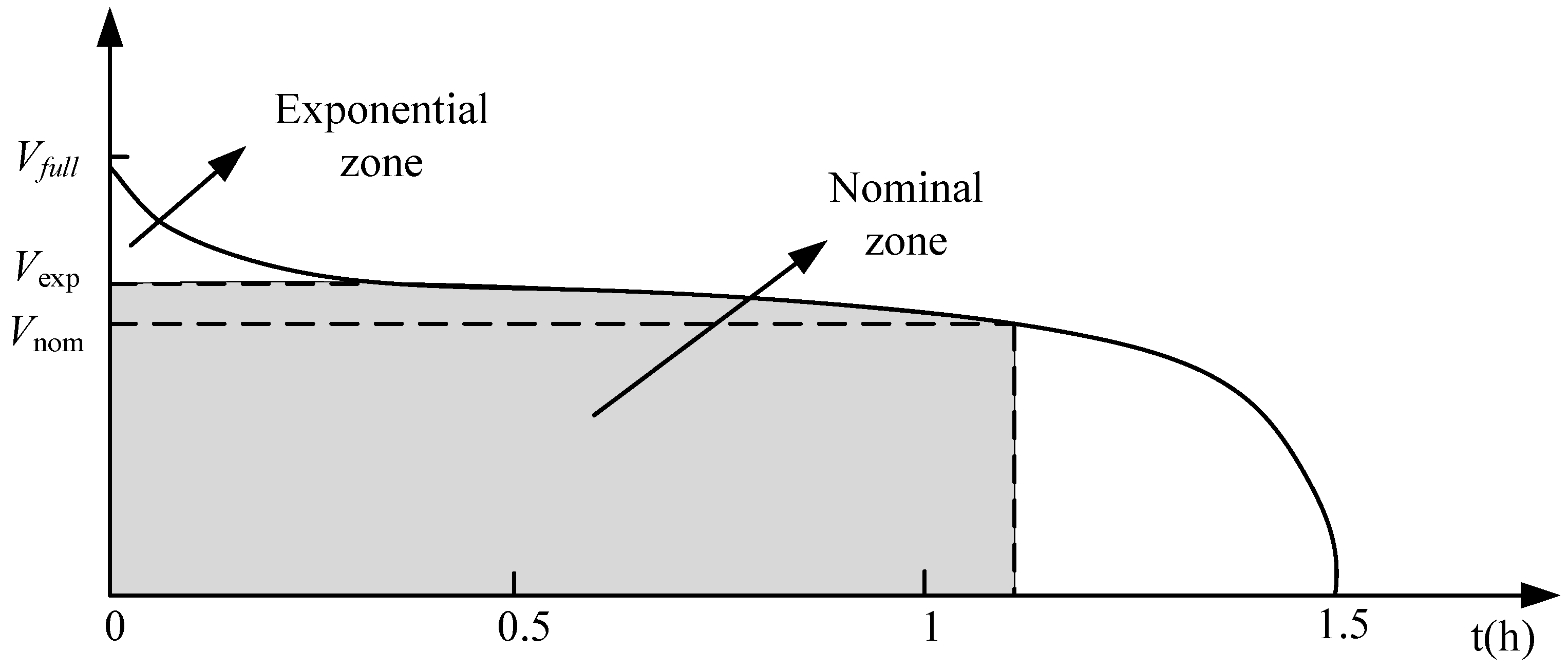
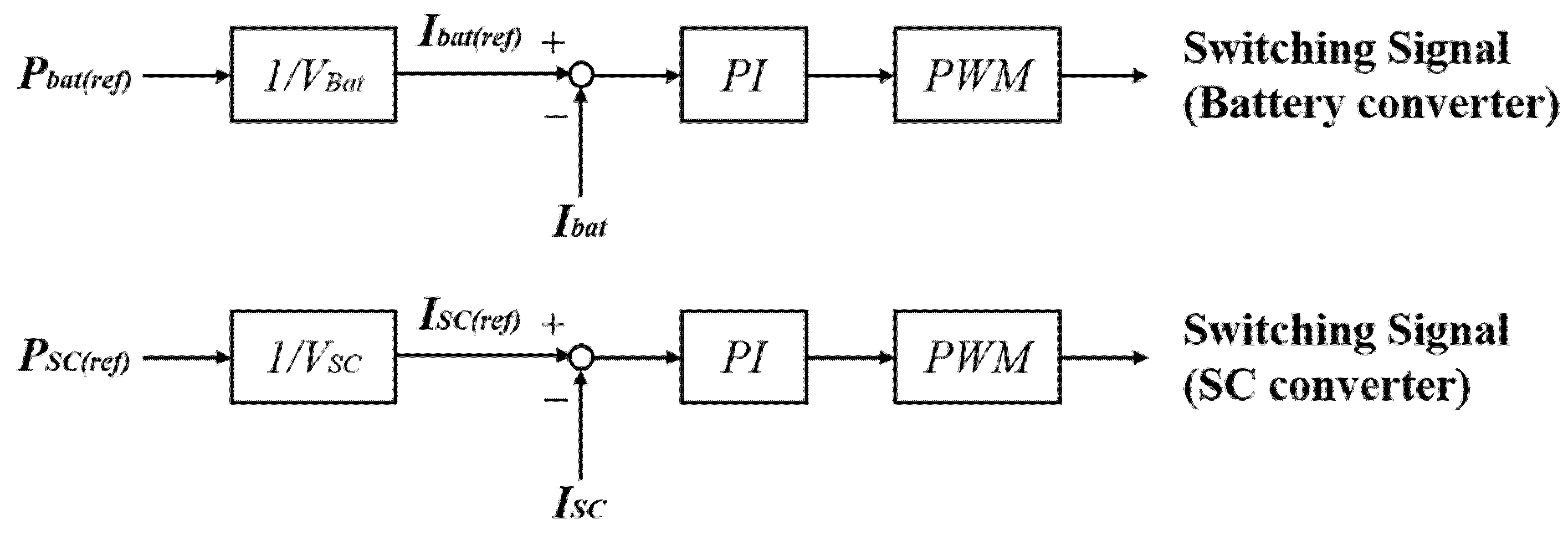
2.1. Physical Layer
2.2. Cyber Layer
2.2.1. Low-Pass Filtering Algorithm
2.2.2. Multi-Objective Optimization Model
- (a)
- Loss model
- (b)
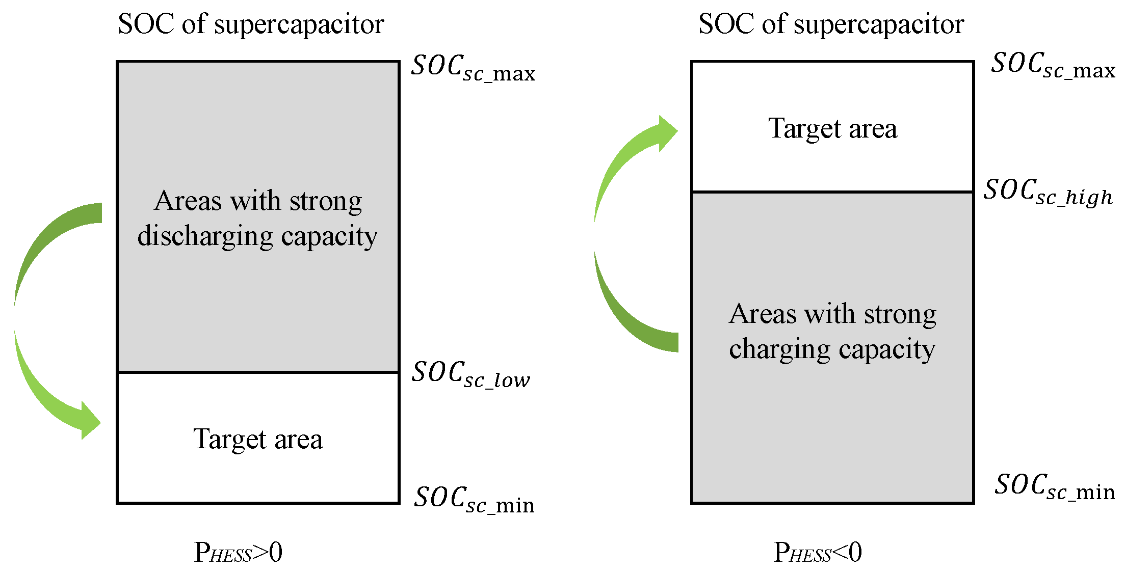
- Optimization model of supercapacitor utilization
- (c)
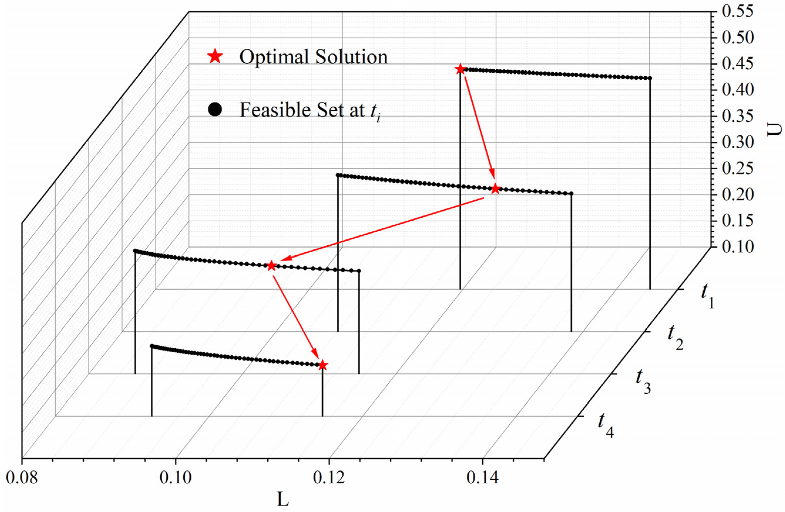
- Integration of multi-objective optimization model
- (d)
- Charge/discharge protect model
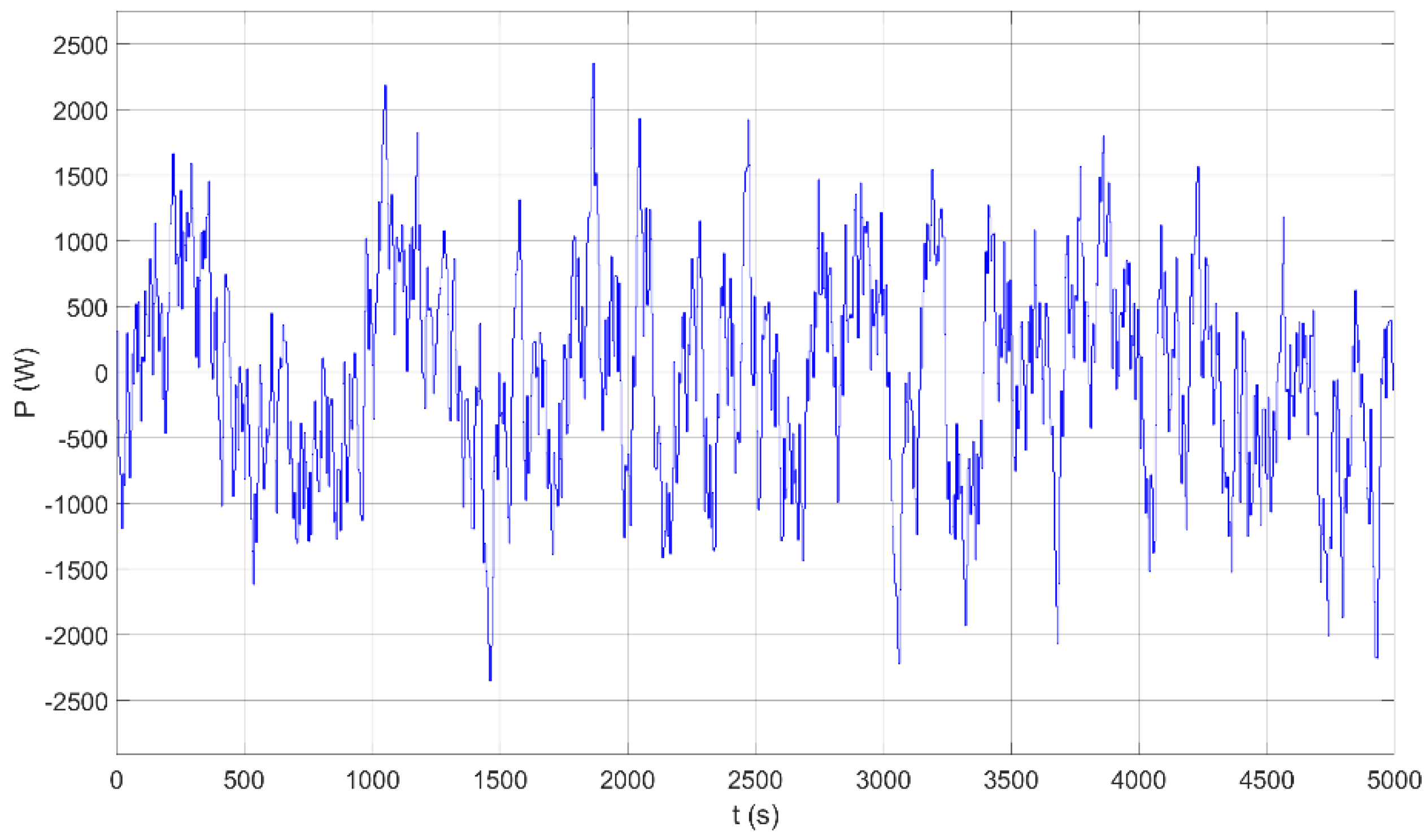
3. Simulation Results
4. Rain-Flow Counting Algorithm for Battery Lifetime Prediction
5. Case Study
6. Conclusions
Author Contributions
Funding
Acknowledgments
Conflicts of Interest
References
- Goel, S.; Sharma, R. Performance evaluation of stand alone, grid connected and hybrid renewable energy systems for rural application: A comparative review. Renew. Sustain. Energy Rev. 2017, 78, 1378–1389. [Google Scholar] [CrossRef]
- Li, J.; Xiong, R.; Yang, Q.; Liang, F.; Zhang, M.; Yuan, W. Design/test of a hybrid energy storage system for primary frequency control using a dynamic droop method in an isolated microgrid power system. Appl. Energy 2017, 201, 257–269. [Google Scholar] [CrossRef]
- Yan, J.; Zhai, Y.; Wijayatunga, P.; Mohamed, A.M.; Campana, P.E. Renewable energy integration with mini/micro-grids. Appl. Energy 2017, 201, 241–244. [Google Scholar] [CrossRef]
- Upadhyay, S.; Sharma, M.P. A review on configurations, control and sizing methodologies of hybrid energy systems. Renew. Sustain. Energy Rev. 2014, 38, 47–63. [Google Scholar] [CrossRef]
- Lujano-Rojas, J.M.; Dufo-López, R.; Atencio-Guerra, J.L.; Rodrigues, E.M.G.; Bernal Agustín, J.L.; Catalão, J.P.S. Operating conditions of lead-acid batteries in the optimization of hybrid energy systems and microgrids. Appl. Energy 2016, 179, 590–600. [Google Scholar] [CrossRef]
- Linssen, J.; Stenzel, P.; Fleer, J. Techno-economic analysis of photovoltaic battery systems and the influence of different consumer load profiles. Appl. Energy 2017, 185, 2019–2025. [Google Scholar] [CrossRef]
- Abeywardana, D.B.W.; Hredzak, B.; Agelidis, V.G. A fixed-frequency sliding mode controller for a boost-inverter-based battery-supercapacitor hybrid energy storage system. IEEE Trans. Power Electron. 2017, 32, 668–680. [Google Scholar] [CrossRef]
- Wang, X.; Yu, D.; Blond, S.L.; Zhao, Z.; Wilson, P. A novel controller of a battery-supercapacitor hybrid energy storage system for domestic applications. Energy Build. 2017, 141, 167–174. [Google Scholar] [CrossRef] [Green Version]
- Palizban, O.; Kauhaniemi, K. Energy storage systems in modern grids-Matrix of technologies and applications. J. Energy Storage 2016, 3, 248–259. [Google Scholar] [CrossRef]
- Wu, T.; Shi, X.; Liao, L.; Zhou, C.; Zhou, H.; Su, Y. A Capacity Configuration Control Strategy to Alleviate Power Fluctuation of Hybrid Energy Storage System Based on Improved Particle Swarm Optimization. Energies 2019, 12, 642. [Google Scholar] [CrossRef] [Green Version]
- Jing, W.; Lai, C.H.; Wong, W.S.H.; Wong, M.L.D. A comprehensive study of battery-supercapacitor hybrid energy storage system for standalone PV power system in rural electrification. Appl. Energy 2018, 224, 340–356. [Google Scholar] [CrossRef]
- Li, J.; Wang, X.; Zhang, Z.; Blond, S.L.; Yang, Q.; Zhang, M.; Yuan, W. Analysis of a new design of the hybrid energy storage system used in the residential m-CHP systems. Appl. Energy 2017, 187, 169–179. [Google Scholar] [CrossRef] [Green Version]
- Ni, F.; Yan, L.; Liu, J.; Shi, M.; Zhou, J.; Chen, X. Fuzzy logic based virtual capacitor adaptive control for multiple HESSs in a DC microgrid system. Int. J. Electr. Power Energy Syst. 2019, 107, 78–88. [Google Scholar] [CrossRef]
- Wu, J.; Wei, Z.; Li, W.; Wang, Y.; Li, Y.; Sauer, D.U. Battery Thermal- and Health-Constrained Energy Management for Hybrid Electric BusBased on Soft Actor-Critic DRL Algorithm. IEEE Trans. Ind. Inf. 2021, 17, 3751–3761. [Google Scholar] [CrossRef]
- Wu, J.; Wei, Z.; Liu, K.; Quan, Z.; Li, Y. Battery-involved energy management for hybrid electric bus based on expert-assistance deep deterministic policy gradient algorithm. IEEE Trans. Veh. Technol. 2020, 69, 12786–12796. [Google Scholar] [CrossRef]
- Abdelkader, A.; Rabeh, A.; Ali, D.M.; Mohamed, J. Multi-objective genetic algorithm based sizing optimization of a stand-alone wind/PV power supply system with enhanced battery/supercapacitor hybrid energy storage. Energy 2018, 163, 351–363. [Google Scholar] [CrossRef]
- Amara, S.; Toumi, S.; Salah, C.B.; Saidi, A.S. Improvement of techno-economic optimal sizing of a hybrid off-grid micro-grid system. Energy 2021, 233, 121166. [Google Scholar] [CrossRef]
- Fantauzzi, M.; Lauria, F.; Scalfati, A. Sizing energy storage systems in DC networks: A general methodology based upon power lossed minimization. Appl. Energy 2017, 187, 862–872. [Google Scholar] [CrossRef]
- Song, Z.; Li, J.; Han, X.; Xu, L.; Lu, L.; Ouyang, M.; Hofmann, H. Multi-objective optimization of a semi-active battery/supercapacitor energy system for electric vehicles. Appl. Energy 2014, 135, 212–224. [Google Scholar] [CrossRef]
- Choi, M.; Kim, S.; Seo, S. Energy management optimization in a battery/supercapacitor hybrid energy storage system. IEEE Trans. Smart Grid 2013, 3, 463–472. [Google Scholar] [CrossRef]
- Wei, Z.; Zhao, J.; Ji, D.; Tseng, K.J. A multi-timescale estimator for battery state of charge and capacity dual estimation based on an online identified model. Appl. Energy 2017, 204, 1264–1274. [Google Scholar] [CrossRef]
- Wang, H.; Huang, Y.; Khajepour, A. Cyber-Physical Control for Energy Management of Off-Road Vehicles with Hybrid Energy Storage Systems. IEEE Trans. Mechatr. 2018, 23, 2609–2618. [Google Scholar] [CrossRef]
- Wang, Y.; Nguyen, T.L.; Xu, Y.; Shi, D. Distributed control of heterogeneous energy storage systems in islanded microgrids: Finite-time approach and cyber-physical implementation. Electr. Power Energy Syst. 2020, 119, 105898. [Google Scholar] [CrossRef]
- Wang, Y.; Nguyen, T.L.; Xu, Y.; Li, Z.; Tran, Q.; Caire, R. Cyber-Physical Design and Implementation of Distributed Event-Triggered Secondary Control in Islanded Microgrids. IEEE Trans. Ind. Appl. 2019, 55, 5631–5642. [Google Scholar] [CrossRef]
- Cabrane, Z.; Ouassaid, M.; Maaroufi, M. Battery and supercapacitor for photovoltaic energy storage: A fuzzy logic management. IET Renew. Power Gener. 2017, 11, 1157–1165. [Google Scholar] [CrossRef]
- Tremblay, O.; Dessaint, L.A.; Dekkiche, A.I. A generic battery model for the dynamic simulation of hybrid electric vehicles. In Proceedings of the 2007 IEEE Vehicle Power and Propulsion Conference, Arlington, TX, USA, 9–12 September 2007. [Google Scholar]
- Xin, S.; Guo, Q.; Sun, H.; Zhang, B.; Wang, J.; Chen, C. Cyber-physical modeling and cyber-contingency assessment of hierarchical control systems. IEEE Trans. Smart Grid 2017, 6, 2375–2385. [Google Scholar] [CrossRef]
- Liu, R.; Vellaithurai, C.; Biswas, S.S.; Gamage, T.T.; Srivastava, A.K. Analyzing the cyber-physical impact of cyber events on the power grid. IEEE Trans. Smart Grid 2015, 6, 2444–2453. [Google Scholar] [CrossRef]
- Huang, C.; Wang, D.; Chawla, N.V. Scalable uncertainty-aware truth discovery in big data social sensing applications for cyber-physical systems. IEEE Trans. Big Data 2020, 6, 702–713. [Google Scholar] [CrossRef] [Green Version]
- Ramesh, M.V.; Devidas, A.R.; Athira, K.; Rangan, V. Using CPS enabled microgrid System for optimal power utilization and supply strategy. Energy Build. 2017, 145, 32–43. [Google Scholar] [CrossRef]
- Lou, S.; Feng, Y.; Li, Z.; Gao, Y.; Tan, J. An edge-based distributed decision -making method for product design scheme evaluation. IEEE Trans. Ind. Inf. 2021, 17, 1375–1385. [Google Scholar] [CrossRef]
- Jing, W.; Lai, C.H.; Wong, S.H.W.; Wong, M.L.D. Battery-supercapacitor hybrid energy storage system in standalone DC microgrids: A review. IET Renew. Power Gener. 2017, 11, 461–469. [Google Scholar] [CrossRef]
- Ise, T.; Kita, M.; Taguchi, A. A hybrid energy storage with a SMES and secondary battery. IEEE Trans. Appl. Supercond. 2005, 15, 1915–1918. [Google Scholar] [CrossRef]
- Castaings, A.; Lhomme, W.; Trigui, R.; Bouscayrol, A. Comparison of energy management strategies of a battery/supercapacitors system for electric vehicle under real-time constraints. Appl. Energy 2016, 163, 190–200. [Google Scholar] [CrossRef]
- Jia, H.; Mu, Y.; Qi, Y. A statistical model to determine the capacity of battery–supercapacitor hybrid energy storage system in autonomous microgrid. Electr. Power Energy Syst. 2014, 54, 516–524. [Google Scholar] [CrossRef]
- Carpinteri, A.; Fortese, G.; Ronchei, C.; Scorza, D.; Spagnoli, A.; Vantadori, S. Fatigue life evaluation of metallic structures under multiaxial random loading. Int. J. Fatigue 2016, 90, 191–199. [Google Scholar] [CrossRef]
- Li, J.; Gee, A.M.; Zhang, M.; Yuan, W. Analysis of battery lifetime extension in a SMES-battery hybrid energy storage system using a novel battery lifetime model. Energy 2015, 86, 175–185. [Google Scholar] [CrossRef] [Green Version]
- Niu, Y.; Santoso, S. Sizing and coordinating fast and slow response energy storage systems to mitigate hourly wind power variations. IEEE Trans. Smart Grid 2018, 9, 1107–1117. [Google Scholar] [CrossRef]
- Li, J.; Yang, Q.; Robinson, F.; Liang, F.; Zhang, M.; Yuan, W. Design and test of a new droop control algorithm for a SMES/battery hybrid energy storage system. Energy 2017, 118, 1110–1122. [Google Scholar] [CrossRef]


| Parameter Name | Parameter Symbol | Parameter Values |
|---|---|---|
| Rated capacity of LiB | Qbt | 10 Ah |
| Battery nominal voltage | Vbt | 90–110 V |
| Battery internal resistance | Rbt | 0.5 Ω |
| Rated capacity of supercapacitor | Csc | 20 F |
| Supercapacitor nominal voltage | Vsc | 40–100 V |
| Supercapacitor internal resistance | Rsc | 50 mΩ |
| Inductance resistance | RL1, RL2 | 0.2 Ω |
| Switch on resistance | Rs1~Rs4 | 0.1 Ω |
| Low-pass filtering time constant | Tf | 30 s |
| Sampling period | Tsam | 5 s |
| Switching frequency | fs | 20 kHz |
| Switch current rising time | tr | 0.5 μs |
| Switch current falling time | tf | 0.5 μs |
| Battery maximum current | ibatmax | 30 A |
| Supercapacitor maximum current | iscmax | 50 A |
| Multi-objective optimization weight coefficient | λ | 0.5 |
| The resistance of the copper rate | ρ | 1.75*10−8 Ω·m |
| Sectional area | S | 2.5 mm2 |
| Wire length | L | 10 m |
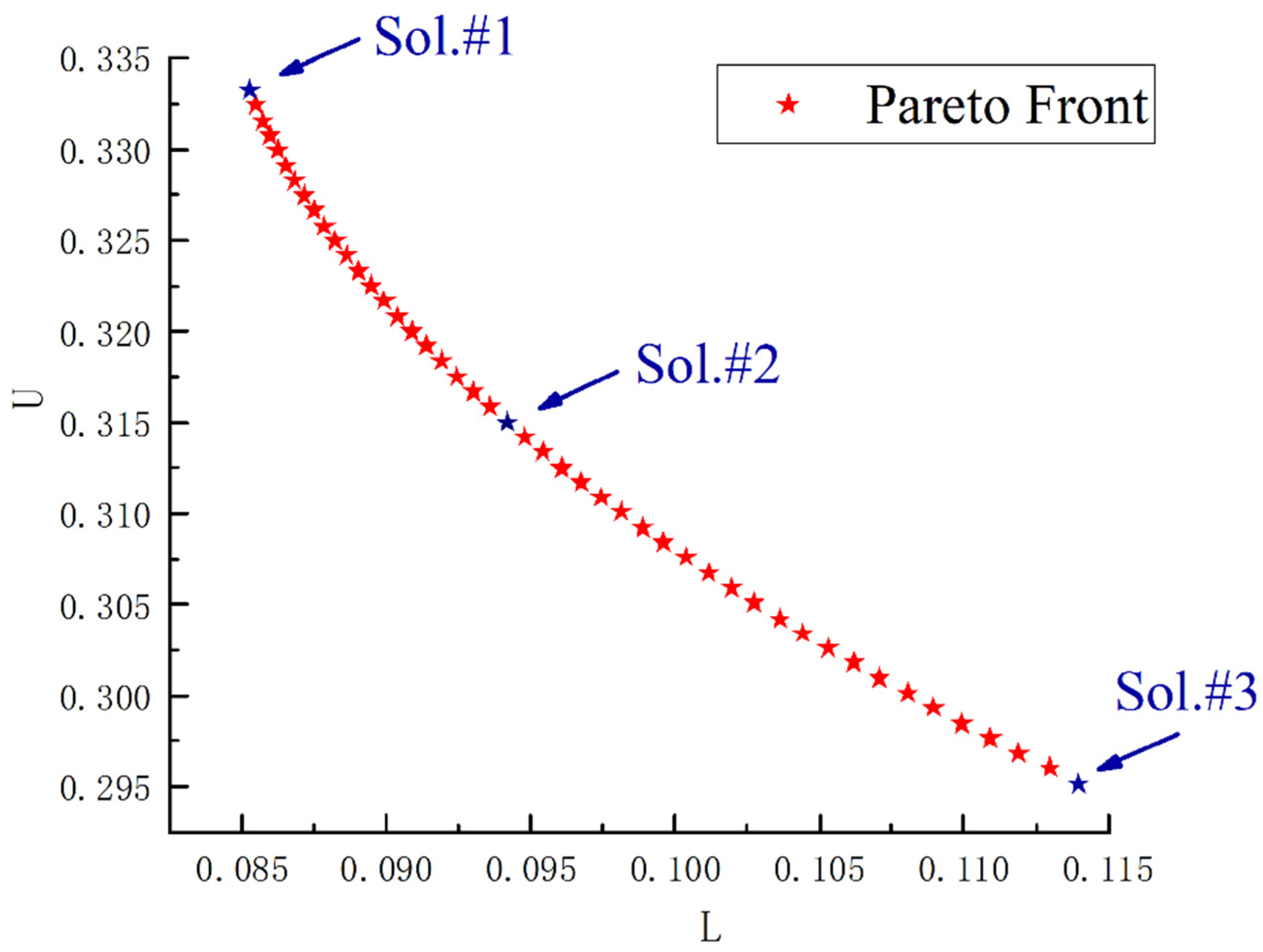
| Solution | L | U | Energy Loss(W) | Utilization Rate of the Supercapacitor |
|---|---|---|---|---|
| #1 | 0.085 | 0.334 | 60.25 | 69.12% |
| #2 | 0.093 | 0.316 | 62.75 | 71.24% |
| #3 | 0.114 | 0.295 | 74.02 | 72.31% |
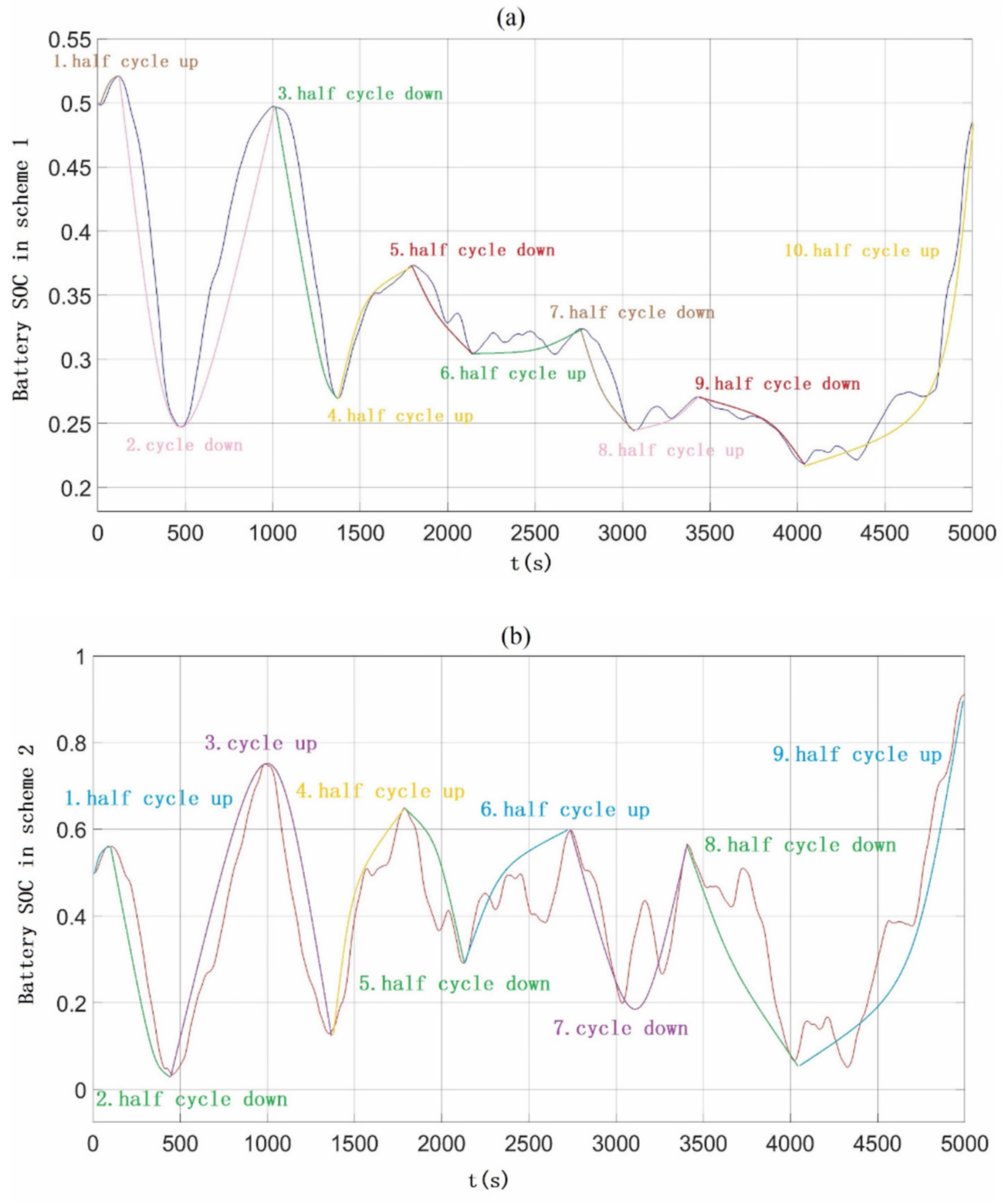
| Scenarios | Peak to Peak Current | Prediction of Battery Lifetime |
|---|---|---|
| Scheme 1 | 9.1A | 10.20 years |
| Scheme 2 | 27.9A | 3.51 years |
| Parameter Name | Parameter Symbol | Parameter Values |
|---|---|---|
| Rated capacity of LiB | Qbt | 1000 Ah |
| Battery nominal voltage | Vbt | 90–110 V |
| Battery internal resistance | Rbt | 0.5 Ω |
| Rated capacity of supercapacitor | Csc | 1000 F |
| Supercapacitor nominal voltage | Vsc | 40–100 V |
| Supercapacitor internal resistance | Rsc | 50 mΩ |
| Inductance resistance | RL1, RL2 | 0.2 Ω |
| Switch on resistance | Rs1~Rs4 | 0.1 Ω |
| Low-pass filtering time constant | Tf | 30 s |
| Sampling period | Tsam | 30 s |
| Switching frequency | fs | 20 kHz |
| Switch current rising time | tr | 0.5 μs |
| Switch current falling time | tf | 0.5 μs |
| Battery maximum current | ibatmax | 30 A |
| Supercapacitor maximum current | iscmax | 50 A |
| Multi-objective optimization weight coefficient | λ | 0.5 |
| The resistance of the copper rate | ρ | 1.75 × 10⁻⁸ Ω·m |
| Sectional area | S | 2.5 mm2 |
| Wire length | L | 10 m |
Publisher’s Note: MDPI stays neutral with regard to jurisdictional claims in published maps and institutional affiliations. |
© 2021 by the authors. Licensee MDPI, Basel, Switzerland. This article is an open access article distributed under the terms and conditions of the Creative Commons Attribution (CC BY) license (https://creativecommons.org/licenses/by/4.0/).
Share and Cite
Pan, C.; Tao, S.; Fan, H.; Shu, M.; Zhang, Y.; Sun, Y. Multi-Objective Optimization of a Battery-Supercapacitor Hybrid Energy Storage System Based on the Concept of Cyber-Physical System. Electronics 2021, 10, 1801. https://doi.org/10.3390/electronics10151801
Pan C, Tao S, Fan H, Shu M, Zhang Y, Sun Y. Multi-Objective Optimization of a Battery-Supercapacitor Hybrid Energy Storage System Based on the Concept of Cyber-Physical System. Electronics. 2021; 10(15):1801. https://doi.org/10.3390/electronics10151801
Chicago/Turabian StylePan, Chenyun, Shengyu Tao, Hongtao Fan, Mengyao Shu, Yong Zhang, and Yaojie Sun. 2021. "Multi-Objective Optimization of a Battery-Supercapacitor Hybrid Energy Storage System Based on the Concept of Cyber-Physical System" Electronics 10, no. 15: 1801. https://doi.org/10.3390/electronics10151801