Abstract
Presently, the technology development trend of active noise control (ANC) systems is focused on implementing advanced adaptive filters in resource-constrained electronic appliances. Recently, several authors have proved that the use of two adaptive filter algorithms significantly improves the overall adaptive filter performance. However, the computational cost of these approaches is significantly increased since they use two filters simultaneously. Consequently, these filters cannot be implemented in these devices. To solve this problem, we propose a new ANC structure with switching selection based on filtered-x normalized least mean square (FxNLMS) and filtered-x sign least mean square (FxSLMS) algorithms to reduce the computational cost of the ANC system. The improvement of this factor has allowed us to introduce for the first time an advanced spike-based architecture, which can perform dual filter operations using dynamic routing, to be used in real ANC applications. The results have demonstrated that the computational cost of the proposed dual D-FxNLMS/SLMS algorithm is lower compared with previously reported solutions.
1. Introduction
In recent years, active noise systems (ANC) have been widely used in practical applications, such as car cabins [1,2], washing machines [3], railway train systems [4], headphones [5], infant incubators [6], motorcycle helmets [7], open windows [8], diesel generators [9], hearing aids [10], earmuff systems [11], power transformers [12], acoustic ducts [13], and traffic noise reduction [14], among others. Recently, the trend of the electronics market demands the design of portable devices in which the area is limited. Hence, the implementation of ANC systems in resource-constrained electronic appliances becomes a big challenge. In addition, these ANC systems must exhibit good convergence properties to reduce the noise efficiently. To date, several authors have proposed potential solutions based on convex combinations to efficiently reduce the noise [15,16]. For example, Ferrer et al. [17] presented a convex combination structure applied to single-channel and multichannel active noise control systems. Other approach, which was applied to nonlinear ANC systems, was presented by George et al. [18]. This system is composed of a functional link artificial neural network (FLANN) and a Volterra filter. Al Omour et al. [19] proposed the Filtered-x LMF (FxLMF) and Leaky FxLMF (LFxLMF) algorithms. The authors exploited the best features of each algorithm to create an advanced convex combination ANC structure. On the other hand, Song et al. [20] presented a convex filtered-x generalized mixed norm (C-FxGMN) algorithm with the aim of improving the algorithm performance in terms of convergence speed and noise reduction level. Song et al. [21] presented a convex filtered-x least mean square/fourth (C-FxLMS/F) algorithm to improve the convergence properties. Recently, Vazquez et al. [22] presented single-channel and multichannel ANC systems based on the filtered-x affine projection-like (FxAPL-I) and filtered-x least mean square (FxLMS) algorithms with filter selection strategy. In general, these existing approaches intended to improve the convergence properties at the cost of increasing their computational cost. This factor is vital when the implementation of these algorithms in embedded devices, such as field-programmable gate array (FPGA), digital signal processor (DSP), multicore processors and graphics processing unit (GPU) are required. As a consequence, very few works have dedicated efforts to implement these approaches in embedded devices since their implementation demands a large area consumption and a high computational performance. For example, Gonzalez et al. [23] presented the implementation of the convex-combined modified filtered-x adaptive algorithm in a multicore processor. This system exhibits high convergence speed and low mean square error (MSE) by paying a high penalty in terms of computational cost. Recently, Felix et al. [24] presented the implementation of a modified filtered-x least mean square/fourth (MC-FxLMS/F) algorithm in a FPGA to reduce the noise generated by industrial fans. However, the area consumption and processing speed are not reported. Despite having significant achievements in the development of adaptive filtering schemes based on convex combination, there are still great challenges in the implementation of these systems in resource-constrained devices since they are currently highly demanded in consumer electronic devices. In this work, we present a new ANC structure with switching selection using the proposed D-FxNLMS/SLMS algorithm. In addition, we present a new hardware architecture capable of simulating the dual adaptive filter at high processing speeds. Here, we use dynamic routing, to save a large area consumption by simulating two adaptive filters virtually. Moreover, we develop a versatile graphical user interface to configure the adaptive filter’s parameters in the spike-based hardware architecture and to monitor the error signal, which represents the noise reduction level, in real-time.
2. Proposed D-FxNLMS/SLMS Algorithm
In general, the filtered-x ANC structure is mainly composed of a primary path, , an secondary path, , an estimation of the secondary path, , and an adaptive filter, , as shown in Figure 1.
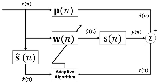
Figure 1.
General scheme of the filtered-x ANC structure.
The filtering signal process starts when the reference signal is filtered by the estimation of the secondary path, to generate . This process can be described as follows:
where represents a FIR filter of length, M, and contains the samples of the reference signal . Equation (2) indicates the process to generate the adaptive filter output .
where has the length N and the reference signal vector is given by . Once the adaptive filter output is obtained, it propagates via secondary path, , to obtain the signal, . On the other hand, the reference signal, , is acoustically propagated through the primary path, , to be transformed to . To update the FIR filter coefficients of the adaptive filter, the error signal, , must be obtained by subtracting signals and .
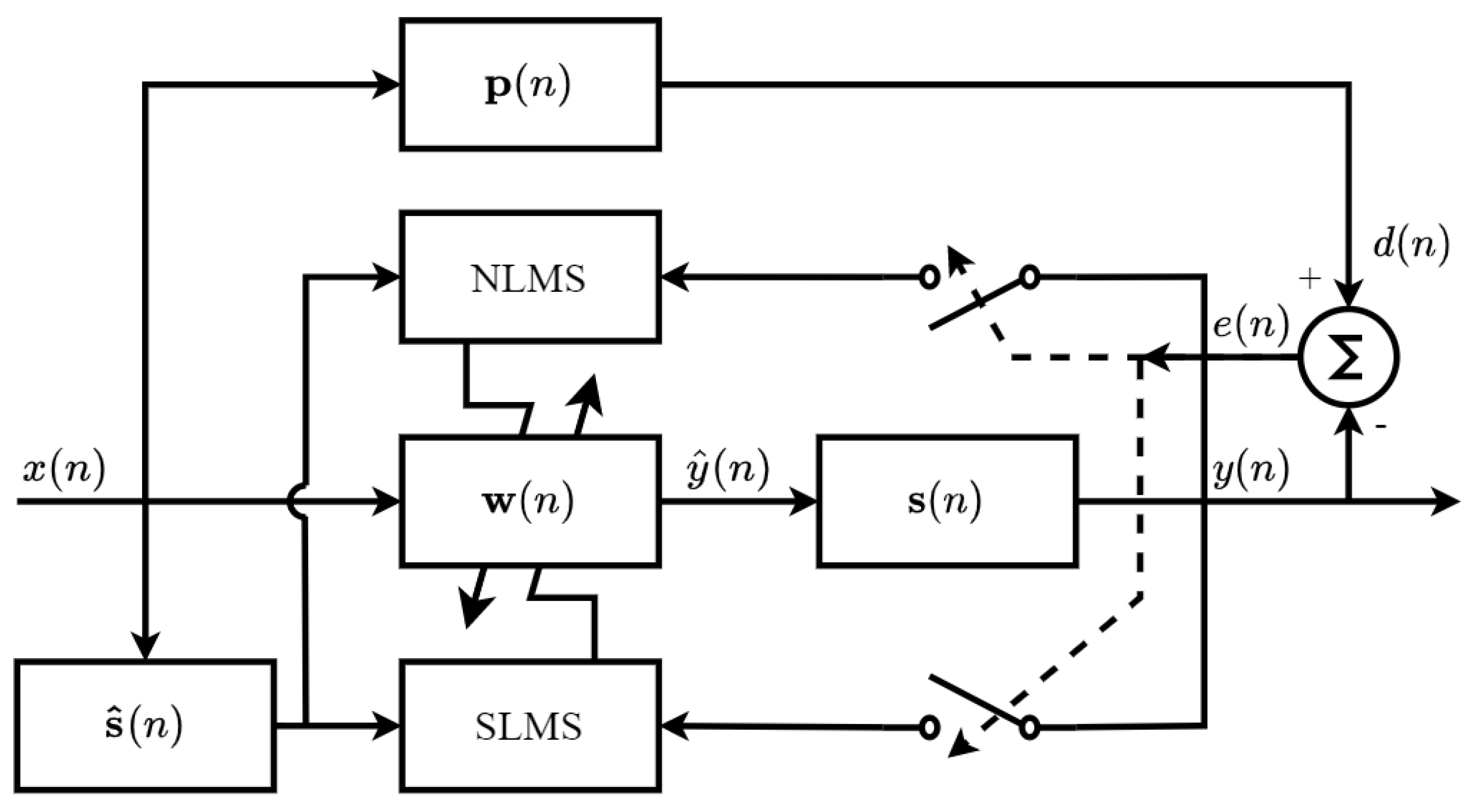
Commonly, the filtered-x ANC structure uses a single adaptive filter to generate a control signal. However, a well-known trade-off is established between convergence properties and computational cost. Recently, several authors have shown that the fusion of two adaptive filters with complementary features significantly improves the convergence properties of the filter in comparison when a single filter is employed. In general, this fusion uses a high-convergence-speed adaptive filter and a high-precision adaptive filter. However, the use of two filters significantly increases the computational cost of the ANC system. Hence, there is still a big challenge to create an ANC structure which exhibits low computational cost since many applications require the implementation of these algorithms in resource-constrained devices, such as hearing aids and headphones. In this work, we present for the first time an ANC structure which exploits at the maximum the features of two algorithms, such as FxNLMS and FxSLMS, as shown in Figure 2. Here, the proposed ANC system uses the NLMS to guarantee a high convergence speed and the SLMS provides a low computational cost.

Figure 2.
General structure of the proposed filtered-x ANC system.
In the FxNLMS algorithm, the computation of the adaptive filter’s weights is expressed as follows:
where represents the normalized convergence step size, which is given by
where is an auxiliary value, which avoids the computation of largest values of step-sizes , especially when the product () is very small. Here, we establish the criteria to select the value of , as follows:
In general, the FxNLMS algorithm is widely used since it exhibits low computational cost, easy implementation and robustness. Here, we use the FxSLMS to further reduce the cost of the ANC system. To update the adaptive filter’s weights for the FxSLMS algorithm, the following expression is used:
In the SLMS algorithm, the sign function is used as the error quantizer to reduce the computational complexity of the LMS algorithms.
Here, we propose criteria to select between these two algorithms. Hence, the proposed criteria avoid the use of both filters during the entire filtering process. Specifically, the proposed criteria are determined by comparing the instantaneous error power with the steady-state MSE of the FxNLMS algorithm. To update the adaptive filter’s weights, we use the following rule:
where represents the steady-state MSE of the NLMS, which is obtained as follows:
where denotes the variance of the signal . Here, we propose the calculation of the variance by means of the following expression:
To demonstrate the performance of the proposed D-FxNLMS/SLMS adaptive filter, we perform a comparison between the proposed scheme and the conventional FxNLMS and FxSLMS algorithms. The comparison was made in terms of the number of multiplications and additions per each iteration for single-channel simulation, as shown in Table 1.

Table 1.
Number of multiplications and additions per iteration of the FxNLMS, FxSLMS, D-FxNLMS and D-FxSLMS for a single-channel ANC system.
3. Pure Software Simulation
In this section, we carry out an experiment to simulate a single-channel ANC system, which involves the proposed D-FxNLMS/SLMS algorithm, applied to an acoustic duct. Here, the primary and secondary paths were modeled for both systems as finite impulse response (FIR) filters with lengths of 128 [25]. Specifically, we estimate the secondary offline because it is unknown. In addition, we use adaptive filters with N = 128 coefficients. To obtain the learning curves, we perform ten individual experiments. In this experiment, we use an AR(1) process as an input signal. Moreover, we added Gaussian noise to the input signal with SNR 30 dB. Here, all the step-sizes were chosen by trial and error to obtain the best performance of all the algorithms. Moreover, the tracking capabilities were proven by causing an abrupt change to the transfer function of the acoustic primary path at the middle of the iterations. The proposed D-FxNLMS/SLMS algorithm offers similar convergence properties when compared with the FxNLMS algorithm, as shown in Figure 3. However, the proposed D-FxNLMS/SLMS algorithm demands around 21.78% and 22.15% fewer multiplications and additions, respectively, as shown in Table 2. It should be noted that the proposed structure uses the FxNLMS to update the filter coefficients 11% and the remaining filtering processes is performed by the FxSLMS algorithm. Therefore, the proposed structure exploits at the maximum the low-computational-cost algorithm during the whole filtering process, and maintains the high convergence speed of the FxNLMS algorithm. This has special relevance when abrupt changes occur either in the reference signal or the acoustic paths. Therefore, the proposed structure can be used in practical ANC applications where the acoustic environment is variable.
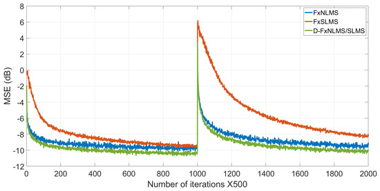
Figure 3.
Performance comparison between FxNLMS, FxSLMS and the proposed D-FxNLMS/SLMS algorithm.
Table 2.
Number of multiplications and additions required to perform the FxNLMS, FxSLMS and the proposed D-FxNLMS/SLMS.
4. Hardware Simulation
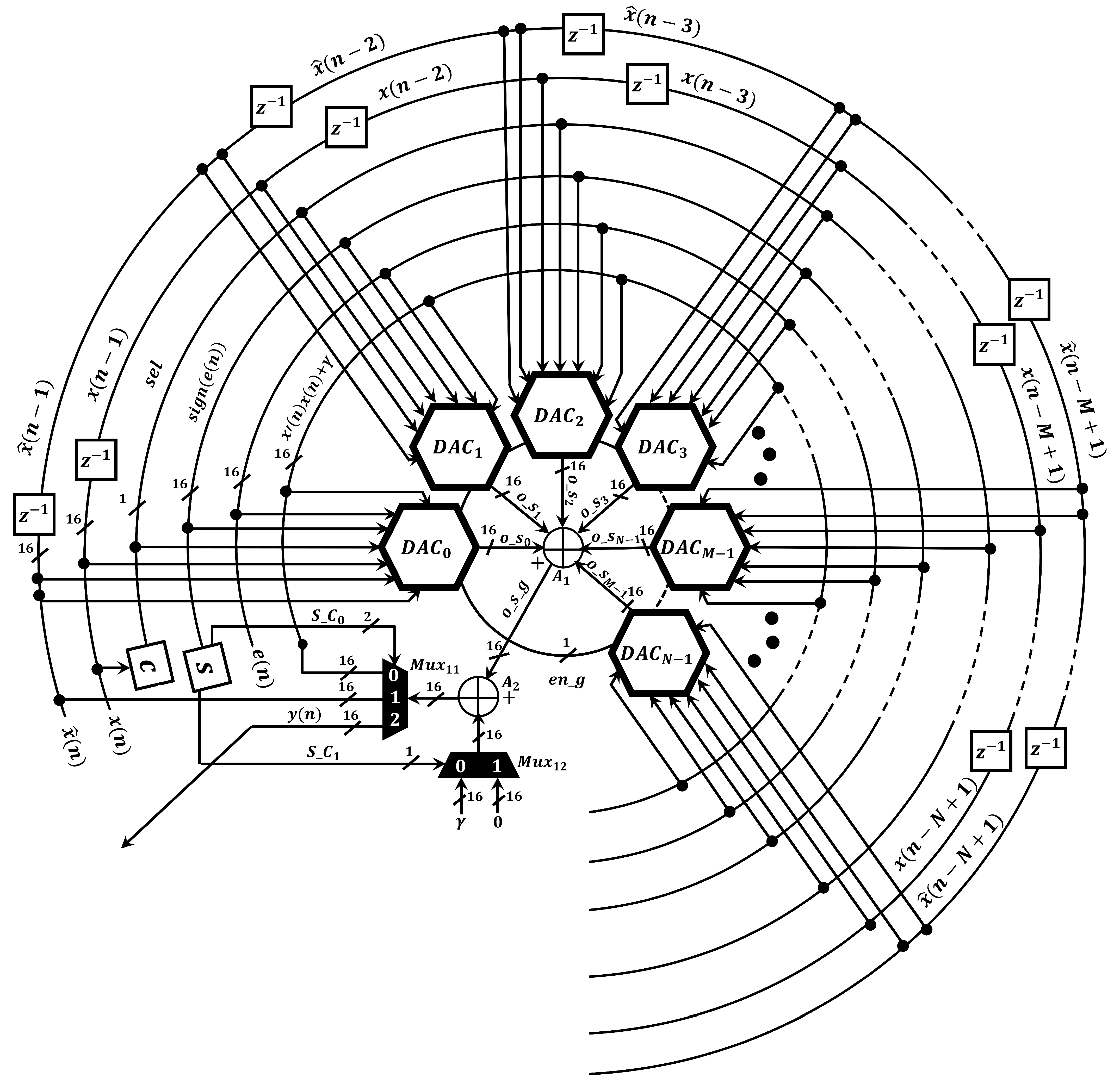
Once the proposed ANC structure was exhaustively validated in Matlab®, we designed the proposed spike-based hardware architecture to efficiently simulate the D-FxNLMS/SLMS algorithm. The proposed spike-based structure is mainly composed of dual active cores (DAC’s), as shown in Figure 4.
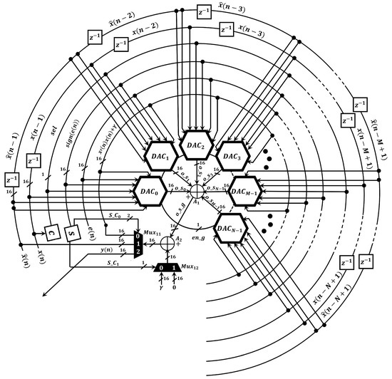
Figure 4.
General scheme of the proposed spike-based hardware architecture.
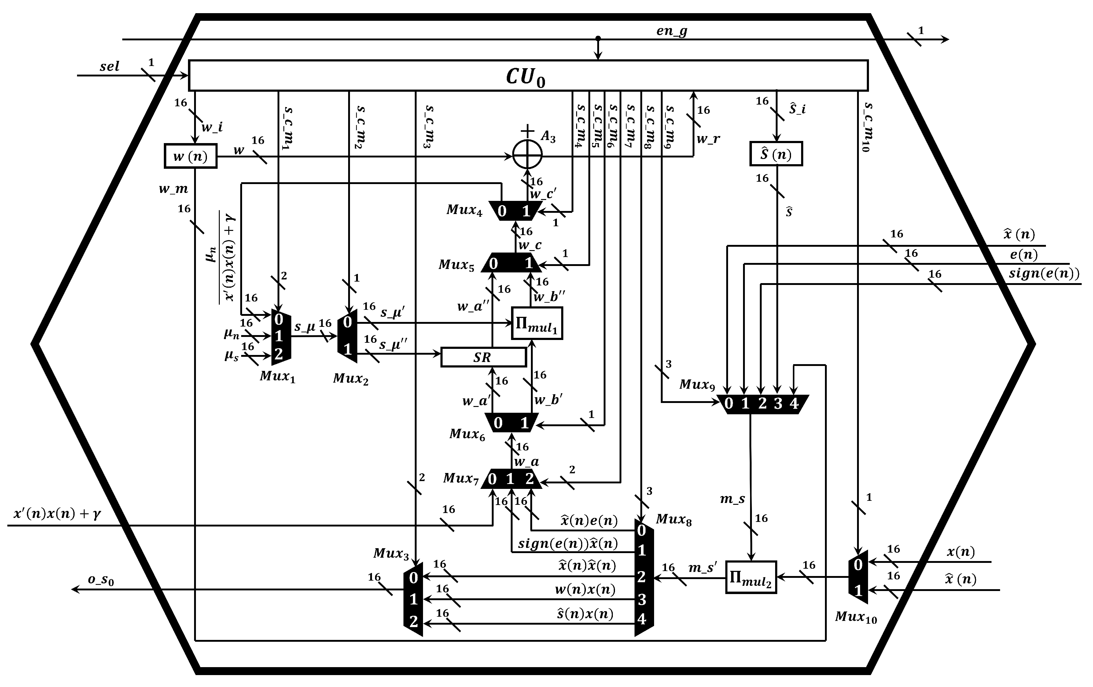
Here, we made intensive efforts for reducing the area consumption since the implementation of two adaptive algorithms in embedded devices demands a large area. To date, several convex combinations are considered to be theoretical approaches since their implementation is infeasible. One of the main factors is linked to the required number of multiplier circuits to simulate them and current embedded devices contain a limited number of these components. Here, we proposed a new spike-based hardware architecture, which maximizes the use of the existing neural multiplier [26], to efficiently compute the D-FxNLMS/SLMS algorithm. As can be observed in Figure 5, we design the DAC’s structure to support two adaptive algorithms by means of dynamic routing system, which is implemented by means of multiplexers and a control unit. In addition, each DAC contains two neural multipliers to perform either the FxNLMS or the FxSLMS algorithm. This have been possible since each neural multiplier requires a low number of neurons. For example, the implementation of 5-neuron multiplier circuit is equivalent to implement a conventional 16-bit multiplier circuit since 16 bits represents a range between 0 and 65,535, where each number can be composed of up to 5 digits.
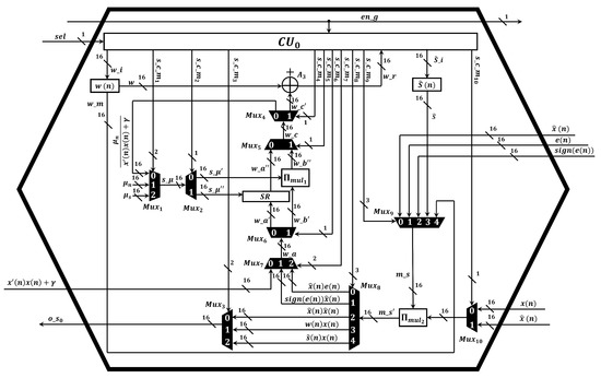
Figure 5.
Structure of the dual adaptive core.
4.1. Control Unit
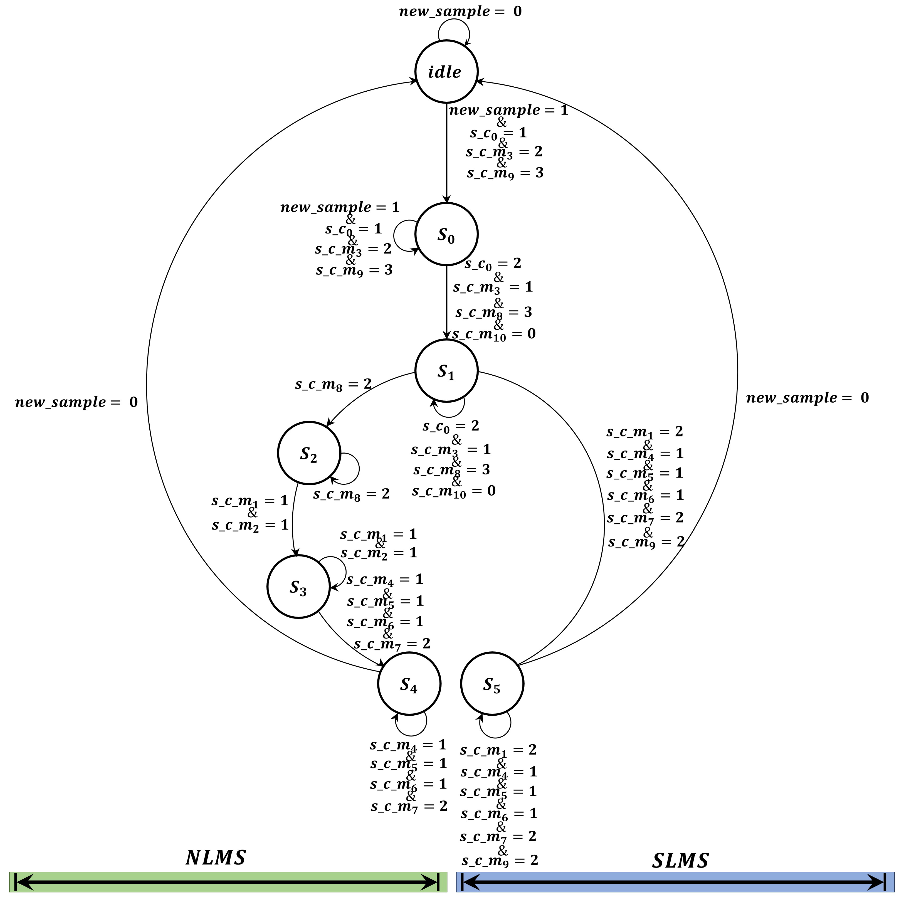
The control unit is responsible for controlling the data flow by means of the multiplexers to perform either the FxNLMS or the FxSLMS algorithm. Here, the control unit is based on a finite-state machine FSM and is composed of six states, as shown in Figure 6. The control unit of each DAC calculates either the FxNLMS or the FxSLMS algorithm by executing the following steps:

Figure 6.
State flow diagram of the control unit to perform either the FxNLMS or FxSLMS algorithm.
- Calculation of the signal . At the initial time, each DAC computes the filtered-x signal by performing the multiplication (). Therefore, these parameters are sent to multiplier via and . The result of the multiplication is sent to adder circuit to be added via .
- Calculation of the control signal . At this step, the neuronal multiplier performs the multiplication between , where these variables are fed through and . As previous step, the result is sent to adder circuit by means of .
- Calculation of the selection criteria. To perform this step, the digital component C is in charge of calculating the theoretical steady-state MSE. Once the component indicates which algorithm must be performed, either the FxNLMS algorithm or FxSLMS are executed as follows:
- –
- Simulation of the FxNLMS algorithm. If the FxNLMS algorithm is enabled, the neural multiplier computes . The result of the multiplication is sent to adder circuit to be added via . After that, the result of the addition along with the constant are processed by the adder circuit (see Figure 4). To perform the computation of the normalized variable step size, the variable and signal () are sent to the neural multiplier via ( and ), ( and ), respectively. The resulting signal ( ) is sent back to the shift register SR via ( and ). At this time, the shift register SR performs an intrinsically division by performing shifts to the right. Simultaneously, the multiplier performs its operation between and . Once there two operations were calculated, the results are sent to the adder circuit . In this manner, the result of the addition is used to update the FIR filter coefficients.
- –
- Simulation of the FxSLMS algorithm. If the FxSLMS algorithm is used, the multiplier performs its operation between and . The result is sent to the shift register SR to intrinsically perform a division. After that, the result is added to the filter coefficients to update them.
In general, the control unit executes its states to calculate the FxNLMS and FxSLMS algorithm by expending 55 and 43 clock cycles, respectively at a sampling rate of 8 KHz. In case of performing the simulation of a typical case (N = 1024), the spike-based hardware architecture requires 1024 DAC’s. Here, all DAC’s play an important role in the computation of the proposed algorithm since these components carry out two adaptive algorithms using the same unit. To implement this in the 5SGXEA7N2F45C2 FPGA, it requires 3800 logic elements (LE’s) from the available 622,000 LE’s, which represents 0.61% of the total area. On the other hand, the spike-based hardware architecture requires 0.44 s and 0.34 s to simulate the FxNLMS and FxSLMS algorithm, respectively, at each sampling period. This time was obtained by multiplying 55 and 43 clock cycles and the system clock period (8 ns). Therefore, the required execution time is fewer than a sampling time (125 s). Hence, the proposed architecture can be used in real-time ANC applications.
4.2. Proposed Graphical Unit Interface
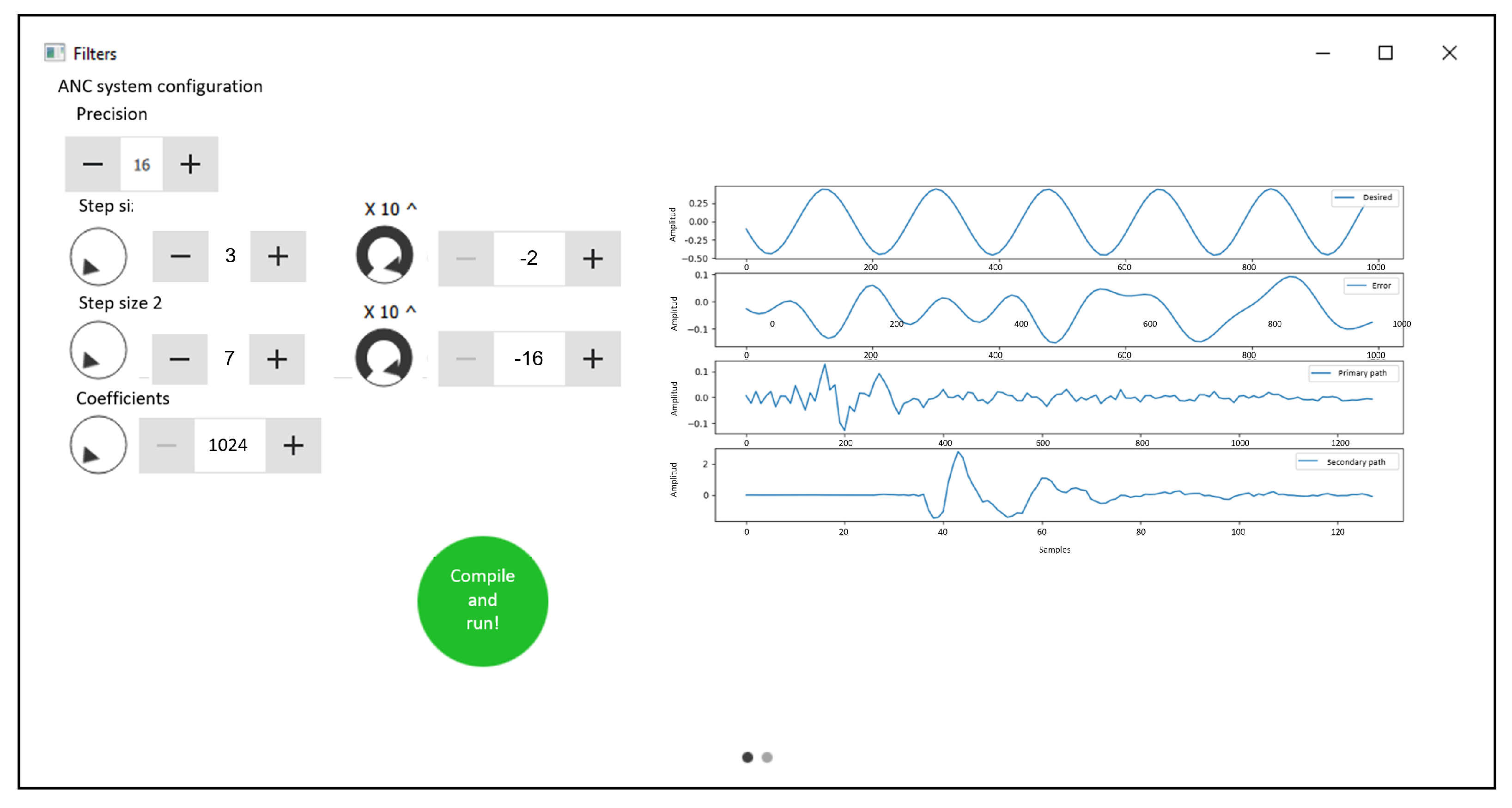
In this work, we develop a graphical user interfaces (GUI) to design, control, and monitor the spike-based hardware architecture. The description of the adaptive system parameters are done with the help of the proposed GUI. Here, this GUI generates files required to configure the spike-based hardware architecture, i.e., these files are exported to the FPGA via G-Ethernet connections to control the execution and graphically display the response of the ANC system for easy perception and analysis, as shown in Figure 7.

Figure 7.
GUI main window.
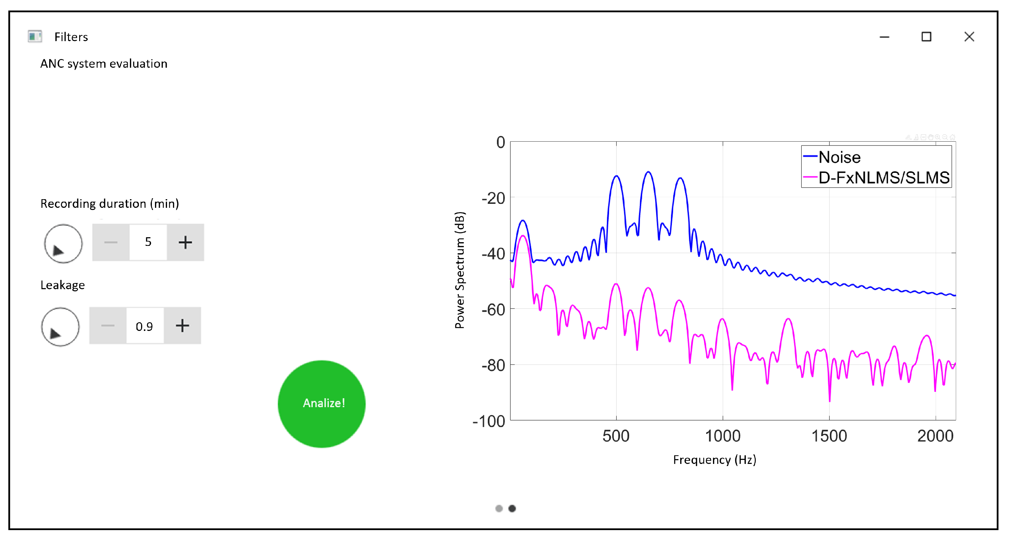
In addition, the proposed GUI displays the behavior of the power spectrum of the signals, as shown in Figure 8. In this way, the performance of the proposed algorithm in terms of noise cancellation can be evaluated.
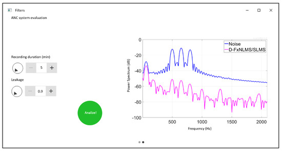
Figure 8.
Power spectrum analysis.
As can be observed from Figure 6, the text area displays the parameters (Precision, Step size 1, Step size 2 and Coefficients). Once the user has selected their values, these parameters are sent to the FPGA by clicking “Compile and run” button. At this moment, the FPGA sends back to the computer the behavior of the signals (Desired, Error, Primary path and Secondary path) to be analyzed by the user. In general, our contribution intends to provide a hardware/software tool that allows the prototyping of ANC systems faster than on CPU/GPU/DSP architectures but significantly cheaper than fabricating a customized neuromorphic chip. This could be potentially valuable to the computational signal processing engineering communities.
4.3. Experimental Results
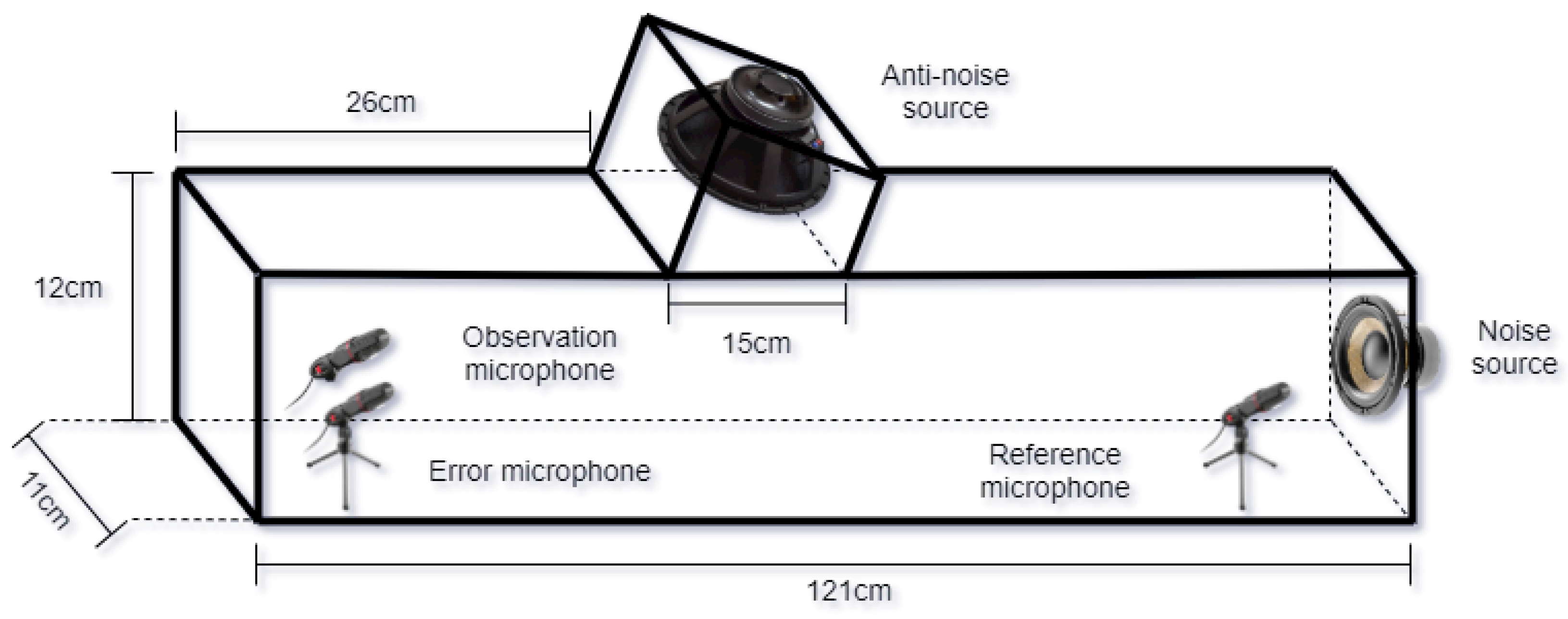
In this work, we carry out 1:1:1 ANC experiments in a medium-density fiberboard (MDF) duct. Specifically, the measurements of the duct were defined as L = 121 cm, W = 11 cm and H = 12 cm, as shown in Figure 9. Therefore, the aim of this experiment is to demonstrate that the proposed spike-based hardware architecture can be used in a practical ANC application.
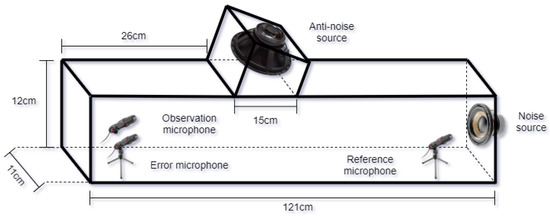
Figure 9.
Experimental set-up for active noise reduction in a duct.
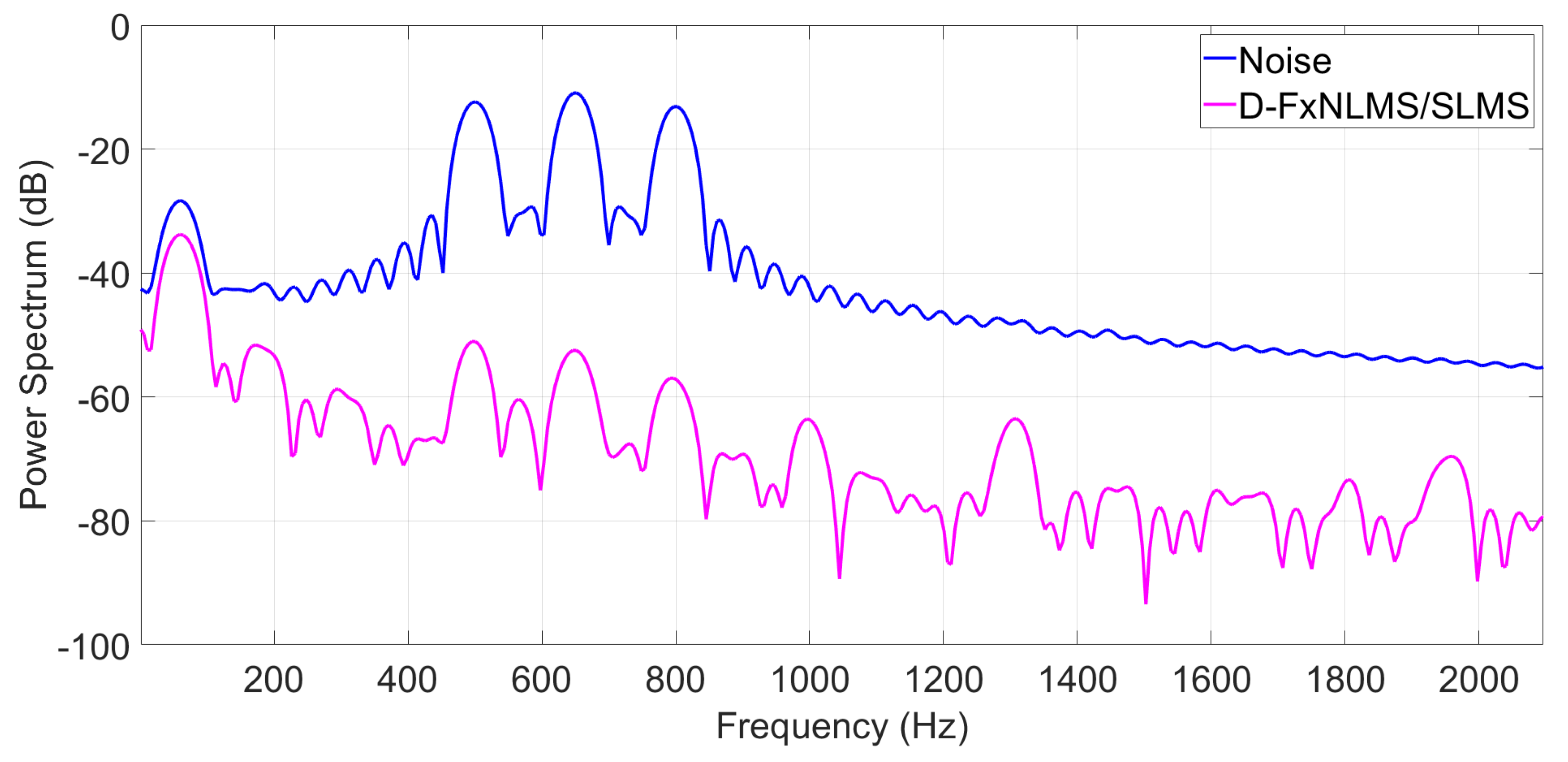
As can be observed from Figure 10, the single-channel ANC system is composed of anti-aliasing filters, a reference microphone, an error microphone, an amplifier, an antinoise source, an observation microphone and a spike-based hardware architecture. Specifically, the anti-aliasing filters were used to eliminate signals with high frequencies. The reference microphone and error microphone were employed to estimate the reference signal and the residual error signal, respectively. The amplifier and antinoise source were used to produce the control signal. The observation microphone was used to evaluate the performance of the ANC system. Finally, the spike-based hardware architecture generates the control signal. In general, the error signal is obtained by means of an error microphone, and then filtered by an anti-aliasing filter. The resulting analogue signal is converted to a digital signal to be computed by the spike-based hardware architecture. Once the proposed algorithm generated the control signal, the spike-based hardware architecture sends the analogue signal to the amplifier to guarantee the acoustic cancellation by means of the antinoise source. Here, we estimated the secondary path offline by means of LMS algorithm with 128 coefficients. In this way, we can easily acquire the acoustic characteristics between the reference microphone and error microphone. Moreover, we employed an adaptive filter with 1024 coefficients to generate the antinoise signal. On the other hand, we performed three experiments using three types of reference signals, an arbitrary multi-tonal input of 500 Hz, 650 Hz and 800 Hz, an AR(1) process and aircraft interior noise to evaluate the performance of the proposed ANC structure in the acoustic duct.
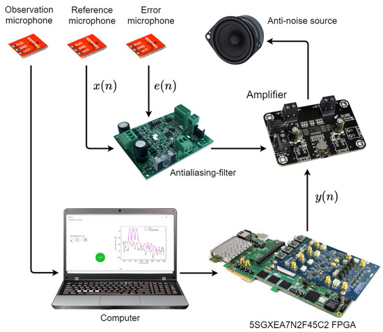
Figure 10.
Components of the ANC system.
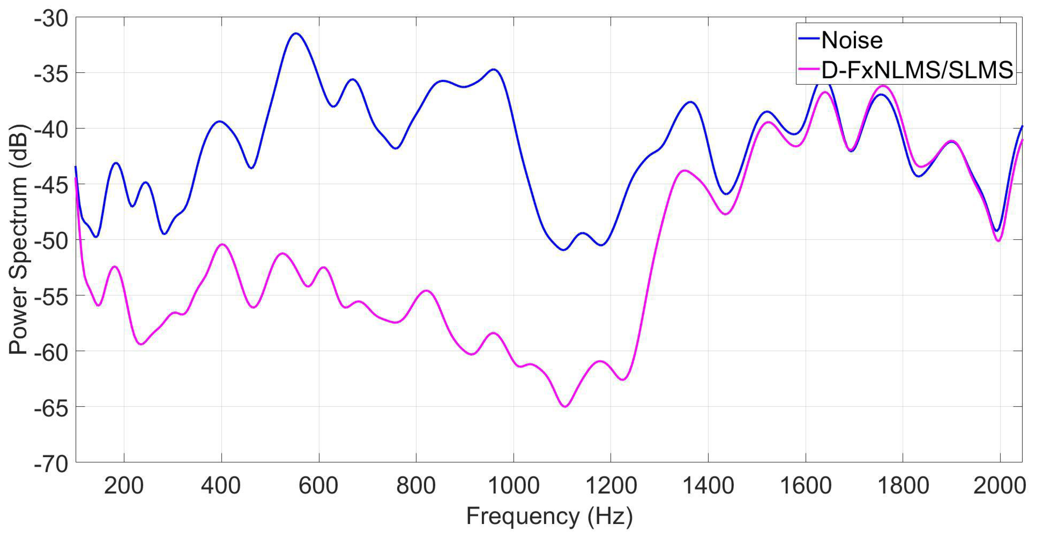
As can be observed from Figure 11, Figure 12 and Figure 13, the proposed algorithm can effectively attenuate noise by achieving an average noise reduction improvement of about 40 dB, 35 dB, and 10–25 dB, respectively. Apart from its effectiveness in noise cancellation, the proposed D-FxNLMS/SLMS algorithm exhibits a low computational cost since the FxNLMS algorithm is used fewer number of times in comparison with the use of FxSLMS algorithm, as shown in Table 3.
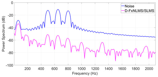
Figure 11.
Power spectrum of the error signal at observation microphone by taking into account a multi–tone as a reference signal.
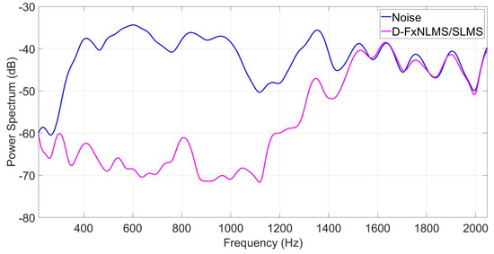
Figure 12.
Power spectrum of the error signal at observation microphone by taking into account an AR(1) process as a reference signal.

Figure 13.
Power spectrum of the error signal at observation microphone by taking into account an aircraft interior noise as a reference signal.
Table 3.
Updating percentage by processing three reference signals.
5. Conclusions
In this work, we present a new ANC structure in which two low-computational-cost adaptive filters were used. Specifically, we propose criteria to carry out the selection between them at different times. This selection is based on the comparison between the power of the error signal and the MSE theoretical level. At the initial filtering process, the proposed ANC structure uses a fast convergence speed adaptive algorithm. Once the error power overcomes the theoretical steady-state MSE, the update of the filter’s coefficients is performed by the low-computational-complexity algorithm. In this way, the proposed ANC structure expends lower number of multiplications and additions. As a consequence, the implementation of this algorithm in embedded devices was feasible and it can be applied in real-time ANC applications. Here, we proposed a new spike-based hardware architecture to create a compact device which can be used in portable ANC devices. Specifically, we propose a hardware architecture which can simulate different algorithms without resynthesizing the FPGA. Currently, this aspect has a big impact since most of the designs implemented in FPGA devices are considered to be final products making their integration in commercial portable electronic systems easy. Here, we design a dynamic routing circuit to perform two adaptive algorithms in each DAC, avoiding the implementation of each adaptive algorithm separately. As a consequence, a large amount of area is saved. In addition, the proposed architecture can be configured by means of a GUI, which is beneficial to the user since in the development of practical ANC prototypes many experimental tests are required. Part of future work will be dedicated to developing multichannel ANC systems since the proposed spike-based architecture expends a very low area consumption by supporting a single-channel ANC system.
Author Contributions
Conceptualization, G.S.; methodology, J.G.A. and G.S.; software, E.P. and E.R.A.; validation, E.P. and E.R.A.; formal analysis, Á.V.; investigation, Á.V.; resources, Á.V.; data curation, H.P.; writing—original draft preparation, J.G.A. and G.S.; supervision, G.S. and J.G.A.; funding acquisition, J.C.S. All authors have read and agreed to the published version of the manuscript.
Funding
The authors would like to thank the Instituto Politécnico Nacional for the financial support.
Conflicts of Interest
The authors declare no conflict of interest.
References
- Loiseau, P.; Chevrel, P.; Yagoubi, M.; Duffal, J.M. Robust active noise control in a car cabin: Evaluation of achievable performances with a feedback control scheme. Control. Eng. Pract. 2018, 81, 172–182. [Google Scholar] [CrossRef]
- Gäbel, G.; Millitzer, J.; Atzrodt, H.; Herold, S.; Mohr, A. Development and implementation of a multi-channel active control system for the reduction of road induced vehicle interior noise. Actuators 2018, 7, 52. [Google Scholar] [CrossRef] [Green Version]
- Mazur, K.; Wrona, S.; Pawelczyk, M. Active noise control for a washing machine. Appl. Acoust. 2019, 146, 89–95. [Google Scholar] [CrossRef]
- Cho, H.C.; Park, S.W.; Lee, K.S.; Kim, N.H. A novel multiple-channel active noise control approach with neural secondary-path model for interior acoustic noise attenuation of railway train systems. IET Signal Process. 2012, 6, 772–780. [Google Scholar] [CrossRef]
- Patel, V.; Cheer, J.; Fontana, S. Design and Implementation of an Active Noise Control Headphone With Directional Hear-Through Capability. IEEE Trans. Consum. Electron. 2019, 66, 32–40. [Google Scholar] [CrossRef]
- Liu, L.; Beemanpally, K.; Kuo, S.M. Application of multi-channel hybrid active noise control systems for infant incubators. Noise Control. Eng. J. 2013, 61, 169–179. [Google Scholar] [CrossRef]
- Liu, L.; Kuo, S.M.; Raghuathan, K.P. An audio integrated motorcycle helmet. J. Low Freq. Noise Vib. Act. Control. 2010, 29, 161–170. [Google Scholar] [CrossRef]
- Murao, T.; Shi, C.; Gan, W.S.; Nishimura, M. Mixed-error approach for multi-channel active noise control of open windows. Appl. Acoust. 2017, 127, 305–315. [Google Scholar] [CrossRef]
- Cheer, J.; Elliott, S.J. Active noise control of a diesel generator in a luxury yacht. Appl. Acoust. 2016, 105, 209–214. [Google Scholar] [CrossRef] [Green Version]
- Serizel, R.; Moonen, M.; Wouters, J.; Jensen, S.H. Binaural integrated active noise control and noise reduction in hearing aids. IEEE Trans. Audio Speech Lang. Process. 2012, 21, 1113–1118. [Google Scholar] [CrossRef] [Green Version]
- Liu, J.; Li, C. Active soundproof earmuffs system with passive noise insulation structure compensation. Appl. Acoust. 2020, 165, 107321. [Google Scholar] [CrossRef]
- Zhao, T.; Liang, J.; Zou, L.; Zhang, L. A new FXLMS algorithm with offline and online secondary-path modeling scheme for active noise control of power transformers. IEEE Trans. Ind. Electron. 2017, 64, 6432–6442. [Google Scholar] [CrossRef]
- Kim, H.W.; Park, H.S.; Lee, S.K.; Shin, K. Modified-filtered-u LMS algorithm for active noise control and its application to a short acoustic duct. Mech. Syst. Signal Process. 2011, 25, 475–484. [Google Scholar] [CrossRef]
- Zhao, S.; Qiu, X.; Lacey, J.; Maisch, S. Configuring fixed-coefficient active control systems for traffic noise reduction. Build. Environ. 2019, 149, 415–427. [Google Scholar] [CrossRef]
- Arenas-Garcia, J.; Azpicueta-Ruiz, L.A.; Silva, M.T.; Nascimento, V.H.; Sayed, A.H. Combinations of adaptive filters: Performance and convergence properties. IEEE Signal Process. Mag. 2015, 33, 120–140. [Google Scholar] [CrossRef]
- Vazquez, A.A.; Avalos, J.G.; Sanchez, G.; Sanchez, J.C.; Perez, H. A Comparative Survey of Convex Combination of Adaptive Filters. IETE J. Res. 2020, 1–11. [Google Scholar] [CrossRef]
- Ferrer, M.; Gonzalez, A.; de Diego, M.; Pinero, G. Convex combination filtered-x algorithms for active noise control systems. IEEE Trans. Audio Speech Lang. Process. 2013, 21, 156–167. [Google Scholar] [CrossRef] [Green Version]
- George, N.V.; Gonzalez, A. Convex Combination of Nonlinear Adaptive Filters for Active Noise Control. Appl. Acoust. 2014, 76, 157–161. [Google Scholar] [CrossRef]
- Al Omour, A.M.; Zidouri, A.; Iqbal, N.; Zerguine, A. Filtered-x least mean fourth (FXLMF) and leaky FXLMF adaptive algorithms. EURASIP J. Adv. Signal Process. 2016, 1, 39. [Google Scholar] [CrossRef] [Green Version]
- Song, P.; Zhao, H. Filtered-x generalized mixed norm (FXGMN) algorithm for active noise control. Mech. Syst. Signal Process. 2018, 107, 93–104. [Google Scholar] [CrossRef]
- Song, P.; Zhao, H. Filtered-x least mean square/fourth (FXLMS/F) algorithm for active noise control. Mech. Syst. Signal Process. 2019, 120, 69–82. [Google Scholar] [CrossRef]
- Vázquez, A.; Pichardo, E.; Avalos, J.G.; Sánchez, G.; Martínez, H.M.; Sánchez, J.C.; Pérez, H.M. Multichannel active noise control based on filtered-x affine projection-like and LMS algorithms with switching filter selection. Appl. Sci. 2019, 9, 4669. [Google Scholar] [CrossRef] [Green Version]
- Gonzalez, A.; Ferrer, M.; de Diego, M.; Roig, C.; Piñe, G. Convex combination strategies for active noise control on multicore processors. In Proceedings of the 17th International Congress on Sound and Vibration (ICSV 17), Cairo, Egypt, 18–22 July 2010; pp. 309–316. [Google Scholar]
- Felix, F.B.; de Castro Magalhaes, M.; de Souza Papini, G. An Improved ANC Algorithm for the Attenuation of Industrial Fan Noise. J. Vib. Eng. Technol. 2021, 9, 279–289. [Google Scholar] [CrossRef]
- Kuo, S.M.; Morgan, D.R. Active noise control: A tutorial review. Proc. IEEE 1999, 87, 943–973. [Google Scholar] [CrossRef] [Green Version]
- Sanchez, G.; Avalos, J.G.; Vazquez, A.; Garcia, L.; Frias, T.; Toscano, K.; Perez, H. A compact neuromorphic architecture with dynamic routing to efficiently simulate the FXECAP-L algorithm for real-time active noise control. Appl. Soft Comput. 2021, 91, 106233. [Google Scholar] [CrossRef]


Publisher’s Note: MDPI stays neutral with regard to jurisdictional claims in published maps and institutional affiliations. |
© 2021 by the authors. Licensee MDPI, Basel, Switzerland. This article is an open access article distributed under the terms and conditions of the Creative Commons Attribution (CC BY) license (https://creativecommons.org/licenses/by/4.0/).