Article

Embroidered Βow-Tie Wearable Antenna for the 868 and 915 MHz ISM Bands

by
Theodoros N. Kapetanakis
1,
Martin Pavec
2,
Melina P. Ioannidou
3,
Christos D. Nikolopoulos
1,4,
Anargyros T. Baklezos
1,4,
Radek Soukup
2 and
Ioannis O. Vardiambasis
1,*
1
Department of Electronic Engineering, Hellenic Mediterranean University, 73133 Chania, Crete, Greece
2
Department of Materials and Technology (KET), University of West Bohemia, 30100 Pilsen, Czech Republic
3
Department of Information and Electronic Engineering, International Hellenic University, 57400 Thessaloniki, Greece
4
School of Electrical and Computer Engineering, National Technical University of Athens, 15780 Athens, Greece
*
Author to whom correspondence should be addressed.
Electronics 2021, 10(16), 1983; https://doi.org/10.3390/electronics10161983
Submission received: 10 July 2021 / Revised: 12 August 2021 / Accepted: 14 August 2021 / Published: 17 August 2021
(This article belongs to the Section Microwave and Wireless Communications)

Abstract

:
A textile, embroidered antenna, based on the fractal shape of the Sierpinski triangle, is designed in this paper for operation in the European free Industrial Scientific and Medical (ISM) 863–870 MHz band, as well as in the 902–928 MHz band designated for ISM applications in North and South America. Several prototypes have been fabricated by employing different stitch patterns and thread materials. The effect of the fabrication parameters on the performance of the proposed antenna is investigated through measurements and simulations, with the results being in good agreement. The antenna exhibits attractive characteristics such as wide bandwidth, relatively stable radiation patterns, as well as robustness in washing. Several tests reveal that convex and concave bent conditions do not affect the coverage of the aforementioned ISM bands, despite the shift of the resonant frequency in some cases. Moreover, the SAR values resulting from simulations are below the corresponding thresholds suggested by international guidelines.

1. Introduction

Embroidery is an advanced technique that allows integration of flexible antennas and sensors into clothing; it draws strong interest nowadays because embroidered and textile antennas may serve as a smart interface between humans and technology. Modern concepts, such as the Internet of Things (IoT), demand everything to be connected in a single network. Thus, the possibility of “wearing” an antenna offers to humans the opportunity to be part of the network [1]. Embroidery gains ground over other more conventional manufacturing techniques for wearable antennas, such as printing the antenna by using etching or attaching it to the fabric, because it enables mass production of garments and it does not require any intermediate material between the antenna and the (textile) substrate, since the former is fully embedded into the latter [2]. Moreover, the process of embroidery allows for the implementation of customized designs and colorful, aesthetic shapes as well as the incorporation of the antenna into logos [3].
The design and fabrication of embroidered antennas may be a challenging task. An important requirement that should be satisfied is the mechanical robustness of the fabrics, since the softness and flexibility of the latter, albeit essential in wearable systems, may lead to a performance reduction of the antenna, due to bending, stretching, folding, compression, and water absorption [4]. Moreover, low-profile, light weight, wireless connection and reasonable cost are required in modern, wearable antennas [5]. The fabrication parameters, such as the stitch direction and spacing, may have a significant impact on the antenna performance [6], whereas another issue to be addressed is the repeatability of the employed fabrication process [7]. A matter of concern may be the antenna–body interaction, since it is well known that the antenna characteristics may be affected by the presence of the human body [8,9,10,11,12]. In addition, it is essential to satisfy the international regulations for the absorption of the electromagnetic energy by the human tissues [13,14,15].
Embroidered and wearable antennas offer a wide range of applications including, among others, radio frequency identification (RFID) [16,17,18], cellular reception, which may be achieved by replacing the antenna embedded in the cell phone with a body-worn version [9], electromagnetic energy harvesting [1], as well as medical monitoring and healthcare; for example, the integration of a wearable antenna into the patient’s garment and a remote transmission of vital readings to a healthcare professional may allow treatment at home [6]. Furthermore, location tracking and body worn navigation may be performed by using broadband-embroidered antennas; the latter may be part of an “off-body” network with numerous applications in the emergency services and security areas, such as the operation of rescue teams in poor visibility conditions [10].
The papers that appear in the literature for the design and fabrication of embroidered antennas are countless; a few, recent, indicative works are cited below. Automated embroidery of conductive e-threads has been applied for the realization of logo-shaped textile antennas [3]; promising e-fibers, with high geometrical precision, have been proposed [19] and used for the fabrication of a load-bearing spiral antenna [7]. Other configurations include an embroidered slotted patch-like multiband antenna [9], a broadband spiral antenna for off-body communications [10], a textile folded rectangular half-mode cavity antenna [20], a non-uniform meshed patch that reduces the usage of the conductive thread [5], a mixed embroidered and woven cavity-backed slot antenna [21], a four-layered, conventionally embroidered antenna with an end-to-end slot with the layers sewn together [14], a near-field communication antenna designed in the shape of a rectangular spiral coil [17], and an embroidered meander ring dipole [22]. Recently, antenna arrays have been realized in textile technology, such as a wideband array consisting of three overlapping dipoles for on-body operation [23] and a dual-polarized textile antenna array consisting of a group of embroidered patches [15].
A textile embroidered antenna is proposed in this paper for the unlicensed 863–870 MHz and 902–928 MHz ISM bands. The external boundary of the antenna follows the shape of a bow tie, whereas the Sierpinski (SPK) fractal geometry is applied for the formation of the final layout. The SPK fractal geometry has been already used in the literature for the design of antennas; so far, the fabrication of such antennas has consisted in printing the SPK fractal shape on a conventional substrate, such as FR4 [24,25,26], while an attractive feature is that they exhibit “miniaturization characteristics”, as shown in [25]. However, as far as we could determine, an embroidered bow tie antenna, based on the fractal shape of the SPK triangle, has not been implemented before. Thus, the main contribution of this paper is the fabrication of the SPK bow tie antenna by using embroidery techniques. Several, slightly different, prototypes are embroidered on a fabric substrate by using conductive threads, a detailed description of which is provided in Section 2. The antenna performance is investigated in Section 3 through measurements and simulations. The effect of bending and washing on the operation of the antenna is, also, examined therein. The specific absorption rate (SAR) is assessed and compared with the limits provided by International Standards. In addition, comparison with other recent works is presented therein and it is demonstrated that, although the efficiency and the return losses of the proposed antenna are in the middle of the range reported in the literature, it exhibits a broader bandwidth among similar structures. Finally, Section 4 comprises the conclusions of this work.

2. Materials and Methods

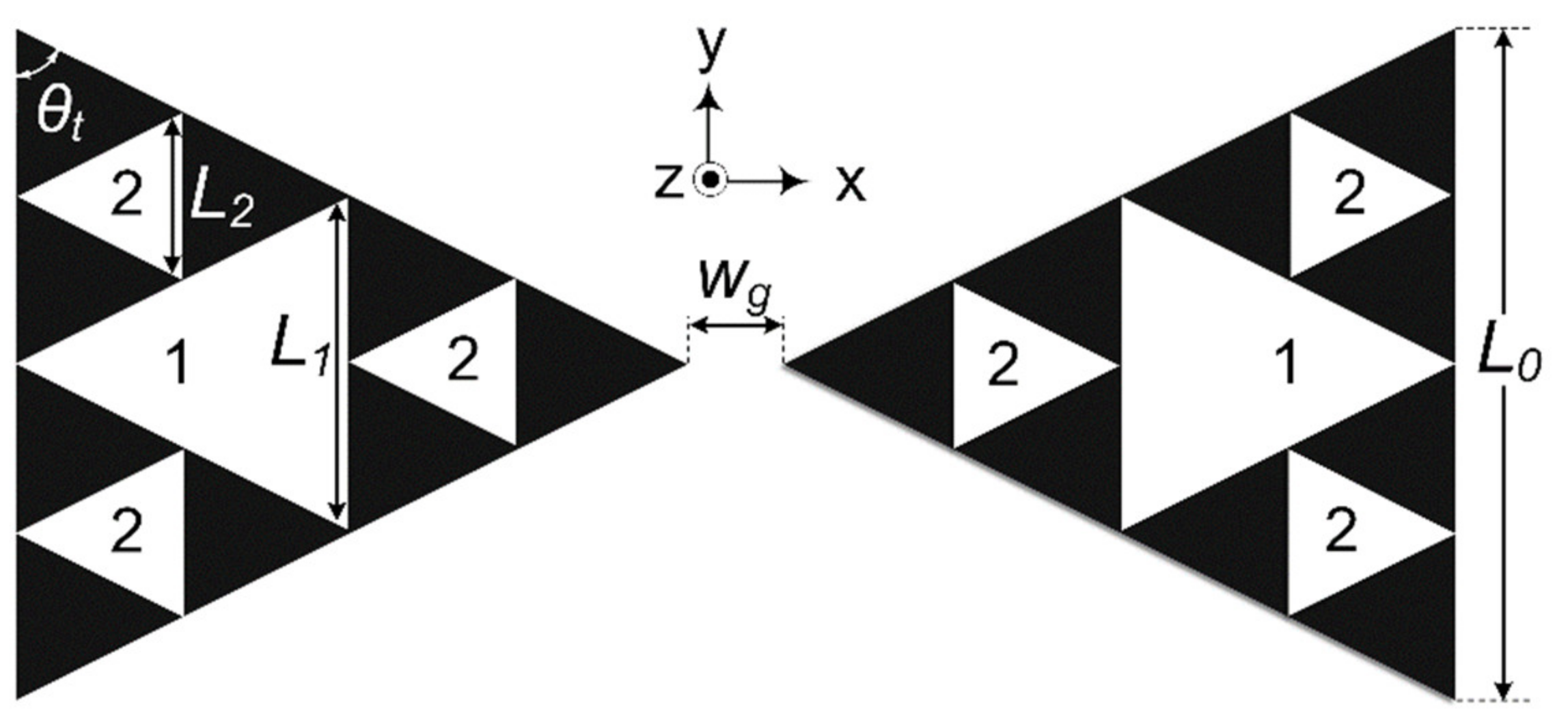
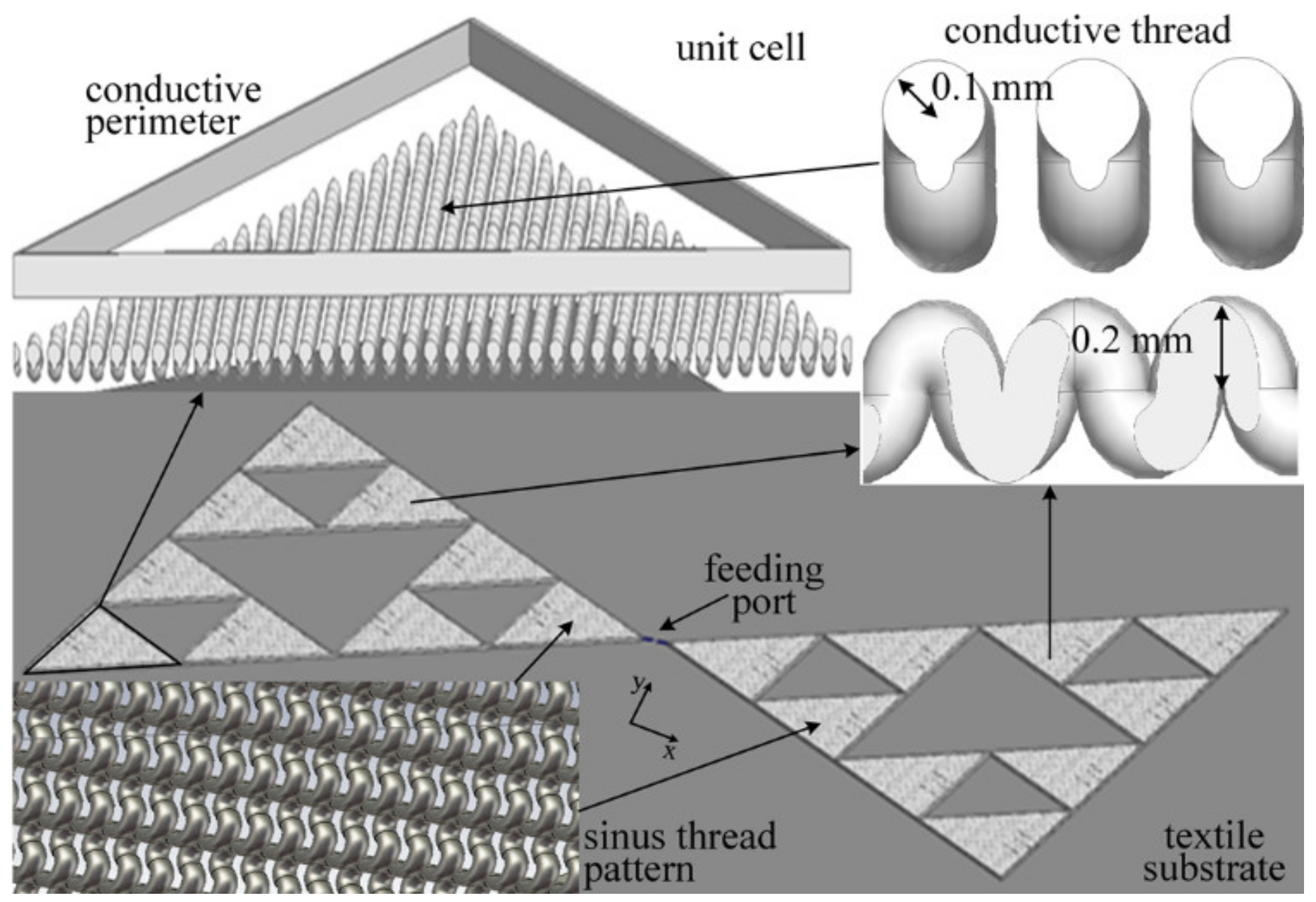
2.1. SPK Fractal-Based Design and Embroidery Process

The design of the proposed antenna uses a bow tie as a generator and is based on the SPK fractal geometry [27,28]. The original shape consists of two back-to-back equilateral triangles; a small gap, denoted as wg, exists between them. The first step is taken by removing one inverted equilateral triangle from each main triangular shape, whereas a second iteration leads to the configuration shown in Figure 1, i.e., one equilateral triangle is removed from each triangle created in the previous stage. The area removed in each iteration is given by [25]:
A N = 1 3 i = 1 N 3 / 4 i
Herein, the number of iterations is N = 2 [29], meaning that, if we assume that the area of the original triangle is equal to 1, then a total area of A2 = 1/4 + 3/16 is removed after the 2nd iteration.
Seven similar (but not identical), antennas were constructed by embroidering the pattern of Figure 1 on a Dupont Nomex meta-aramid fabric, composed of 93% Nomex, 5% Kevlar, and 2% carbon, referred to as Nomex hereafter. The relative dielectric constant of the aforementioned substrate was εr = 3.5, its surface resistivity per square was 1012 Ω, and its loss tangent was tanδ = 0.006. Nomex is a flame-resistant textile commonly used for petrochemical protective suits [30]. The sewing machine Bernina QE750, equipped with a special module for embroidering, was used for the fabrication of the bow-tie antenna prototypes. The latter have been manufactured by using different thread materials and stitch patterns, in order to investigate the dependence of the antenna characteristics on the aforementioned embroidery techniques. Moreover, the prototypes differ from each other slightly in dimensions due to their home-made construction.
The exact geometrical and fabrication characteristics of each prototype, together with the corresponding nominal values, are given in Table 1. L0 stands for the half-length of the structure and L1 (L2) is the length of the side of each triangle after the first (second) iteration (Figure 1). Besides, the thread material and the stitch pattern used for the embroidery are listed in Table 1. The symbol “S” (“B”) stands for a Clevertex silver (brass) hybrid conductive sewing thread. The silver hybrid thread is composed of 4 strands; each one contains 33 polyester (PES) fibers and includes one silver plated copper (Cu/Ag) microwire. The brass hybrid thread is composed of 2 strands; each strand contains 48 PES fibers and 4 brass microwires. Each PES monofilament has an average diameter of 14.5 µm, whereas the diameter of the brass (or Cu/Ag) microwire is 30 µm, on average. The linear resistance is 6.5 Ω/m for the silver hybrid thread and 8.9 Ω/m for the brass hybrid thread (nominal values @ 20 °C). The hybrid threads were developed and tested by the University of Bohemia in Pilsen, in cooperation with VUB Co. Ltd. (Usti nad Orlici, Czech Republic) [31].
A low, medium, or high stitch pattern was used. The high stitch pattern corresponds to 0.1 mm distance between two adjacent seam lines, whereas the distance becomes 0.2 (0.3) mm for the medium (low) stitch pattern. The “1” in the line labeled as “conductive side” means that the conductive thread was used only on one side of the fabric, whereas “2” denotes that both sides of the fabric were embroidered using conductive thread. A picture of the prototype, named “S1Ha” in Table 1, is presented in Figure 2; the antenna is fed at the center point between the two triangular arms.
The connection of a mobile device to a textile antenna is a challenging task. An easy and practical way, suitable for prototyping and measurements, may be through the use of a coaxial cable such as the one shown in Figure 2. Another promising solution may be an embroidered transmission line. It should be noted that the hybrid threads and the textile substrate used for the fabrication of the proposed antennas are resilient to high temperatures, allowing the use of conventional soldering methods for various connector types, such as SMAs, UFLs, and FMEs. Moreover, a cutting-edge method may be to embed the mobile device and the antenna in an all-textile PCB, but the design and fabrication of such embedded systems is beyond the scope of this paper.

2.2. Modeling, Simulation and Measurements

Several experimental and simulation tests have been performed in order to assess the performance of the antenna and its dependence on the thread material and the stitch pattern. Measurements were conducted by using an HP 8714ET analyzer, whereas simulations were performed by using the CST Studio Suite 2021 software package.
The dimensions of the SPK fractal bow tie antenna satisfy the relationship L0 = 2L1 = 4L2. By using CST, we developed our own model (not inherent in any commercial software) for the simulation of the proposed embroidered antenna. The model was based on the repetition of a “unit cell”, which is an equilateral triangle with side length equal to 12 mm (Figure 3). This triangle comprises seam lines (unequal in length) parallel to each other; the distance between two adjacent seam lines is 0.1 mm (high stitch pattern). The thread used is actually a cylindrical structure with a of radius 0.1 mm, and is sewed around the (textile) substrate in a sinus-like pattern, forming the seam line. The distance between the two needle penetrations is 0.2 mm. A conductive triangular perimeter, with a width of 0.2 mm, encloses the unitary embroidered pattern in order to feed all the threads with current. Once the “unit-cell” is complete, it is replicated according to the Sierpinski pattern of Figure 1 to form the complete embroidered antenna.
We aimed at designing an embroidered textile for the ISM 868 MHz and 915 MHz frequency bands and the design procedure was initialized by using parameters taken from [25] for its microstrip counterpart. Since L0 and L1 obviously depend on L2, the most important design parameters are L2 and wg; their optimum values were evaluated by using the CST’s optimization tool. The values of all parameters, as obtained from CST, are given in the last column of Table 1.

3. Results

3.1. Experimental and Simulation Results in Free Space

Firstly, measurements in free space under usual indoor environmental conditions (temperature 19 °C and humidity 67%), were conducted for all prototypes. Table 2 summarizes the measured characteristics of the prototypes, as well as the corresponding simulation results. The resonant frequency fc, the magnitude of S11, and the Voltage Standing Wave Ratio (VSWR) at fc are listed in the first three lines of Table 2, respectively. The −10 dB bandwidth (BW) is given in the last two lines, while f1 and f2 stand for the lower and upper limit, respectively, of the aforementioned BW.
The first remark about Table 2 is that the unlicensed 902–928 MHz ISM band is covered by all antennas, albeit the performance of the prototypes may vary, depending on their fabrication and geometrical characteristics. Moreover, most of the prototypes (i.e., S1M, S1Ha, B1Ha, B1Hb, and partly S1L) offer coverage of the 863–870 MHz ISM band, too. Table 2 suggests that the measured results are better than the simulated ones; for example, the measured −10 dB BW of the prototype S1Ha is 4.4% greater than the simulated BW for the antenna with silver hybrid sewing thread. Generally, the prototypes fabricated with brass hybrid thread exhibited lower S11 @ fc, as well as broader −10 dB BW, than those embroidered with silver hybrid sewing thread. For example, the reflection coefficient (at the resonant frequency) of the prototype B1Ha is about 6.5 dB better than that of S1Ha, and its −10 dB BW is 6.4% greater. Moreover, a comparison between the prototypes B1Ha and B1Hb demonstrates that they both exhibit a relatively great BW and, regarding the S11 @ fc, they perform nearly the same; the lower resonant frequency of B1Hb may be attributed to its (slightly) greater dimensions. In regards to the prototypes S1Ha and S1Hb, the (slightly) greater dimensions of the former result in the covering of both ISM bands.

3.2. Effect of the Human Body

Consequently, the antenna was mounted on a human’s chest with a thin t-shirt in between, in an attempt to estimate the effect of the human body on the performance of the prototypes. The measured reflection coefficient, i.e., the magnitude of S11, is plotted in Figure 4; the prototypes, named as “S1Ha” and “B1Ha” in Table 1, are considered in Figure 4a,b, respectively. The dashed curve corresponds to concave natural bending, i.e., the backside of the antenna is in contact with the t-shirt, whereas the dotted curve represents convex natural bending with the front side of the antenna mounted on the t-shirt. Moreover, measurement (solid curve) and simulation (solid curve with markers) results, when the antenna was in free space, are included in Figure 4 for reference.
It may be verified from Figure 4a that the measured −10 dB BW, which is 166 MHz (17.3%) for the S1Ha prototype in free space, is increased to 343 MHz (50.7%), i.e., 619–962 MHz, when the antenna is body-mounted in a concave manner (dashed curve), whereas it reaches 430 MHz (52%), i.e., 594–1024 MHz, with the backside of the antenna mounted on a human’s chest (dotted curve). Although there is a remarkable difference in the BW of the free-space and the body-mounted antenna, both ISM bands are covered in all cases examined. A similar behavior is depicted in Figure 4b for the B1Ha prototype. The −10 dB BW of the latter, when it is body-mounted, is significantly broader compared to its free space BW. Specifically, the BW of the B1Ha prototype, body-mounted in a concave manner (dashed curve), is 386 MHz (47.4%), i.e., 646–1032 MHz, and it increases to 427 MHz (52%) when the antenna is body-mounted in a convex manner (dotted curve). The increase of the BW when the antenna is mounted on a human body may be attributed to the fact that the latter acts as an additional substrate with large dimensions and high permittivity that affects the antenna’s performance.

3.3. Performance under Bent Conditions

The antenna behavior has been investigated under both the x- and y-axis’ bent conditions, as shown in Figure 5. The fabric was mounted on a PVC cylindrical tube, with a length of 50 cm and εr = 4, either from the backside (Figure 5a,c, i.e., concave), which is non-conductive for all prototypes except S2H, or from the front (conductive) side (Figure 5b,d, i.e., convex). Four different tube diameters have been considered, i.e., d = 70, 90, 100, 130 mm, the thickness of each tube being 2, 2, 3, and 4 mm, respectively. The magnitude of S11 is plotted in Figure 6 when the antenna is bent in a concave manner, along y-axis, as shown in Figure 5c; Figure 6a,b refers to the S1Ha and the B1Ha prototypes, respectively. The curve with markers depicts the simulation results for S11 (dB) when the antenna is in free space; it is identical to the corresponding curve of Figure 4 and is included for reference.
Figure 6 suggests that the resonant frequency fc of the bent antenna decreased as compared to fc in free space. Specifically, fc of the bent S1Ha prototype (Figure 6a) is found somewhere in the range 842–855 MHz, depending on the tube diameter, whereas the free space resonant frequency of the same antenna is 957.2 MHz (Table 2). In regards to the fc of the bent B1Ha prototype (Figure 6b), the lowest value, i.e., 858 MHz, occurs for d = 100 mm (dotted curve) and the maximum value, fc = 959 MHz, corresponds to d = 70 mm (continuous curve), whereas the resonant frequency of the same prototype in free space is 961.4 MHz (Table 2). However, due to the wide BW of the antenna, the aforementioned shift of fc may not affect its operation under bent conditions, since both ISM bands fall within the −10 dB BW of the bent antenna in all cases considered. The aforementioned remark holds true for all bent conditions tested, albeit the entire set of results cannot be presented herein due to limited space. According to other measurements not shown in Figure 6, the −10 dB BW of the bent S1Ha (B1Ha) prototype was found roughly between 200 and 300 MHz, depending on the bent conditions, with an average value of 237 (273) MHz. The considerable BW expansion of the bent antennas in Figure 4 and Figure 6 may be attributed to the greater volume occupied by the antenna due to bending, as well as to the presence of an additional substrate [32].
The deviation of the resonant frequency under all bent conditions shown in Figure 5, due to bending, is depicted in Figure 7 for four different tube diameters. The deviation percentage is calculated as 100% × |fcbfc0|/fc0, where fc0 and fcb are the resonant frequencies before and after bending, respectively. Figure 7 suggests that the shift in the resonant frequency due to bending does not exceed 20% for all cases examined. The superiority of the brass hybrid conductive sewing thread over the silver one, in regards to the fc deviation, for small tube diameters, may be observed in the bar chart of Figure 7. For example, for a 70 mm tube diameter, the resonant frequency of the B1Ha prototype, deviates from its free space value by less than 7%, whereas the corresponding detuning for the S1Ha prototype may reach 18%, depending on the bent conditions.

3.4. Washing Tests

Subsequently, the performance of the proposed antenna has been investigated after 1, 2, 3, 5, and 10 machine washing cycles, using liquid or powdered detergent, with the following parameters: temperature 40 °C, speed 400 rpm, and duration of each cycle 90 min. After each washing cycle, the prototype was dried in the tumble dryer, but not ironed. The coaxial cable was disconnected for washing and resoldered after drying. Results for the prototype B1Hb are shown in Table 3; the first column (i.e., washing cycle “0”) is the same as the corresponding column of Table 2 and is included for reference.
Table 3 indicates that, even after 10 washing cycles, and despite the shift of the resonant frequency, stable coverage of the unlicensed 868 and 915 MHz ISM bands is achieved. The resonant frequency has a tendency to increase after several washing cycles; however, the maximum shift from the original fc, i.e., 860 MHz, does not exceed 6% and is observed after 10 washing cycles (last column of Table 3). The performance of the antenna, as expressed by the reflection coefficient or the VSWR @ fc, remains satisfactory even after 10 washing cycles; S11 (VSWR) @ fc does not fall below (exceed) −15 dB (1.44). In regard to the −10 dB BW, it does not practically deteriorate unless 10 washing cycles are completed. Even then, the antenna keeps serving its purpose by fully covering both ISM bands.

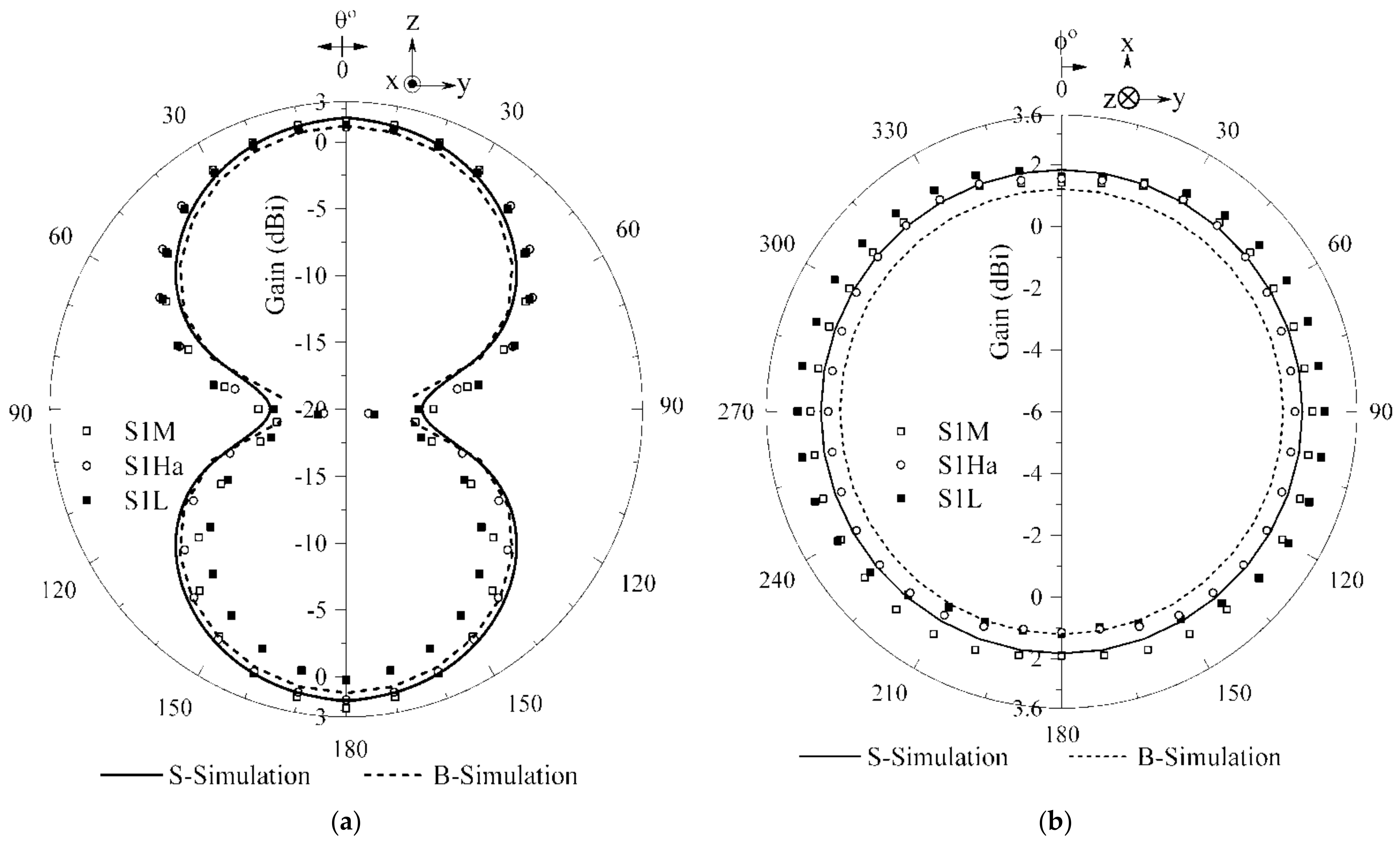
3.5. Radiation Characteristics

The radiation characteristics of the prototypes developed herein were estimated by simulating and measuring the radiation patterns. The measurements were conducted with the antenna radiation measurement system MegiQ RMS-0660 by using the direct method. The uncertainty of the measurement system, as given by the manufacturer, is ±1 dB. A picture of the measurement setup is shown in Figure 8.
Indicative results are shown in Figure 9. The solid (dashed) curve depicts simulated results for an antenna with silver (brass) hybrid sewing thread, whereas the squares and circles correspond to the measured radiation patterns of the prototypes S1Ha, S1L, and S1M, as shown to the inset. The patterns of Figure 9 refer to the resonant frequencies given at the first row of Table 2. Figure 9 demonstrates that the simulated, as well as the measured, radiation patterns exhibit a dipole-like, omnidirectional behavior, as expected. The stitch pattern and the thread material do not seem to affect the radiation characteristics of the antenna significantly. Moreover, a reasonable agreement is observed by comparing the measured with the simulated results.
The measured gain and directivity, as well as the efficiency of several prototypes, are given in Table 4, which indicates that the (measured) efficiency of the proposed antennas varies, roughly, from 40% to 60%, which is a reasonable outcome. The simulation results depicted in the last two columns of Table 4 suggest that the efficiency of the antenna with brass (silver) hybrid thread is 85.2% (96.5%). The latter is greater than the measured values, since real losses may be greater than the simulated ones.

3.6. SAR Εstimation

The SAR has been evaluated since the proposed antenna is intended for wearable applications. The prototype is supposed to operate in proximity to the human chest; the latter has been modeled by a four-layer rectangular model [14], as illustrated in Figure 10. The four tissue layers that constitute the model, as well as their properties, are given in Table 5; the dielectric properties have been calculated by using well known approximations [33,34]. A cotton t-shirt with a of thickness 1.5 mm, εr = 1.6, tanδ = 0, and an 1 mm air gap (εr = 1, tanδ = 0) have been utilized between the antenna and the human skin (Figure 10). Moreover, SAR calculations have been performed by removing the aforementioned air gap in order to consider the worst-case scenario with the antenna mounted directly to the human body. The whole body SAR and the maximum SAR averaged over a volume of 10 g of tissue have been calculated according to the pertinent International Standards [35,36]. The antenna was placed in contact with the cotton t-shirt at the center of the model (Figure 10), and the input power to the antenna was 0.5 W (rms value).
Simulations were performed for the central frequency of the ISM bands, i.e., 868 and 915 MHz; the difference between the obtained SAR values was negligible. The SAR was calculated over 10 g of tissue and, by considering an air gap between the antenna and the human skin, it was found equal to 0.025 W/kg for the whole body, while the peak SAR was 1.86 W/kg. By removing the air gap, the SAR was found to be slightly greater, i.e., 0.029 W/kg (whole body) and 1.91 W/kg (peak). However, all the aforementioned SAR values are below the limits set by the aforementioned International Standards, i.e., 0.08 W/kg (whole body SAR) and 2 W/kg (max SAR over 10 g). However, if a ground plane is inserted between the antenna and the cotton t-shirt, the simulations result in extremely low SAR values: 2.35 × 10⁻⁷ W/kg for the whole body SAR and 1.93 × 10⁻⁶ W/kg for the peak SAR over 10 g tissue.

3.7. Comparisons

Finally, the performance of the proposed antennas is compared to related works. Table 6 summarizes the basic characteristics of several embroidered antennas. Since the prototypes presented herein do not operate in the same frequency band as the ones listed in Table 6, any conclusions extracted may be used with cautiousness. The indication “body” in parenthesis refers to measurements that have been conducted with the antenna mounted on a human body, whereas all other values refer to free space. The −10 dB BW of Refs. [11,14,20,22] has been converted to percentages for the sake of comparison. Table 6 indicates that the proposed antennas exhibit a considerably broader −10 dB BW among similar structures; their efficiency and minimum S11 are both somewhere in the range reported in the literature.

4. Conclusions

Seven prototypes of a wearable, bow-tie antenna, based on the fractal shape of the SPK triangle, have been designed and fabricated in this paper. Specifically, they have been embroidered on a Dupont Nomex meta-aramid fabric by using different conductive sewing threads and/or stitch patterns. Simulations, as well as measurements, have been conducted to evaluate the performance of the prototypes.
The antenna design aimed at covering the unlicensed 863–870 and 902–928 MHz ISM bands—a goal that was reached in most cases examined. Generally, the −10 dB BW of the prototypes embroidered with brass hybrid sewing thread were observed to be greater than the BW of the prototypes fabricated with silver hybrid thread, whereas when the antenna was mounted on a human’s chest, the −10 dB BW was remarkably increased, reaching (and even exceeding) the value of 50% in certain cases. The performance of the proposed antenna was found to depend on its fabrication characteristics and a rather great sensitivity to the dimensions of the prototypes was observed. The antennas were tested under bent conditions that caused a shift of the resonant frequency; this shift was found to be greater for the prototypes embroidered with silver hybrid sewing thread. Moreover, the −10 dB BW exhibited a tendency to increase under bent conditions for all prototypes. The performance of the antenna was also evaluated after up to 10 washing cycles, and it was observed that it may stand such basic rigors.
The measured and simulated radiation patterns have shown that the radiation characteristics of the proposed antennas are not affected significantly by the thread material and/or the stitch pattern. The gain of all prototypes is rather low (less than 3 dB in all cases examined), since the radiation of the proposed antenna is similar to that of an electric dipole. Regarding the efficiency of the prototypes, it was found to be roughly between 40 and 60%. Finally, the SAR values that were calculated by using a rectangular layered model of the human chest do not exceed the limits suggested by International Standards for all cases examined.

Author Contributions

Conceptualization, M.P., R.S., T.N.K. and I.O.V.; methodology, M.P., R.S., T.N.K. and I.O.V.; software, T.N.K., C.D.N. and A.T.B.; validation, T.N.K., C.D.N., A.T.B. and I.O.V.; formal analysis, T.N.K., M.P.I. and I.O.V.; measurements, T.N.K. and M.P.; investigation, T.N.K., M.P., M.P.I. and I.O.V.; resources, M.P., C.D.N., T.N.K. and I.O.V.; data curation, C.D.N. and A.T.B.; writing—original draft preparation, T.N.K., M.P.I. and I.O.V.; writing—review and editing, M.P.I. and I.O.V.; visualization, T.N.K. and I.O.V.; supervision, I.O.V.; project administration, I.O.V.; funding acquisition, T.N.K., M.P.I., C.D.N. and I.O.V. All authors have read and agreed to the published version of the manuscript.

Funding

This research received no external funding.

Data Availability Statement

The data presented in this study are available on request from the corresponding author. The data are not publicly available due to privacy restrictions.

Acknowledgments

The research work of T.N. Kapetanakis, C.D. Nikolopoulos and I.O. Vardiambasis is co-financed by Greece and the European Union (European Social Fund—ESF) through the Operational Program “Human Resources Development, Education and Lifelong Learning 2014–2020” in the context of the project “Smart microwave nanomaterial structures with applications in bodycentric communications and the Internet of Things (MIS 5048187)”.

Conflicts of Interest

The authors declare no conflict of interest.

References

  1. Loss, C.; Gonçalves, R.; Lopes, C.; Pinho, P.; Salvado, R. Smart coat with a fully-embedded textile antenna for IoT applications. Sensors 2016, 16, 938. [Google Scholar] [CrossRef]
  2. Tsolis, A.; Whittow, W.G.; Alexandridis, A.A.; Vardaxoglou, J.C. Embroidery and related manufacturing techniques for wearable antennas: Challenges and opportunities. Electronics 2014, 3, 314–338. [Google Scholar] [CrossRef] [Green Version]
  3. Kiourti, A.; Volakis, J.L. Colorful textile antennas integrated into embroidered logos. J. Sens. Actuator Netw. 2015, 4, 371–377. [Google Scholar] [CrossRef]
  4. Lilja, J.; Salonen, P.; Kaija, T.; de Maagt, P. Design and manufacturing of robust textile antennas for harsh environments. IEEE Trans. Antennas Propag. 2012, 60, 4130–4140. [Google Scholar] [CrossRef]
  5. Zhang, S.; Whittow, W.; Seager, R.; Chauraya, A.; Vardaxoglou, Y. Non-uniform mesh for embroidered microstrip antennas. IET Microw. Antennas Propag. 2017, 11, 1086–1091. [Google Scholar] [CrossRef] [Green Version]
  6. Seager, R.; Zhang, S.; Chauraya, A.; Whittow, W.; Vardaxoglou, Y.; Acti, T.; Dias, T. Effect of the fabrication parameters on the performance of embroidered antennas. IET Microw. Antennas Propag. 2013, 7, 1174–1181. [Google Scholar] [CrossRef] [Green Version]
  7. Zhong, J.; Kiourti, A.; Sebastian, T.; Bayram, Y.; Volakis, J.L. Conformal load-bearing spiral antenna on conductive textile threads. IEEE Antennas Wirel. Propag. Lett. 2017, 16, 230–233. [Google Scholar] [CrossRef]
  8. Paul, D.L.; Giddens, H.; Paterson, M.G.; Hilton, G.S.; McGeehan, J.P. Impact of body and clothing on a wearable textile dual band antenna at digital television and wireless communications bands. IEEE Trans. Antennas Propag. 2013, 61, 2188–2194. [Google Scholar] [CrossRef]
  9. Wang, Z.; Lee, L.Z.; Psychoudakis, D.; Volakis, J.L. Embroidered multiband body-worn antenna for GSM/PCS/WLAN communications. IEEE Trans. Antennas Propag. 2014, 62, 3321–3329. [Google Scholar] [CrossRef]
  10. Zhang, S.; Paraskevopoulos, A.; Luxey, C.; Pinto, J.; Whittow, W. Broad-band embroidered spiral antenna for off-body communications. IET Microw. Antennas Propag. 2016, 10, 1395–1401. [Google Scholar] [CrossRef] [Green Version]
  11. Paraskevopoulos, A.; de Sousa Fonseca, D.; Seager, R.D.; Whittow, W.; Alexandridis, A.A. Higher-mode textile patch antenna with embroidered vias for on-body communication. IET Microw. Antennas Propag. 2016, 10, 802–807. [Google Scholar] [CrossRef] [Green Version]
  12. Almohammed, B.; Ismail, A.; Sali, A. Electro-textile wearable antennas in wireless body area networks: Materials, antenna design, manufacturing techniques, and human body consideration—A review. Text. Res. J. 2021, 91, 646–663. [Google Scholar] [CrossRef]
  13. Gil, I.; Fernadez-Garcia, R. Wearable PIFA antenna implemented on jean substrate for wireless body area network. J. Electromagn. Waves Appl. 2017, 31, 1194–1204. [Google Scholar] [CrossRef]
  14. Anbalagan, A.; Sundarsingh, E.F.; Ramalingam, V.S. Design and experimental evaluation of a novel on-body textile antenna for unicat applications. Microw. Opt. Technol. Lett. 2020, 62, 789–799. [Google Scholar] [CrossRef]
  15. Mao, C.X.; Vital, D.; Werner, D.H.; Wu, Y.; Bhardwai, S. Dual-polarized embroidered textile armband antenna array with omnidirectional radiation for on-/off-body wearable applications. IEEE Trans. Antennas Propag. 2020, 68, 2575–2584. [Google Scholar] [CrossRef]
  16. Kioski, K.; Sydanheimo, L.; Rahmat-Samii, Y.; Ukkonen, L. Fundamental characteristics of electro-textiles in wearable UHF RFID patch antennas for body-centric sensing systems. IEEE Trans. Antennas Propag. 2014, 62, 6454–6462. [Google Scholar] [CrossRef]
  17. Jiang, Y.; Xu, L.; Pan, K.; Leng, T.; Li, Y.; Danoon, L.; Hu, Z. e-Textile embroidered wearable near-field communication RFID antennas. IET Microw. Antennas Propag. 2019, 13, 99–104. [Google Scholar] [CrossRef] [Green Version]
  18. Abbas, B.; Khamas, S.K.; Ismail, A.; Sali, A. Fully embroidery designed electro-textile wearable tag antenna for WBAN application. Sensors 2019, 19, 2470. [Google Scholar] [CrossRef] [Green Version]
  19. Kiourti, A.; Lee, C.; Volakis, J.L. Fabrication of textile antennas and circuits with 0.1mm precision. IEEE Antennas Wirel. Propag. Lett. 2016, 15, 151–153. [Google Scholar] [CrossRef]
  20. Liu, F.X.; Xu, Z.; Ranasinghe, D.C.; Fumeaux, C. Textile folded half-mode substrate-integrated cavity antenna. IEEE Antennas Wirel. Propag. Lett. 2016, 15, 1693–1697. [Google Scholar] [CrossRef]
  21. Alonso-Gonzalez, L.; Ver-Hoeye, S.; Fernadez-Garcia, M.; Vazquez-Antuna, C.; Las-Heras Andres, F. On the development of a novel mixed embroidered-woven slot antenna for wireless applications. IEEE Access 2019, 7, 9476–9489. [Google Scholar] [CrossRef]
  22. Moradi, B.; Fernandez-Garcia, R.; Gil, I. Wearable high-performance meander ring dipole antenna for electronic-textile applications. J. Text. Instit. 2020, 111, 178–182. [Google Scholar] [CrossRef]
  23. Zhong, J.; Lee, C.W.; Papantonis, D.; Kiourti, A.; Volakis, J.L. Body-worn 30:1 bandwidth tightly coupled dipole array on conductive textiles. IEEE Antennas Wirel. Propag. Lett. 2018, 7, 723–726. [Google Scholar] [CrossRef]
  24. Waqas, M.; Ahmed, Z.; Ihsan, M.B. Multiband Sierpinski fractal antenna. In Proceedings of the 2009 IEEE 13th International Multitopic Conference, Islamabad, Pakistan, 14–15 December 2009. [Google Scholar]
  25. Chowdary, P.S.R.; Prasad, A.M.; Rao, P.M.; Anguera, J. Design and performance study of Sierpinski fractal based patch antennas for multiband and miniaturization characteristics. Wirel. Pers. Commun. 2015, 83, 1713–1730. [Google Scholar] [CrossRef]
  26. Figueroa-Torres, C.A.; Medina-Monroy, J.L.; Lobato-Morales, H.; Chaves-Perez, R.A.; Calvillo-Tellez, A. A novel fractal antenna based on the Sierpinski structure for super wide-band applications. Microw. Opt. Technol. Lett. 2017, 59, 1148–1153. [Google Scholar] [CrossRef]
  27. Baliarda, C.P.; Romeu, J.; Pous, R.; Cardama, A. On the behavior of the Sierpinski multiband fractal antenna. IEEE Trans. Antennas Propag. 1998, 46, 517–524. [Google Scholar] [CrossRef] [Green Version]
  28. Kaur, J.; Singh, S.; Kansal, A. Multiband behaviour of Sierpinski fractal antenna. Res. J. Inf. Technol. 2011, 3, 3–43. [Google Scholar] [CrossRef] [Green Version]
  29. Pavec, M.; Kapetanakis, T.N.; Ioannidou, M.P.; Nikolopoulos, C.D.; Baklezos, A.T.; Soukup, R.; Blecha, T.; Hamacek, A.; Vardiambasis, I.O. Implementation of an all-textile bow-tie antenna for the 868 MHz ISM band. In Proceedings of the 2020 International Symposium on Electromagnetic Compatibility (EMC Europe 2020), Rome, Italy, 23–25 September 2020. [Google Scholar]
  30. Pavec, M.; Navratil, J.; Soukup, R.; Hamacek, A. A bowtie antenna prepared by aerosol jet and embroidering technology. In Proceedings of the 41st International Spring Seminar on Electronics Technology (ISSE), Zlatibor, Serbia, 16–20 May 2018; pp. 1–4. [Google Scholar]
  31. Blecha, T.; Hamacek, A.; Hotmar, M.; Kaspar, P.; Pilikova, M.; Reboun, J.; Soukup, R.; Svecar, F.; Tichy, M. Sewing thread for integration of electronic elements into fabrics. Patent CZ28603 U1, 18 May 2015. [Google Scholar]
  32. Balanis, C.A. Antenna Theory: Analysis and Design, 4th ed.; Wiley: Hoboken, NJ, USA, 2016. [Google Scholar]
  33. Gabriel, S.; Lau, R.W.; Gabriel, C. The dielectric properties of biological tissues: II. Measurements in the frequency range 10 Hz to 20 GHz. Phys. Med. Biol. 1996, 41, 2251–2269. [Google Scholar] [CrossRef] [PubMed] [Green Version]
  34. Andreuccetti, D.; Fossi, R.; Petrucci, C. An Internet Resource for the Calculation of the Dielectric Properties of Body Tissues in the Frequency Range 10 Hz–100 GHz; IFAC-CNR: Florence, Italy, 1997. [Google Scholar]
  35. IEC/IEEE International Standard. Determining the Peak Spatial-Average Specific Absorption Rate (SAR) in the Human Body from Wireless Communications Devices, 30 MHz to 6 GHz—Part 1: General Requirements for Using the Finite-Difference Time-Domain (FDTD) Method for SAR Calculations; IEC/IEEE 62704-1:2017; IEEE: Piscataway, NJ, USA, 2017; pp. 1–86. [Google Scholar]
  36. IEEE-SA Standards Board. IEEE Recommended Practice for Measurements and Computations of Radio Frequency Electromagnetic Fields with Respect to Human Exposure to Such Fields, 100 kHz 300 GHz; IEEE Std C95.3-2002 (Revision of IEEE Std C95.3-1991), no. 4; IEEE: Piscataway, NJ, USA, 2002; pp. 1–126. [Google Scholar]
Figure 1. Geometrical sketch of the proposed bow-tie antenna.
Electronics 10 01983 g001
Figure 2. Picture of the bow-tie antenna prototype “S1Ha”.
Electronics 10 01983 g002
Figure 3. Schematic illustration of the bow-tie antenna structure.
Electronics 10 01983 g003
Figure 4. Measured magnitude of S11 of the bow-tie antenna versus frequency: (a) S1Ha (silver hybrid thread) and (b) B1Ha (brass hybrid thread) prototype. The effect of human body presence and bending conditions on bow-tie antenna’s S11 is exhibited: the dashed/dotted curves refer to concave/convex bending of the antenna mounted on human body (measurements), while the black solid and the blue marked curves correspond to the planar antenna in free space (measurements and simulations, respectively).
Electronics 10 01983 g004
Figure 5. Bent conditions: (a) Concave-x, (b) convex-x, (c) concave-y and (d) convex-y.
Electronics 10 01983 g005
Figure 6. Measured magnitude of S11 of the bow-tie antenna versus frequency. The antenna is bent, as shown in Figure 5c. (a) S1Ha and (b) B1Ha prototype.
Electronics 10 01983 g006
Figure 7. Deviation (%) of fc, under various bent conditions, for the tube diameters as shown in the vertical axis. S1Ha and B1Ha prototypes are considered.
Electronics 10 01983 g007
Figure 8. Measurement setup of the radiation characteristics.
Electronics 10 01983 g008
Figure 9. Simulated (solid and dashed curves) and measured (squares and circles for the prototypes shown in the inset) free-space radiation patterns: (a) E-plane (θ-plane or elevation plane) and (b) H-plane (φ-plane or azimuthal plane).
Electronics 10 01983 g009
Figure 10. Layered human’s chest model (L and W are taken equal to 210 and 130 mm, respectively, whereas hi, i = 1,…, 4, are given in Table 5).
Electronics 10 01983 g010
Table 1. Geometrical and fabrication characteristics of the antenna prototypes.
Antenna PrototypeS1LS1MS1HaS1HbS2HB1HaB1HbNominalSimulated
Thread materialSSSSSBB-S/B
Stitch patternLowMediumHighHighHighHighHigh-High
Conductive side1111211-1
L0 (mm)48.0347.7848.5444.5748.2445.9149.775048
L1 (mm)22.2921.9121.4119.9822.2221.3623.892324
L2 (mm)10.379.749.129.109.999.2310.261012
wg (mm)2.792.813.033.883.071.903.132.12.2
θt (deg)60.6661.5358.2756.3858.3361.9862.446060
Table 2. Measured and simulated characteristics of the antenna prototypes in free space.
Antenna PrototypeS1LS1MS1HaS1HbS2HB1HaB1HbS-SimulatedB-Simulated
fc (MHz)963.2949.1957.2975970.2961.4860918.3912.4
S11 (dB) @ fc−18.7−15.4−16.1−16.0−21.9−22.7−23−14.5−15.4
VSWR @ fc1.261.411.371.351.201.171.161.461.41
f1 (MHz)868861841900910800740863855
f2 (MHz)10279981007101910481028977982974
−10 dB BW (MHz)159137166119138228237119119
−10 dB BW (%)16.514.417.312.214.223.727.612.913.1
Table 3. Characteristics of the prototype B1Hb, after several washing cycles.
Washing Cycle0123510
fc (MHz)860842845892903911
S11 (dB) @ fc−23−19−16−16−18−15
VSWR @ fc1.161.271.381.381.301.44
f1 (MHz)740735730719731840
f2 (MHz)977977946977979987
−10 dB BW (MHz)237242216258248147
Table 4. Gain, directivity, and efficiency of several prototypes.
Antenna PrototypeS1MS1HaS1LS2HB1HaS-SimulationB-Simulation
Gain (dBi)2.371.922.583.511.21.831.21
Directivity (dB)6.236.026.025.685.441.991.90
Efficiency41.1%38.9%45.2%60.7%37.7%96,5%85,2%
Table 5. Tissue properties and thicknesses used for SAR estimation.
Tissue Typeσ (S/m)εrtanδDensity (kg/m3)Thickness (mm)
Dry skin0.8641.60.42611001.5
Fat0.055.50.19090013
Muscle0.9355.10.350108020
Cortical bone0.1412.50.23120003.5
Table 6. Comparison of the proposed antennas with previous works.
ReferenceAntennafc−10 dB BWmin S11
(dB)
Gain (dBi)Efficiency (%)DimensionsSAR over 10 g (W/kg)
[3]Logo shaped2.4 GHz-−173 -37.4 × 24.4 mm2-
[11]Textile patch2.4 GHz
(2.44 body)
6.3%−23.1
(−22 body)
155
(40 body)
5 × 5 cm2-
[13]Planar inverted-F PIFA BT-JGJ2.42 GHz
(2.32 body)
6.2%−112.49
(1.98 body)
82.2
(29.1 body)
50 × 16 mm20.97
(peak value)
[14]4-layer patch2.45 GHz20.4%−287.1167.0358 × 63 mm20.01
[18]Textile tag915 MHz-−24−1 (body)-72 × 20 mm2-
[20]Folded half-mode cavity2.425 GHz4.1%−287.18582.8 × 41.4 mm2-
[22]Meander ring dipole325 MHz6.2%−181.549342 mm (diameter)-
This workSPK fractal bow-tie silver thread-S1Ha957.2 MHz17.3%
(50.7% body)
−16.11.923988 × 50 mm20.025
(with air gap)
0.029
(without air gap)
SPK fractal bow-tie brass thread-B1Ha961.4 MHz23.7%
(47.4% body)
−22.71.238
Publisher’s Note: MDPI stays neutral with regard to jurisdictional claims in published maps and institutional affiliations.

