Article

UWB Dual-Band-Notched Lanky-Leaf-Shaped Antenna with Loaded Half-Square-Like Slots for Communication System

1
College of Electronic and Electrical Engineering, Henan Normal University, Xinxiang 453600, China
2
Henan Key Laboratory of Optoelectronic Sensing Integrated Application, Henan Normal University, Xinxiang 453600, China
3
Academician Workstation of Electromagnetic Wave Engineering of Henan Province, Henan Normal University, Xinxiang 453600, China
*
Author to whom correspondence should be addressed.
Electronics 2021, 10(16), 1991; https://doi.org/10.3390/electronics10161991
Submission received: 13 July 2021 / Revised: 11 August 2021 / Accepted: 16 August 2021 / Published: 18 August 2021
(This article belongs to the Section Microwave and Wireless Communications)

Abstract

:
A novel printed compact single-layer dual-band-notched antenna for the use of ultra-wide band (UWB) is proposed in this paper, and one lanky-leaf-like structure with a coplanar waveguide (CPW) feed is designed as the radiated element for a large operating bandwidth. To realize the dual-band-notched characteristics of microwave access (WiMAX) and wireless local area networks (WLAN), two half-square-like slots are etched on the metallic surface. The fabricated prototype of this proposed antenna has a compact size of 27 × 32 mm2 and operates at 2.8 GHz to 10 GHz, excepting for rejection bands at 3.06–3.83 GHz and 5.05–5.96 GHz. Nearly omnidirectional radiation patterns are obtained in the working band. Furthermore, one conformal design on cylinder and transfer characteristics are made to validate its potential application. These findings indicate that this antenna can be taken as a promising option for use in the UWB communication field.

1. Introduction

The permission of the 3.1–10.6 GHz frequency band for commercial use has brought about an upsurge in the ultra-wide-band (UWB) system. As one of the most critical parts in the UWB system, UWB antenna has been researched and manufactured [1,2,3]. Among these attractive antennas, monopole is considered one prospective technology for current wireless application on account of its small size, easy manufacture, and convenience in integrating with miniaturizing RF front ends.
Nowadays, with the commercialization of 5G networks and the deployment of 6G networks, the volume of a mobile device is made lighter and tinier, and miniaturizing UWB antennas that can cover the whole work frequency has become an indispensable technique during communication design. Nevertheless, a few already-used narrow-band communication systems, such as microwave access (WiMAX) at 3.3–3.8 GHz and wireless local area networks (WLAN) at 5.15–5.825 GHz, may induce possible electromagnetic coupling with these UWB applications [4]. To solve this problem, many researchers have raised lots of band-notched methods in UWB antennas. For example, [5,6] achieved notched characteristics by etching slots in antenna patches and [7] used a hook-shaped defected ground structure (DGS), and [8] achieved triple-band-notched characteristics by introducing a printed capacitance loaded loop (CLL) resonator beside the feed line, but the cost was high and not favorable for practical applications. In addition, to realize the rejection band, several designed configurations have been presented by using a planar monopole together with a modified radiator and ground plane, which can include triple notch frequencies [9,10,11,12], dual notch frequencies [13,14], and a single notch frequency [15,16]. Moreover, the notch frequencies over the band were obtained through split-ring resonators connected to the feed line or plural embedded slots on the patch [17,18]. Normally, the band-notched function can be realized by adopting half of the guided wavelength with the desired notch frequency point as the slot length [19].
Generally, the size of existing UWB antennas mentioned above is expected to be further reduced, but the small size cannot maintain more notched-band characteristics, for example, a small-size slot antenna with a large bandwidth is achieved by etching two slots on the ground plane, but only single-notched-band characteristics at 5–6 GHz can be realized in [20]. Although [21,22] have a large antenna bandwidth, the size is too small to only realize band-notched characteristics. The antennas presented in [23,24] have high gain and double-notched-band characteristics, nonetheless, with a larger size and more expensive substrate. UWB antennas with notched-band characteristics have attracted increasing attention in the academia and industry, but they usually possess their own drawbacks in relative terms. Thus, exploring antennas with superior capability and limited size is an important work.
In this paper, a lanky-leaf-shaped antenna with dual-band-notched characteristics is proposed. The UWB characteristics at an operating band of 2.8–10 GHz are achieved by constructing a lanky-leaf-like radiating patch, and the dual-band-notched characteristics in the WiMAX and WLAN can be obtained through etching two different lengths of half-square-like slots on the radiation patch. In addition, the conformal capability of the proposed antenna in practical applications is also investigated. Finally, one prototype antenna is fabricated, and its performances in bandwidth, gain, and radiation pattern are practically measured.

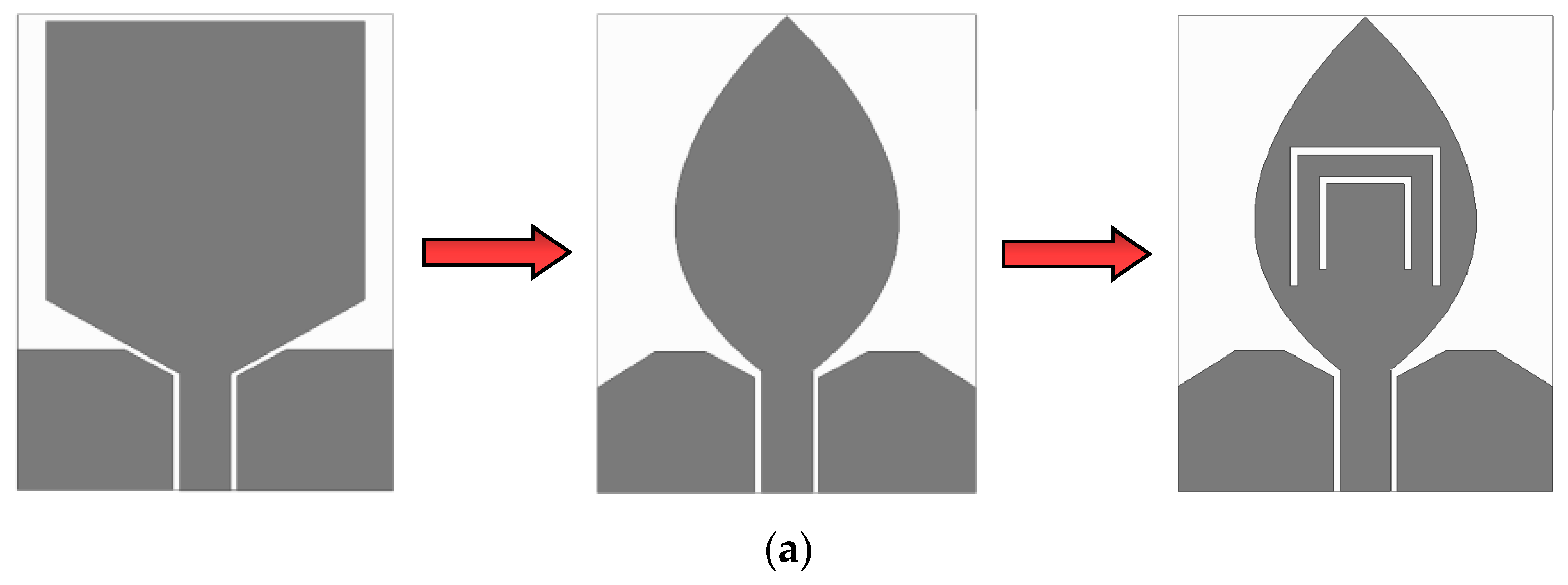
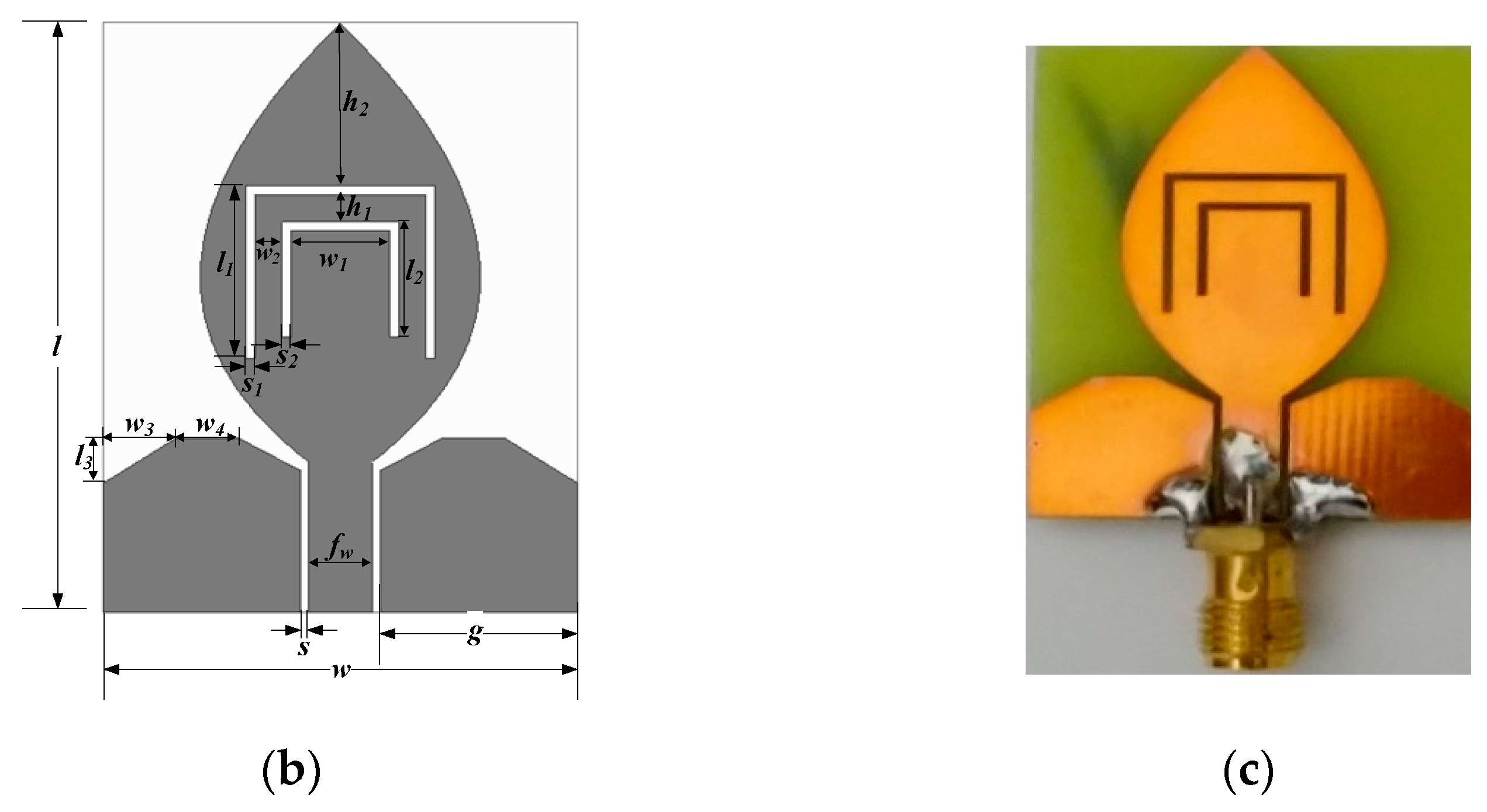
2. Slot Antenna Model

In the beginning, a waveguide-fed rectangular patch antenna is designed after reviewing the commercially available literature. Based on the purposes of extending the bandwidth and eliminating the current discontinuity points in the edge current path, an arc structure is loaded on the edge of the rectangular patch. Considering the requirements of specific application scenarios, the notched characteristics at 3.5 GHz and 5.5 GHz are achieved by etching two half-square-like slots on the main radiating patch. Thus, the final structure of the antenna can be obtained, and the evolutionary process is shown in Figure 1a. Figure 1b demonstrates the geometry of the proposed antenna, and the actual antenna prototype is shown in Figure 1c. The novel antenna is fabricated on a low-cost FR4 substrate with a thickness of 1 mm and a relative dielectric constant of 4.4. The optimum dimensions of a dual-band-notched antenna are shown in Table 1.
The radiation characteristics of the designed lanky-leaf patch are related to the length and width of the shape. Formula (1) depicts the arc structure of the lanky-leaf patch. In addition, the notch structure is used to achieve the notched-band feature, and it can be computed as Formula (2).
x ( k ) = 25.4 e 1.8 k cos ( π k ) y ( k ) = 7.7 sin ( 2 π k )       0.5   <   k   <   0.5
L = c 2 f ε r + 1 2
where f is the center frequency of the notched band, L refers to the length of the notch structures, and c represents the speed of light in vacuum. εr is the relative dielectric constant of the dielectric material. The calculated lengths of half-square-like slots etched on the radiating patch are 27.1 mm and 16.7 mm at notched bands of 3.5 GHz and 5.5 GHz. In practical manufacture, the actual lengths are 27.8 mm and 17.5 mm, respectively.
The current distributions of the designed antenna at the central frequency of two notched bands are depicted in Figure 2. It can be distinctly found that the surface current mainly concentrates on the external half-square-like slot for the lower-notched band. On the contrary, the stronger surface current focuses on the inner half-square-like slot for the higher-notched band. The observed phenomenon is well consistent with the original design points.
Based on aforementioned analyses, in the following, variation curves of VSWR with some critical parameters of the half-square-like slot are simulated. Each time only one parameter changes, while the other parameters of the antenna remain constant. Figure 3a shows VSWR curves with external loaded slot lengths l1 of 8 mm, 9 mm, and 10 mm. It can be seen that the center frequencies of the first notched band are shifted towards the lower frequency with an increasing length. This behavior is because the increase in effective length of a half-square-like slot makes the notch center frequencies exhibit a shrinking trend. The length of the loaded inner slot of l2 is studied in Figure 3b. With a transition from 5.5 mm to 6.2 mm, the higher-notched band at 5.5 GHz transfers to a lower frequency, and there is nearly no change to the notched characteristics. Figure 4 shows the effect of the width for the etched half-square-like slot on the VSWR. As the width of the external and inner loaded slots is enhanced, there is not much change to both notched bands.
Since the interval between two half-square-like slots is small, the electromagnetic coupling between them may be strong. Thus, the influence of distance between two etched slots on the notched properties has also been investigated, and the corresponding VSWR is drawn in Figure 5. As shown in Figure 5a, the notched characteristics of both bands do not exhibit much change to alter the interval in the horizontal direction. However, the decreasing vertical interval can lead to the second notched band at 5.5 GHz shifting to a higher trend (see Figure 5b). Meanwhile, the bandwidth of the second resonant pattern can also be increased. However, the lower-notched band at 3.5 GHz seems almost unaffected.

3. Results and Discussion

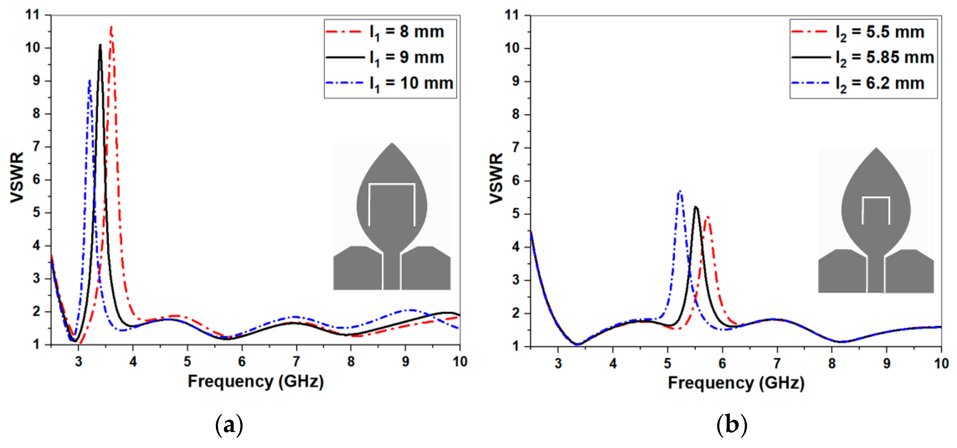
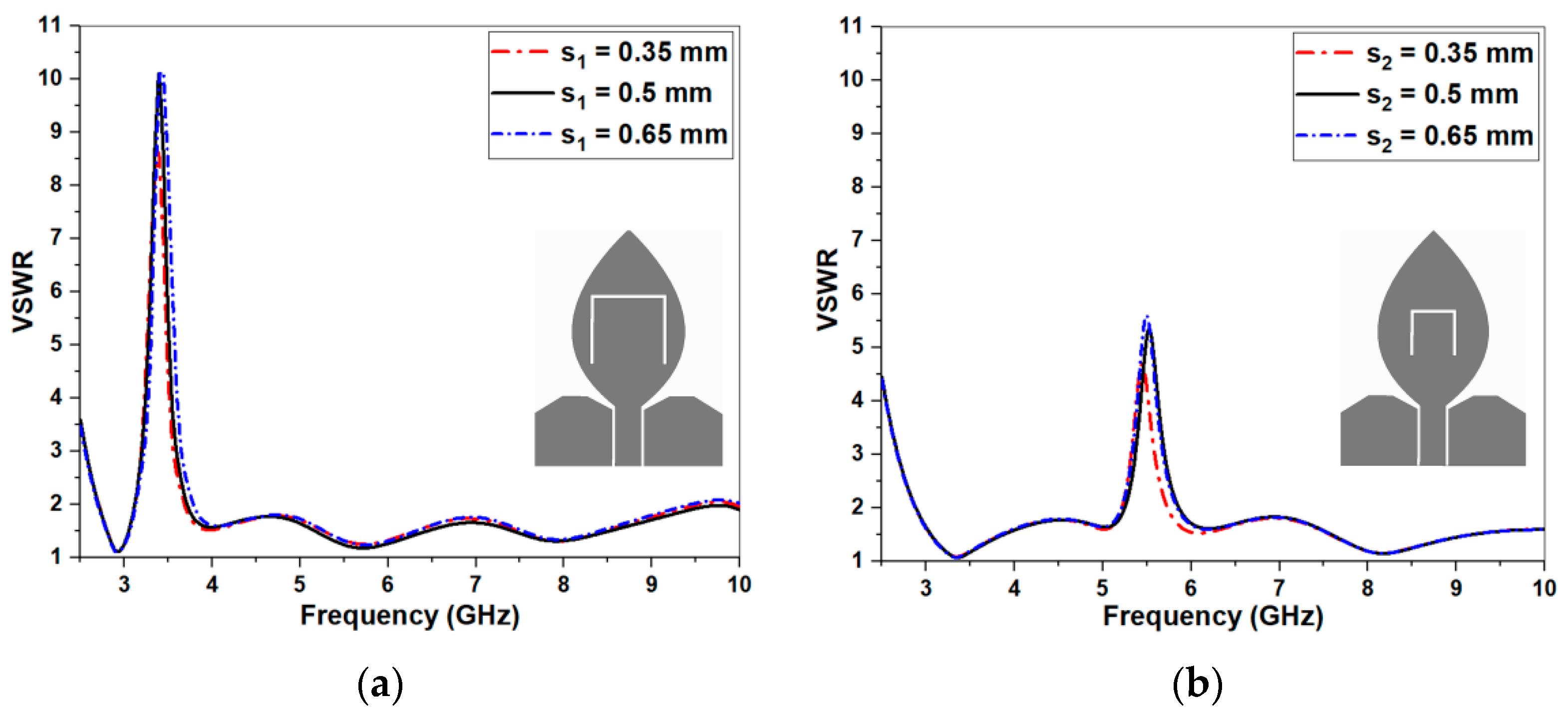
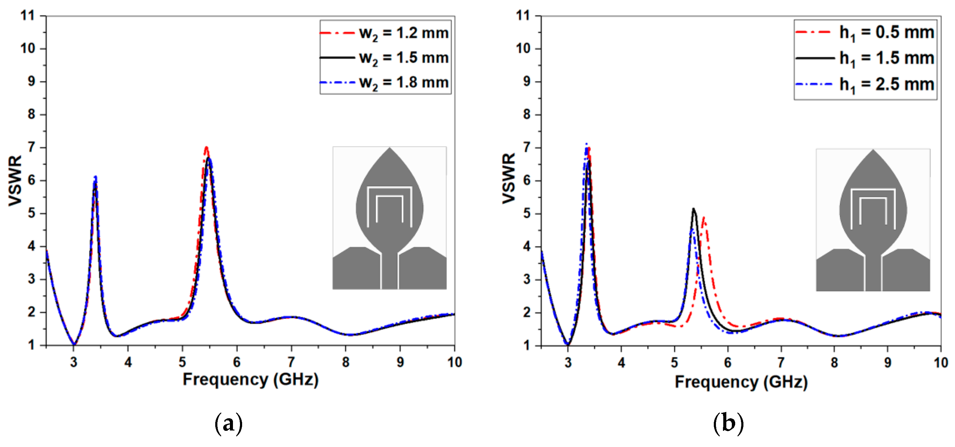
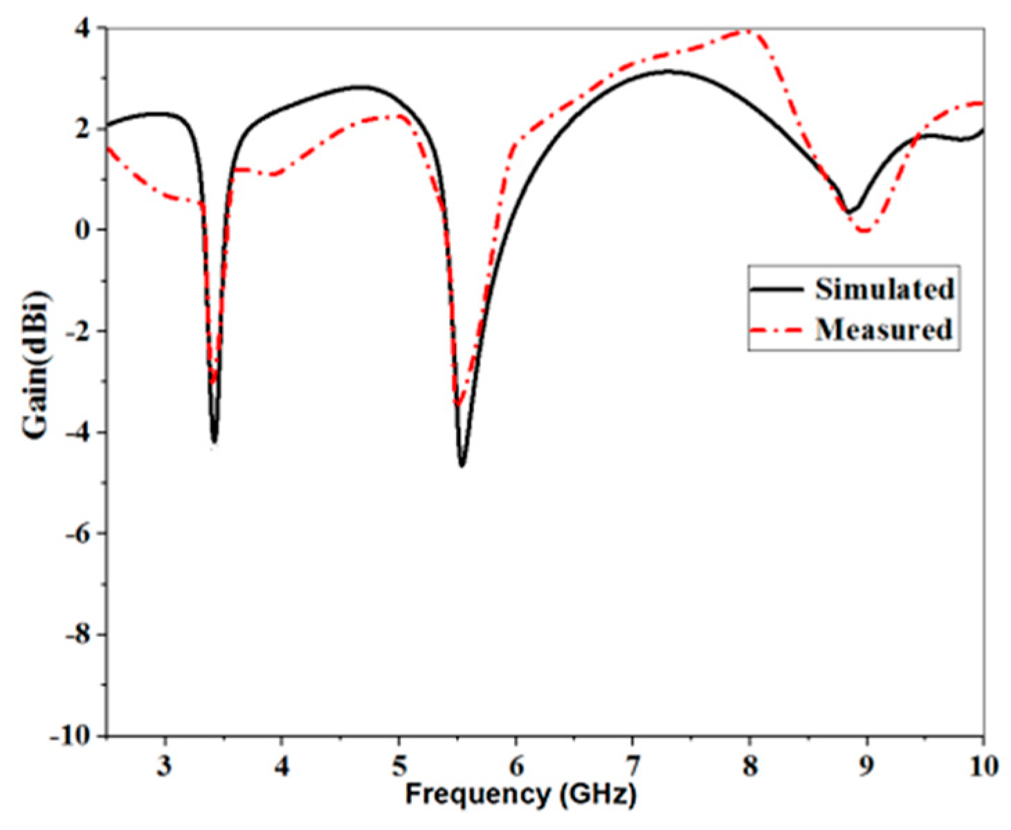
3.1. Simulation and Measurement Results

The proposed antenna is designed and optimized through the software of Ansoft HFSS and CST, and relevant performances, such as return loss, radiation patterns, and gain, are measured in an anechoic chamber. Figure 6 displays the measured and simulated VSWR of the antenna. The impedance bandwidth with VSWR < 2 is between 2.8 GHz and 10 GHz, apart from notch bands of 3.06–3.83 GHz and 5.05–5.96 GHz. The peak values of VSWR for the center frequencies of two rejection bands (3.52 GHz and 5.57 GHz) are 6 and 5, which means that almost all power is reflected at the feeding port and no energy can be transferred to the antenna. Moreover, the simulation and measurement agree well with each other. The little diversity between them is induced by the insertion of an SMA connector and construction tolerance.
Next, normalized radiation patterns of 4 GHz, 7 GHz, and 10 GHz are exhibited in Figure 7. The omni characteristics can be found among all the working frequencies. Figure 8 shows the peak gain of the dual-band-notched antenna. We know that the measured peak gain can change between 1.7 dBi and 3.9 dBi among working bands. Moreover, the gain demonstrates a sharp downtrend at the two rejection bands, indicating poor radiation capability and good rejection characteristics. The simulation has good consistency with the measured data, which means good radiation properties in practical applications.

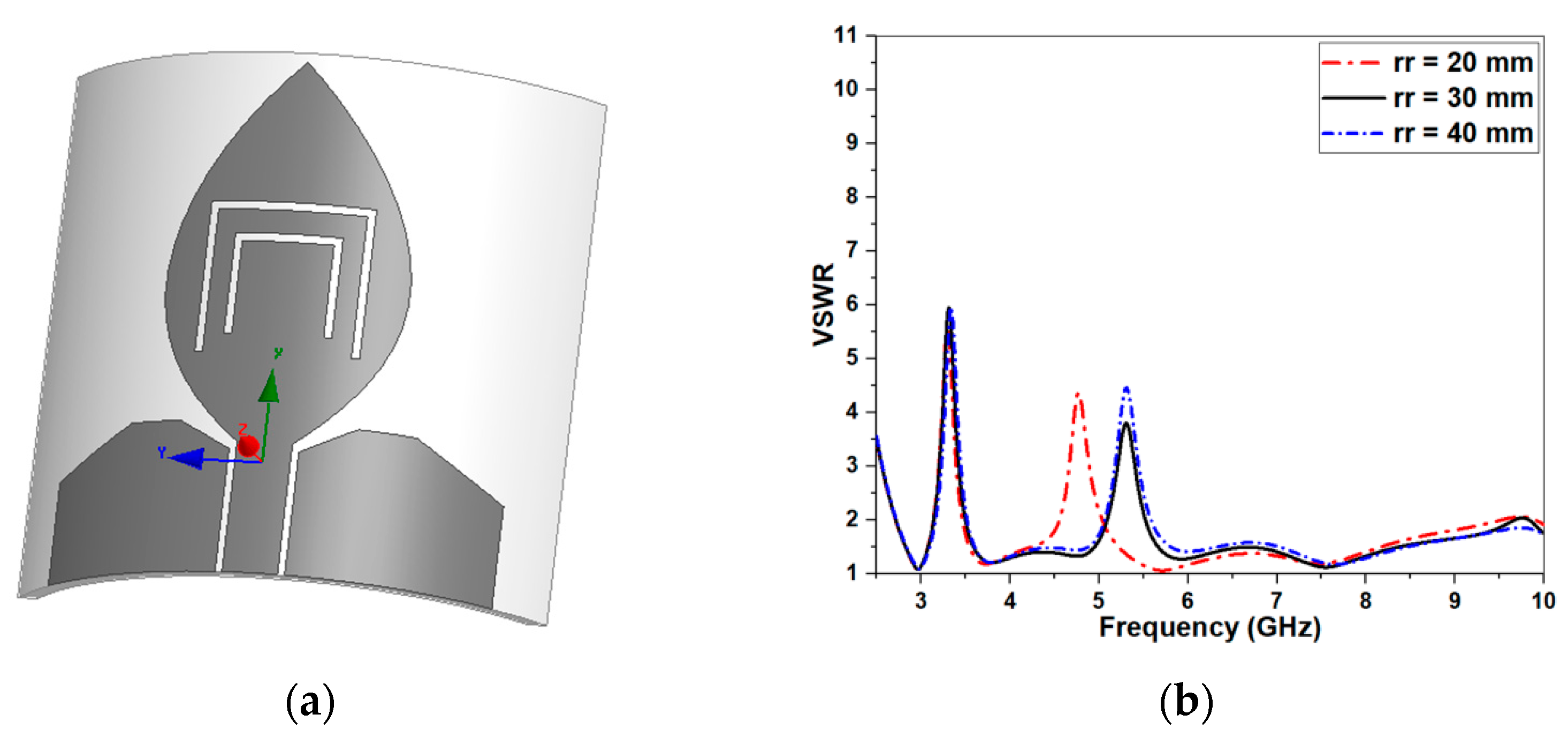
3.2. Future Application Performance Evaluation

In general, miniaturized antennas are used together with other devices in practical applications, and when applied for some special-purpose designs, it may be necessary to integrate the antenna on an irregular plane, resulting in the radiation performance of the antenna being changed. Thus, in the following, a series of studies on the conformal properties of the antenna were carried out, in which the radius rr of the projected cylinder was regulated to control the degree of deformation of the antenna model (see Figure 9a). To check the sensitivity of the antenna performance on the conformal cylinder, some results are compared in Figure 9b. It can be observed that there are nearly no changes at a lower-notched band, but the higher-notched-band shifts to lower frequencies with the decrease in radius rr. When the radius of the cylinder is small, the projection processing can make more deformations on the antenna surface, and a small extension occurs at the conductor and etched slots, especially for the higher frequency. Thus, to consider the conformal application, the contraction–expansion factor should be considered at a higher-notched band.
For many UWB communication systems, the antenna performance in time domain is very important, which can largely affect the signal quality in the transceiver. To understand the ability of the proposed antenna, we placed a pair of antennas facing each other at a distance of 500 mm with the same height (see Figure 10a), and one narrow Gaussian pulse was set as an excited source in the simulation with an operating bandwidth from DC to 10 GHz. The final received signal shown in Figure 10b has a good radiated signal with a small oscillated ringing.
Furthermore, Table 2 lists a comparison of the presented antenna with other existing studies. Although the fractional bandwidth of the proposed antenna is lower than that in [22,24], it is observed that the physical and electrical dimensions of the proposed antenna are smaller than those reported by the authors and [22] only has one notched band. The size and fractional bandwidth of the proposed antenna in this work are comparable to those of the reported work in [21], but they can realize the dual-band-notched characteristics, as shown in Table 2. Additionally, [23,25] have a smaller fractional bandwidth and expensive dielectric material together with a larger size compared with this work. It can be seen in Table 2 that the proposed antenna has advantages, such as suitable bandwidth, dual-band-notched characteristics, small dimensions, and low cost.

4. Conclusions

A small UWB antenna with double-notched characteristics is presented and constructed in this paper. This antenna has a simple structure and compact size of 27 × 32 mm2, which is convenient for integrating with a miniaturizing facility. The simulation and measurement agree well with each other, and the whole bandwidth can cover 2.8 to 10 GHz. To avoid a conflict with WiMAX and WLAN systems, two band rejection structures are selected to generate sharp rejection, and the return losses close to 3.4 and 5.5 GHz are −2.7 and −2.8 dBi, respectively. In addition, good impedance matching, omni radiation patterns, and smooth gain covering the whole pass band can be observed in the test. Conformal feasibility and transfer characteristics are also studied to validate the antenna’s potential application. Thus, this antenna can be a promising candidate for use in UWB communication systems.

Author Contributions

Conceptualization, X.-P.L. and G.X.; methodology, X.-P.L. and M.-R.M.; software, X.-P.L.; validation, X.-P.L., G.X. and M.-R.M.; formal analysis, C.-J.D.; investigation, X.-P.L. and G.X.; data curation, C.-J.D.; writing—original draft preparation, G.X.; writing—review and editing, X.-P.L.; supervision, X.-P.L. All authors have read and agreed to the published version of the manuscript.

Funding

This research received no external funding.

Conflicts of Interest

The authors declare no conflicts of interest.

References

  1. Darvish, A.; Zakeri, B.; Fallah, P. 50–100 Ohms 130 MHz–5 GHz resistively loaded bow-tie antenna for efficient UWB mono-pulse radiation. AEU Int. J. Electron. Commun. 2021, 138, 153807. [Google Scholar] [CrossRef]
  2. Serhir, M.; Lesselier, D. Wideband reflector-backed folded bowtie antenna for ground penetrating radar. IEEE Trans. Antennas Propag. 2018, 66, 1056–1063. [Google Scholar] [CrossRef]
  3. Liu, H.W.; Ku, C.H.; Wang, T.S.; Yang, C.F. Compact monopole antenna with band-notched characteristic for UWB applications. IEEE Antennas Wirel. Propag. Lett. 2010, 9, 397–400. [Google Scholar] [CrossRef]
  4. Federal Communications Commission. Federal Communications Commission Revision of Part 15 of the Commision’s Rules Regarding Ultra-Wideband Transmission System from 3.1 to 10.6 GHz; ET-Docket: Washington, DC, USA, 2002.
  5. Fan, F.; Yan, Z.; Zhang, T.; Song, Y. Ultra-wideband planarmonopole antenna with dual stopbands. Microw. Opt. Technol. Lett. 2010, 52, 138–141. [Google Scholar] [CrossRef]
  6. Chu, Q.X.; Yang, Y.Y. A compact ultrawideband antenna with 3.4/5.5 GHz dual band-notched characteristics. IEEE Trans. Antennas Propag. 2008, 56, 3637–3644. [Google Scholar] [CrossRef]
  7. Li, W.T.; Shi, X.W.; Hei, Y.Q. Novel planar UWB monopole antenna with triple band-notched characteristics. IEEE Antennas Wirel. Propag. Lett. 2009, 8, 1094–1098. [Google Scholar]
  8. Lin, C.C.; Jin, P.; Ziolkowski, R.W. Single, dual andtri-band-notched ultra-wideband (UWB) antennas using capacitively loaded loop (CLL) resonators. IEEE Trans. Antennas Propag. 2012, 60, 102–109. [Google Scholar] [CrossRef]
  9. Wang, P.; Wen, G.J.; Huang, Y.J.; Sun, Y.H. Compact CPW-fedplanar monopole antenna with distinct triple bands for WiFi/WiMAXapplications. Electron. Lett. 2012, 48, 357–359. [Google Scholar] [CrossRef]
  10. Patil, S.; Singh, A.K.; Kanaujia, B.K.; Yadava, R.L. A low-profile triple-band circularly polarized wide slot antenna for wireless systems. Int. J. Microw. Wirel. Technol. 2019, 11, 67–75. [Google Scholar] [CrossRef]
  11. Vendik, I.B.; Rusakov, A.; Kanjanasit, K.; Hong, J.; Filonov, D. Ultrawideband (UWB) Planar Antenna with Single-, Dual-, and Triple-Band Notched Characteristic Based on Electric Ring Resonator. IEEE Antennas Wirel. Propag. Lett. 2017, 16, 1597–1600. [Google Scholar] [CrossRef]
  12. Trang, N.D.; Lee, D.H.; Park, H.C. Design and analysis of compact printed triple band-notched UWB antenna. IEEE Antennas Wirel. Propag. Lett. 2011, 10, 403–406. [Google Scholar] [CrossRef]
  13. Abdollahvand, M.; Dadashzadeh, G.; Mostafa, D. Compact dual band-notched printed monopole antenna for UWB application. IEEE Antennas Wirel. Propag. Lett. 2010, 9, 1148–1151. [Google Scholar] [CrossRef]
  14. Li, W.T.; Hei, Y.Q.; Feng, W.; Shi, X.W. Planar antenna for 3G/Bluetooth/WiMAX and UWB applications with dual and-notchedcharacteristics. IEEE Antennas Wirel. Propag. Lett. 2012, 11, 61–64. [Google Scholar]
  15. Ranjan, P.; Kumar, A. Circularly Polarized Ultra–Wide Band Filtering Antenna with Controllable Band-Notch for Wireless Communication System. AEU-Int. J. Electron. Commun. 2021, 135, 153738. [Google Scholar] [CrossRef]
  16. Peng, L.; Ruan, C.L. UWB band-notched monopole antenna design using electromagnetic-bandgap structures. IEEE Trans. Microw. Theory Tech. 2011, 59, 1074–1081. [Google Scholar] [CrossRef]
  17. Saha, C.; Siddiqui, J.Y. Theoretical model for the estimation of resonance frequency of rotational circular split ringresonator. Electromagnetics 2012, 32, 345–355. [Google Scholar] [CrossRef]
  18. Taheri, M.M.S.; Hassani, H.R.; Nezhad, S.M.A. Compact printedcoplanar waveguide-fed ultra-wideband antenna with multiple notchedbands. Microw. Opt. Technol. Lett. 2012, 54, 2121–2126. [Google Scholar] [CrossRef]
  19. Nguyen, D.T.; Lee, D.H.; Park, H.C. Very compact printed tripleband-notched UWB antenna with quarter-wavelength slots. IEEE Antennas Wirel. Propag. Lett. 2012, 11, 411–414. [Google Scholar] [CrossRef]
  20. Mohammadi, S.; Nourinia, J.; Ghobadi, C.; Majidzadeh, M. Compact CPW-fed rotated square-shaped patch slot antenna with bandnotched function for UWB applications. Electron. Lett. 2011, 47, 817–819. [Google Scholar] [CrossRef]
  21. Xu, H.; Xu, K.D.; Nie, W.; Liu, Y.H. A Coplanar Waveguide Fed UWB Antenna using Embedded E-shaped Structure with WLAN Band-rejection. Frequenz 2018, 72, 325–332. [Google Scholar] [CrossRef] [Green Version]
  22. Jaglan, N.; Gupta, S.D.; Kanaujia, B.K.; Srivastava, S. Band notched UWB circular monopole antenna with inductance enhanced modified mushroom EBG structures. Wirel. Netw. 2018, 24, 383–393. [Google Scholar] [CrossRef]
  23. Verma, A.; Parihar, M.S. Multifunctional Antenna with Reconfigurable Ultra-Wide Band Characteristics. Radioengineering 2017, 26, 647–654. [Google Scholar] [CrossRef]
  24. Peddakrishna, S.; Khan, T. Design of UWB Monopole Antenna with Dual Notched Band Characteristics by Using cs by Using ce e WLAN Band-reject. AEU-Int. J. Electron. Commun. 2018, 96, 107–112. [Google Scholar] [CrossRef]
  25. Yadav, D.; Abegaonkar, M.P.; Koul, S.K.; Tiwari, V.; Bhatnagar, D. A compact dual band-notched UWB circular monopole antenna with parasitic resonators. AEU-Int. J. Electron. Commun. 2017, 84, 313–320. [Google Scholar] [CrossRef]
Figure 1. Geometric configuration of the antenna: (a) design evolution of the antenna, (b) antenna geometry, (c) fabricated antenna prototype.
Electronics 10 01991 g001aElectronics 10 01991 g001b
Figure 2. Simulated current distribution on the proposed antenna surface: (a) 3.5 GHz; (b) 5.5 GHz.
Electronics 10 01991 g002
Figure 3. Simulated VSWR with different lengths of the loaded slot: (a) external half-square-like slot; (b) inner half-square-like slot.
Electronics 10 01991 g003
Figure 4. Simulated VSWR with different widths of the loaded slot: (a) external half-square-like slot; (b) inner half-square-like slot.
Electronics 10 01991 g004
Figure 5. Effect of the interval between two loaded slots on VSWR: (a) horizontal; (b) vertical.
Electronics 10 01991 g005
Figure 6. VSWR for the dual-band-notched antenna.
Electronics 10 01991 g006
Figure 7. E-plane radiation patterns of the antenna: (a) 4 GHz, (b) 7 GHz, (c) 10 GHz.
Electronics 10 01991 g007
Figure 8. Maximum value of the gain for the antenna.
Electronics 10 01991 g008
Figure 9. Conformal application: (a) conformal antenna; (b) effect of radius rr on antenna performance.
Electronics 10 01991 g009
Figure 10. Conformal antenna and its performance in time domain: (a) conformal antenna; (b) received signal.
Electronics 10 01991 g010
Table 1. Optimized dimensions of the proposed antenna.
ParameterLWSS1S2GFwL1L2L3W1W2W3W4H1H2
Unit (mm)32270.450.50.510.83.595.852.445.81.543.381.58.9
Table 2. Comparison of the proposed and reference antennas.
Ref.Physical Size (mm2)Electrical Size (λ02)SubstrateBandwidth (GHz)Rejection Band (GHz)Gain (dBi)
[21]27 × 310.28 × 0.32FR4118% (3.1–12)Single (5.2–5.8)1–4
[22]42 × 500.29 × 0.35FR4140% (2.1–12)Single (3.3–3.8)2–7
[23]40 × 400.41 × 0.41Duroid 5870 Rogers109.5% (3.1–10.6)Dual (3.4–4.1, 5.2–5.6)4–6
[24]40 × 520.36 × 0.47Duroid 5880 Rogers125% (2.7–11.7)Dual (3.3–3.7, 6.5–7.2)2–5
[25]24 × 320.25 × 0.33Duroid 5870 Rogers109.5% (3.1–10.6)Dual (5–5.4, 7.8–8.4)2–4
This work27 × 320.25 × 0.3FR4113% (2.8–10)Dual (3.06–3.83, 5.05–5.96)2–4
Publisher’s Note: MDPI stays neutral with regard to jurisdictional claims in published maps and institutional affiliations.

