
Static Equivalence Checking for OpenFlow Networks


School of Cybersecurity, Korea University, Seoul 02841, Korea
*
Author to whom correspondence should be addressed.
Electronics 2021, 10(18), 2207; https://doi.org/10.3390/electronics10182207
Submission received: 23 July 2021
/
Revised: 27 August 2021
/
Accepted: 7 September 2021
/
Published: 9 September 2021
(This article belongs to the Section Computer Science & Engineering)
Abstract
:Software-defined networking (SDN) provides many advantages over traditional networking by separating the control and data planes. One of the advantages is to provide programmability, which allows administrators to control the behavior of the network. The network configuration may need to be changed for some reason. Whenever such changes are made, it can be required to verify that the forwarding behavior is preserved from the existing configuration, that is, whether the ruleset is properly reflected. In this paper, we propose the forwarding behavior based equivalence checking of OpenFlow networks. We present the formal definition of the network model and the forwarding behavior of the packet flow. Based on the definition, We present a method for checking the equivalence of OpenFlow network forwarding behaviors. Next, we present the implementation of the proposed method, using the constraint satisfaction method, which will be the basis for further extension.
1. Introduction
Software-defined networking (SDN) has emerged to address the weaknesses of traditional networks, such as challenging issues about management and scalability, and to respond to today’s dynamic changing network environments. SDN separates the network control and forwarding functions that were originally combined, thus removing the dependency on specific hardware equipment and giving network operators the flexibility to operate [1]; the separation of the control plane and the data plane is connected and controlled through an interface such as OpenFlow [2]. Network configurations may change over time for a number of reasons, such as a node failure, QoS requirements, cost reduction, etc. When these changes are made in the network, it may be necessary to check the behavior of the network to ensure that it is working as intended. In addition, in order for the network to be resilient, network failures, such as link or node failures, should be detected quickly and operated normally with the rest of the components. Of course, in such cases, the equivalence of the forwarding behavior should be guaranteed.
In this paper, we present a novel approach to check that a given software-defined network is equivalent, focusing on networks using the OpenFlow interface. The motivation of this paper is to present a solution to the problem in a way that checks for the functional equivalence of forwarding behaviors expressed in matrices. In addition, the implementation, using the constraint satisfaction method for the proposed methodology, is presented, which establishes the basis for further extension in areas, such as finding equivalent rules or reducing the rules.
The proposed method verifies the equivalence in terms of the forwarding behavior based on topology. First, we define the forwarding behavior of packets and present their abstracted behavior in the form of a matrix. The forwarding behavior of a packet is changed by the rules on the switch as it passes through each switch. Therefore, the forwarding behavior across the network is determined by switch placement, i.e., topology and the rules placement in each switch. Second, the definition of switch function and the expression of the ruleset are presented. Finally, we describe the process of converting a series of functional applications into a single composite function, and explain how to check whether the forwarding behavior is equivalent for given networks. The overall framework of the proposed approach is shown in Figure 1. The contributions of this paper are as follows: (1) a formal definition of a network and packet forwarding behavior based on a matrix is presented, (2) a way for checking the equivalence of the forwarding behavior based on the rules of the network is proposed, and (3) the implementation of the proposed methodology, using the constraint satisfaction approach, is presented.
The remainder of this paper is structured as follows. In Section 2, some of the related works are reviewed. Before discussing the equivalence checking of networks, we define the network model in Section 3. Based on the network model definition, Section 4 describes the equivalence checking framework. In Section 5, we present the implementation of the proposed method and its evaluation results. Finally, we present the conclusions of this paper and discuss future research in Section 6.
2. Related Work
There are many studies presenting problems and solutions for various topics related to SDN [3,4,5,6,7]. Our focus is on checking the equivalence of the forwarding behavior of the SDN infrastructure. The forwarding behavior is mostly determined by flow rules in the flow table. The following studies focus on identifying the behavioral equivalence of flow rules, although differences in methods.
Sanger et al. [8] present ruleset equivalence checking between switches based on Multi-Terminal Binary Decision Diagram (MTBDD) representation. They flattened multi-table rulesets into an equivalent single-table ruleset. Then, they built MTBDD to check the equivalence of the OpenFlow forwarding behavior. The paper of Yang et al. [9] proposed two approaches—match-field oriented and action oriented—for evaluating the equivalence of forwarding sets. They converted different types of forwarding sets into a canonical form and compared them with the Boolean reasoning. In these studies, methods of converting multi-tables into an equivalent table are proposed. Since we have assumed that the flow table of the switch is a single table, it will be useful to use the method presented in these studies for this part. Our focus is to check the equivalence of the SDN infrastructures, given these merged tables.
In terms of the techniques used in our method, there are various studies that used formal techniques in relation to SDN [10,11]. Reitblatt et al. [12] proposed a rule tagging based update mechanism to ensure the consistency of packet forwarding. They also developed a mathematical model of the essential behavior of SDN and provided a proven theorem for the mechanism, using a theorem prover. Kazemian et al. [13] proposed a framework called Header Space Analysis (HSA) based on geometric models that focuses on identifying problems, such as reachability failures, forwarding loops and traffic isolation. In addition, Kazemian et al. [14] introduced a real-time policy checking tool called NetPlumber based on the HSA. NetPlumber provides FlowExp, a regular expression-based policy language that provides a flexible way to express policies. Al-Shaer et al. [15] proposed a verification tool FlowChecker that identifies internal switch misconfigurations. The tool supports the encoding of OpenFlow configurations, using Binary Decision Diagrams (BDDs) and the modeling behavior of OpenFlow networks based on FlowTables. It also provides generic property-based verification, using BDD-based symbolic model checking and temporal logic. Majumdar et al. [16] proposed the verification tool Kuai, a distributed enumerative model checker for SDNs. The tool uses counter abstraction and a set of partial-order reduction techniques that are specific to the SDN. McClurg et al. [17] presented an approach for automatically synthesizing the correct sequence of network updates, using a synthesis algorithm based on counterexample-guided search and incremental model checking that guarantees to preserve specified properties. Zakharov et al. [18] presented a combined relational-automatic formal model of SDN to specify and analyze packet forwarding relations and controller interaction behavior. They also built a BDD-based tool for model checking to verify forwarding policy specifications in the formal models. Kang et al. [19] proposed VeriSDN, a formal verification framework for consistency checking between specifications and implementations of SDNs. The framework mainly consists of two parts: the [20] model generator and the verifier.
Among the various techniques, if we look at the studies that used satisfiability (SAT) or satisfiability modulo theories (SMT), Mai et al. [21] presented a tool called Anteater, which statically verifies the data-plane for correct behavior of the network. It converts the the data-plane information into Boolean expressions and translates network invariants into instances of a Boolean satisfiability (SAT) problem, which enables the use of the SAT solver to check the correctness. Anteater also generates counter-examples, which specify potential bugs, such as a faulty packet-header, violating the state path. Schnepf et al. [22] proposed an automated strategy for verifying the control and data plane of a security chains before deployment. They also provided a verification checker called Synaptic to translate the security chain specification into a formal model, an extension of the Frenetic [23] language family. Son et al. [24] proposed FLOVER, a security policy verification tool for OpenFlow networks that can be integrated into the OpenFlow controller NOX. This tool uses the SMT solver to convert OpenFlow rules and network security policies into assertion sets to ensure that the flow rules comply with network invariants.
3. Model Definition and Background
SDN can be thought of as three vertically connected planes. They are application planes, control planes, and data planes, respectively. In the application plane, various network applications exist, and network policies are defined. The SDN controller on the control plane enforces these network policies in the form of flow tables. Finally, switches in the data plane serve to execute flow rules in a given flow table. This flow table contains flow rules, which determine whether to forward or delete packets. From now on, we will refer to the OpenFlow network as network and flow rules as rules.
3.1. Network Model Definition
A network consists of a set of switches and hosts. A network topology shows how elements (hosts, switches, etc.) are arranged and connected together in a network. From here on, a network represented on the data plane will be referred to as . We define by , where T denotes a topology, and denotes a switch rule function, which maps a switch to a set of rules. A topology is defined by , where the following holds:
- is a non-empty set of switches
- is a set of ordered pairs of switches (A link between switches).
A function is defined by , where the following are true:
- H is a non-empty set of hosts
- is a set of all packet flows, where
Before explaining the function , let us first define the packet flow. A packet flow is data transmission between hosts. More specifically, we define a packet flow in terms of whether there are data to be transmitted between one host to another. A set of packet flows may be changed as they are being forwarded through switches because of the rules in switches. We simplified the rules of the flow table with conditions and action without loss of generality. The condition in the rule contains a source host and destination host for packet matching by the rule, and the action is either Forward or Drop.
Suppose we have a set of possible packet flows InFlow incoming to a switch, which has the rules , and an outgoing set of packet flows OutFlow. The rules can also be expressed as the packet flow allowed by the switch. Then, each InFlow, OutFlow and can be represented as a set of packet flows, a subset of .
The following are our assumptions about defining the network model:
- All rules are non-conflict rules [24].
- All switches forwards packets to all egress ports.
- All packets are matched (no miss).
3.1.1. Packet Flow as Matrix
We have defined a set of all packet flows as . Let P be a set of packet flows, where . We represent a set of packet flows P as a logical matrix , where the entry of a matrix is either True (1) or False (0).The row and column indices of the matrix correspond to the source and destination of the packet flow, respectively, that is, the entry in the corresponding matrix , indicating a packet flow from host i to host j. True assigned to means that there exists a packet to transmit from host i to host j, whereas False means that there is no packet to transmit. The matrix with size n is as follows:
Each entry in the matrix is defined as follows:
3.1.2. Rule as Matrix
The rules in a switch can also be defined as a set of packet flows, indicating whether to allow or deny packet flows. The row and column indices of the matrix correspond to the source and destination of the packet flow, respectively. Let R be a set of allowed packet flows representing the rules, where . The logical matrix representing a binary relation R, the matrix is as follows:
Each entry in the matrix is defined as follows:
The entry in the corresponding matrix , indicating a packet flow from host i to host j. True assigned to means that a packet transmission from host i to host j is allowed, whereas False means that a packet transmission is not allowed.
3.1.3. Switch as Function
A switch can be thought of as a function that receives a set of packet flows and returns a set of packet flows with the rule applied. Depending on the network topology, a switch can be linked to a single node (host or switch) or to multiple nodes. Thus, the set of packet flow comes from a single node or from multiple nodes.
Now, we can define a switch function as follows. If a switch is only linked with a single node, then a switch function may be defined by . However, we need to consider links to multiple nodes. Thus, a switch with n incoming links can be defined as follows:
The semantics of the function is defined as follows, where :
The application of a function is described in (7) and (8). Here, (7) describes the application of a single linked switch to the set of packet flows and (8) describes the application of a multi-linked switch to the sets of packet flows and , both provided that .
From now on, for simpler notation purposes, we express all binary relations as a matrix, without the superscript m. Additionally, we define a function composition by for functions and as follows:
3.2. Representation of Networks with Various Topologies
3.2.1. Example Network with Chain Topology
Consider a simple network called as shown in Figure 2. A set of packet flows from to goes through , , and . The forwarding behavior of can be defined by applying three switch functions sequentially. We can see that the flow of has only one possible path, because every node is singly linked. The path is –––––. Assume that each is provided with the rule . Each application of a switch function is as follows:
- Input flow from Host1 is P.
- Output flow from Switch1 is .
- Output flow from Switch2 is .
- Output flow from Switch3 is .
- Output flow from Switch4 is .
For a given network , the forwarding behavior of with a given set of packet flow P is denoted as , where represents the switch function applied topologically. How the switch function is applied topologically is described in Algorithm 1. We denote the forwarding behavior of with a given set of packet flows P as and defined by (10) as follows:
| Algorithm 1: Topological function application. |
 |
3.2.2. Example Network with Diamond Topology
Consider another network called with a different topology as shown in Figure 3. In this case, there are two possible paths for the flows from to . Each application of a switch function is as follows:
- Input flow from Host1 is P.
- Output flow from Switch1 is .
- Output flow from Switch2 is .
- Output flow from Switch3 is .
- Output flow from Switch4 is .
3.2.3. Example Network with Single Switch Topology
Consider a simple network with a single switch called as shown in Figure 4. A set of packet flows from to and only goes through . The forwarding behavior of can be defined by applying a single switch function. The application of a switch function is as follows:
- Input flow from Host1 is .
- Input flow from Host2 is .
- Input flow from Host3 is .
- Output flow from Switch1 is .
We can define the forwarding behavior of with a given set of packet flows , as (12):
3.2.4. Example Network with Mesh Topology
Consider another network called with a different topology as shown in Figure 5. In this case, there are five possible paths for the flows from to . Each application of a switch function is as follows:
- Input flow from Host1 is P.
- Output flow from Switch1 is .
- Output flow from Switch2 is .
- Output flow from Switch3 is .
- Output flow from Switch4 is.
3.2.5. Example Network with Data Center Topology
Consider another network called with a different topology as shown in Figure 6, which is a simplified data center topology taken from [25]. In this case, there are six possible paths for the flows from to with each switch being visited only once. The six possible paths for the flows are as follows.:
- (1)
- Host1 - Switch1 - Switch5 - Switch4 - Host4.
- (2)
- Host1 - Switch1 - Switch5 - Switch2 - Switch6 - Switch4 - Host4.
- (3)
- Host1 - Switch1 - Switch5 - Switch3 - Switch6 - Switch4 - Host4.
- (4)
- Host1 - Switch1 - Switch6 - Switch4 - Host4.
- (5)
- Host1 - Switch1 - Switch6 - Switch2 - Switch5 - Switch4 - Host4.
- (6)
- Host1 - Switch1 - Switch6 - Switch3 - Switch5 - Switch4 - Host4.
Each application of a switch function is as follows:
- Input flow from Host1 is P.
- Output flow from Switch1 is .
- Output flow from Switch2 is .
- Output flow from Switch3 is .
- Output flow from Switch4 is as follows:
- Output flow from Switch5 is.
- Output flow from Switch6 is.
In this paper, we only consider the forwarding behavior of packet flows from one or more hosts to a single host at a time. In addition, multiple output ports out of a single switch are considered a form of multiple single switches with one output port. Additionally, a single switch with multiple egress ports is considered a form of multiple single switches with a single egress port.
3.3. Example of Network Representation
Consider our previously introduced example network named as shown in Figure 2, and can be defined by as follows:
- Let be the topology T of
- , where each rule description is as follows and the set of packet flows of them are represented as matrices below.
- –
- is
- –
- is
- –
- is
- –
- is
Suppose that we have only five hosts; then, we represent the initial set of packet flows as (15) as follows:
The following matrices represent each rules.
As previously defined by (10), the forwarding behavior of the given set of packet flow P is as follows:
The forwarding behavior shown in (16) indicates that only (3,2) (4,2), (5,2) can be forwarded in .
4. Equivalence Checking Framework
We present a framework for checking the equivalence of networks. Let a real world network be denoted as , and a model of network be denoted as .
Definition 1
(). 1 is equivalent to 2 with respect to a given packet flow p if the forwarding behavior is the same with respect to a given packet flow p. Such equivalence is expressed as .
Definition 2
(). 1 is equivalent to 2 with respect to a set of all packet flow if the forwarding behavior is the same with respect to a set of all packet flow . Such equivalence is expressed as .
Definition 3
(). if for a set of all packet flow , , that is, if .
Definition 4
(). if . (i.e., of a matrix M indicates ith row, jth column entry.)
Theorem 1.
iff .
Proof. (⇒):
Let p be a packet flow . Assume that . Then, both s have the same forwarding behavior on a packet flow p by the definition of (1). Suppose that the forwarding behavior of the packet flow p is allowed. This means that all the actions of the rules on the switch in the path are ‘Forward’ for the packet flow p in 1. In the model we defined, this corresponds to being True. Conversely, if the action of the rule is ‘Drop’, then this corresponds to being False. The same is true of 2. Thus, . Then, by the definition of (4), .
(⇐): Assume . Following the definition of (4), . If is True, then all the actions of the rules on the switch in the path are ‘Forward’ for the packet flow p in 1. This indicates that the forwarding behavior of the packet flow p is allowed. If is False, then it is the opposite. The same is true of 2. Thus, . □
Definition 5
(). if for every packet flow , .
Definition 6
(). if for every packet flow , , that is if .
Theorem 2.
iff .
Proof. (⇒):
Let p be a packet flow . To prove Theorem 2, assume . Following the definitions of (2) and (3), with respect to a set of all packet flow p. By the proof of Theorem 1, for every packet flows . Following the definitions of (5) and (6), .
(⇐): The proof is the reverse of (⇒). □
Various problems that can occur in the network cause changes in the network configuration. For example, if a node failure scenario occurs in the network, it may be necessary to provide the same service, using the remaining devices through configuration changes in terms of network availability. In such a situation, the network administrator can use the proposed method to efficiently check the equivalence of the forwarding behavior. Using the example networks and used earlier, we explain the following equivalence checking scenarios. For simplicity reasons, let represent the topology of , and be that of .
Different topology, same ruleset: Consider the following equivalence of two given networks.
where each network is defined as follows:
Let us reuse the definition of used in the previous Section 3.3. The forwarding behavior of a set of packet flows in is shown in (16). has the same ruleset as , but with a different topology. The forwarding behavior of the given set of packet flow P in is as follows:
The forwarding behavior of the given set of packet flow P for and are not equal, indicating that the two networks are not equivalent.
Same topology, Different ruleset: Consider the following equivalence of two given networks, where each network is defined as follows:
Let be our new switch to rule function, defined by the following:
- , where each rule description is as follows:
- –
- is
- –
- is
- –
- is
- –
- is
has the same topology as , but with a different ruleset. The forwarding behavior of the given set of packet flow P in is as follows:
The forwarding behavior of the given set of packet flow P for and are not equal, indicating that the two networks are not equivalent.
Different topology, different ruleset: Consider the following equivalence of two given networks, where each network is defined as follows:
The forwarding behavior of the given set of packet flows P for and can be checked through (18) and (20) that they are equal, indicating that the two networks are equivalent. This last scenario provides a good example of a network configuration change, due to a node failure. When this happens, the network administrator can use the proposed equivalence check method to reconstruct the topology and change the rules to provide the same forwarding behavior.
5. Implementation and Evaluation
In this section, we present the implementation of the proposed methodology as the constraint-solving approach. In the constraint-solving approach, the problem is expressed as a set of constraints that must be satisfied, and represent these constraints in the form of first-order logic. Once all constraints are expressed in first-order logic, we can obtain an answer that satisfies the first-order formula with the help of the SMT solver. Here, some constraints are given as examples.
5.1. Constraints Encoding
The following constraints must be satisfied in all packet flows and the rules. Let H be a set of all hosts and be a packet flow from host i to host j in a matrix P. In addition, let be a rule of packet flow from host i to host j in a rule matrix R.
Initial flow. This constraint indicates that if the source and destination are the same, such packet flows should not be allowed. Based on these attributes, the constraints on the initial flow can be defined as (22) as follows:
Flow rule. Suppose that we have a ruleset with two rules <(*,2),Forward> and <(1,*),Drop>. The first rule says that “If the destination of packet flow is , then forward the packet flow”. The second rule says that “If the source of packet flow is , then drop the packet flow”. The first rule can be encoded as (23) as follows:
and the second rule can be encoded as (24) as follows:
However, when encoding rules into constraints, the order of rules does matter. The constraints of the first and second rules cannot be satisfied simultaneously since the constraints of the first and second rules (23) and (24) contradict each other. The packet flow (1,2) is a contradictory example. Thus, the constraints must reflect the resulting packet flow of the rule, and the example ruleset can be encoded as (25) as follows:
We implemented the proposed methodology with Python and Z3Py, a Python API for SMT solver Z3 [26]. Z3 allows direct encoding of first-order logic as constraints. The pseudo-algorithm of the implementation is presented in Algorithm 2.
In the algorithm, the packet forwarding behavior is obtained as follows. (1) Apply the ruleset in the switch to the incoming packet flow. (2) Do (1) for all switches in the topology. The algorithm consists of two functions, namely the function and the function . performs (2) and calls to perform (1), and starts on the last switch based on the given network topology. If the switch is a terminal node, is applied to the switch ruleset r and the initial flow p. Then, a set of packet flows called is obtained from , using the constraint solver. The ruleset r works as a constraint on the flow p. If all constraints are satisfied, the solver returns Satisfiable and the satisfying interpretation, called the Model. Otherwise, the solver returns Unsatisfiable, meaning that there is no satisfying interpretation for all the constraints. If the switch is not a terminal node, it proceeds to the case of whether the switch is connected with two or more nodes, that is, whether it is a converging node or not. For the converging node, is applied to each connected node, and the results are combined as disjunctions. If the node is not a converging node, that is, there is only one preceding node, is applied only to the preceding node. In this way, is applied recursively to all switches connected from the last switch. Finally, the equivalence is checked by verifying that the forwarding behaviors of the networks match.
| Algorithm 2: SDN equivalence check algorithm. |
 |
5.2. Evaluation
In this section, we present the evaluation result of the implementation of the proposed methodology. The system environment for the evaluation is as follows: Intel i5 Processor 3.4 GHz, 16 GB RAM, Python 2.7.12, Z3 version 4.4.2. The evaluation was conducted on the processing time according to the following two factors, and the result of evaluation is shown in Table 1.
- Size of matrix (i.e., number of hosts).
- Number of rulesets (i.e., number of switches or tolopogy complexity).
Since the packet flow is expressed as a matrix and the ruleset of the switch is also expressed as a matrix, the size of the matrix affects the processing time. ‘Processing’ here means that the solver takes the packet flow matrix and the ruleset matrix and computes a new matrix that satisfies both matrices—that is, the time it takes to get a matrix of packet flows going out through the switch. Additionally, the number of rulesets refers to the number of times that the ruleset is applied. Assuming a switch with a single set of rules, it can represent the number of switches in the network. However, it can also indicate how complex the topology is. This is because the number of possible paths for a packet flow depends on the topology. The evaluation was conducted by varying the number of rulesets applied for each matrix size. Each result is not the result of a single evaluation, but the average value of the results performed 100 times for the same setting; this is to obtain stable results rather than to obtain precise results. In the result of the evaluation, the total processing time literally means the time it takes to process the whole thing. For example, the first entry indicates that it took 29.55 ms to apply the ruleset 10 times to a matrix. The graphical results are presented in Figure 7 to help understand the comparison of the total processing time.
Overall, we observed that the processing time is proportional to the aforementioned two factors: the number of packet flows and the number of rulesets. Additionally, as we have seen from the example topologies in the previous section, the number of possible paths is different depending on the topology, even for networks with the same number of switches. Since our proposed methodology expresses all possible paths and rulesets as disjunctions and conjunctions of matrices to determine the forwarding behavior, the processing time is closely related to the complexity of the topology. Thus, the higher the complexity of the topology, the more the processing time is expected to increase.
6. Conclusions and Future Work
We have proposed a equivalence checking framework for OpenFlow networks based on the packet forwarding behaviors. For the proposed framework, a formal definition of the network model was first given, and an example model and algorithm to check the equivalence were presented. In addition, the implementation using the constraint satisfaction method for the proposed methodology was presented, which establishes the basis for further extension. We believe that there is an advantage that can be obtained when the proposed methodology is combined with the constraint satisfaction method. For example, the constraints satisfaction method can be used to complete a set of incomplete rules, or to reduce the set of rules. Although such problems as rule conflicts or policy violations of the rules were not considered in this paper, we have room for further extension of the methods for these issues. In future research, we plan to extend the proposed method further into the constraint satisfaction method. We, therefore, hope that it will serve as a basis for solving more diverse problems. Additionally, we plan to expand on how our method can be applied dynamically.
Author Contributions
Conceptualization, H.L. and J.-Y.C.; methodology, J.-Y.C.; software, H.L.; validation, H.L. and J.-Y.C.; writing—original draft preparation, H.L.; writing—review and editing, H.L. and J.-Y.C.; supervision, J.-Y.C.; project administration, J.-Y.C. All authors have read and agreed to the published version of the manuscript.
Funding
This work was partly supported by a Korea University Grant and the National Research Foundation of Korea(NRF) grant funded by the Korea government(MSIT) (No. NRF-2018R1A2B6009122) and Institute of Information & communications Technology Planning & Evaluation (IITP) grant funded by the Korea government(MSIT) (No.2018-0-00532, Development of High-Assurance (≥EAL6) Secure Microkernel).
Conflicts of Interest
The authors declare no conflict of interest.
Abbreviations
The following abbreviations are used in this manuscript:
| SDN | Software-defined networking |
| SMT | Satisfiability modulo theories |
| QoS | Quality of service |
References
- Kim, H.; Feamster, N. Improving network management with software defined networking. IEEE Commun. Mag. 2013, 51, 114–119. [Google Scholar] [CrossRef]
- Open Networking Foundation. OpenFlow® Switch Specification Ver 1.5.1. 2015. Available online: https://www.opennetworking.org/wp-content/uploads/2014/10/openflow-switch-v1.5.1.pdf (accessed on 4 April 2021).
- Kreutz, D.; Ramos, F.M.; Verissimo, P.E.; Rothenberg, C.E.; Azodolmolky, S.; Uhlig, S. Software-defined networking: A comprehensive survey. Proc. IEEE 2014, 103, 14–76. [Google Scholar] [CrossRef] [Green Version]
- Xia, W.; Wen, Y.; Foh, C.H.; Niyato, D.; Xie, H. A survey on software-defined networking. IEEE Commun. Surv. Tutor. 2014, 17, 27–51. [Google Scholar] [CrossRef]
- Bera, S.; Misra, S.; Vasilakos, A.V. Software-defined networking for internet of things: A survey. IEEE Internet Things J. 2017, 4, 1994–2008. [Google Scholar] [CrossRef]
- Karakus, M.; Durresi, A. A survey: Control plane scalability issues and approaches in software-defined networking (SDN). Comput. Netw. 2017, 112, 279–293. [Google Scholar] [CrossRef] [Green Version]
- Shukla, N.; Pandey, M.; Srivastava, S. Formal modeling and verification of software-defined networks: A survey. Int. J. Netw. Manag. 2019, 29, e2082. [Google Scholar] [CrossRef]
- Sanger, R.; Luckie, M.; Nelson, R. Identifying equivalent SDN forwarding behaviour. In Proceedings of the 2019 ACM Symposium on SDN Research, San Jose, CA, USA, 3–4 April 2019; pp. 127–139. [Google Scholar]
- Yang, L.; Ng, B.; Seah, W.K.; Singh, D. Performance evaluation of equivalent forwarding sets in software defined networking. J. Netw. Comput. Appl. 2020, 153, 102532. [Google Scholar] [CrossRef]
- Li, Y.; Yin, X.; Wang, Z.; Yao, J.; Shi, X.; Wu, J.; Zhang, H.; Wang, Q. A survey on network verification and testing with formal methods: Approaches and challenges. IEEE Commun. Surv. Tutor. 2018, 21, 940–969. [Google Scholar] [CrossRef]
- Souri, A.; Norouzi, M.; Asghari, P.; Rahmani, A.M.; Emadi, G. A systematic literature review on formal verification of software-defined networks. Trans. Emerg. Telecommun. Technol. 2020, 31, e3788. [Google Scholar] [CrossRef]
- Reitblatt, M.; Foster, N.; Rexford, J.; Schlesinger, C.; Walker, D. Abstractions for network update. ACM SIGCOMM Comput. Commun. Rev. 2012, 42, 323–334. [Google Scholar] [CrossRef]
- Kazemian, P.; Varghese, G.; McKeown, N. Header space analysis: Static checking for networks. In Proceedings of the 9th {USENIX} Symposium on Networked Systems Design and Implementation ({NSDI} 12), San Jose, CA, USA, 25–27 April 2012; pp. 113–126. [Google Scholar]
- Kazemian, P.; Chang, M.; Zeng, H.; Varghese, G.; McKeown, N.; Whyte, S. Real time network policy checking using header space analysis. In Proceedings of the 10th {USENIX} Symposium on Networked Systems Design and Implementation ({NSDI} 13), Lombard, IL, USA, 2–5 April 2013; pp. 99–111. [Google Scholar]
- Al-Shaer, E.; Al-Haj, S. FlowChecker: Configuration analysis and verification of federated OpenFlow infrastructures. In Proceedings of the 3rd ACM Workshop on Assurable and Usable Security Configuration, Chicago, IL, USA, 4 October 2010; pp. 37–44. [Google Scholar]
- Majumdar, R.; Tetali, S.D.; Wang, Z. Kuai: A model checker for software-defined networks. In Proceedings of the 2014 Formal Methods in Computer-Aided Design (FMCAD), Lausanne, Switzerland, 21–24 October 2014; pp. 163–170. [Google Scholar]
- McClurg, J.; Hojjat, H.; Černỳ, P.; Foster, N. Efficient synthesis of network updates. ACM Sigplan Not. 2015, 50, 196–207. [Google Scholar] [CrossRef]
- Zakharov, V.A.; Smelyansky, R.; Chemeritsky, E.V. A formal model and verification problems for software defined networks. Autom. Control. Comput. Sci. 2014, 48, 398–406. [Google Scholar]
- Kang, M.; Choi, J.Y.; Kang, I.; Kwak, H.H.; Ahn, S.J.; Shin, M.K. A verification method of SDN firewall applications. IEICE Trans. Commun. 2016, 99, 1408–1415. [Google Scholar] [CrossRef]
- Shin, M.K.; Kwak, H.H.; Choi, J.Y.; Kang, M. Process algebra based symbolic verification for software-defined networking (SDN). Telecommun. Rev. 2013, 23, 583–593. [Google Scholar]
- Mai, H.; Khurshid, A.; Agarwal, R.; Caesar, M.; Godfrey, P.B.; King, S.T. Debugging the data plane with anteater. ACM SIGCOMM Comput. Commun. Rev. 2011, 41, 290–301. [Google Scholar] [CrossRef]
- Schnepf, N.; Badonnel, R.; Lahmadi, A.; Merz, S. Automated verification of security chains in software-defined networks with Synaptic. In Proceedings of the 2017 IEEE Conference on Network Softwarization (NetSoft), Bologna, Italy, 3–7 July 2017; IEEE: Piscataway, NJ, USA, 2017; pp. 1–9. [Google Scholar]
- Foster, N.; Harrison, R.; Freedman, M.J.; Monsanto, C.; Rexford, J.; Story, A.; Walker, D. Frenetic: A network programming language. ACM Sigplan Not. 2011, 46, 279–291. [Google Scholar] [CrossRef]
- Son, S.; Shin, S.; Yegneswaran, V.; Porras, P.; Gu, G. Model checking invariant security properties in OpenFlow. In Proceedings of the 2013 IEEE International Conference on Communications (ICC), Budapest, Hungary, 9–13 June 2013; IEEE: Piscataway, NJ, USA, 2013; pp. 1974–1979. [Google Scholar]
- Al-Fares, M.; Loukissas, A.; Vahdat, A. A scalable, commodity data center network architecture. ACM SIGCOMM Comput. Commun. Rev. 2008, 38, 63–74. [Google Scholar] [CrossRef]
- De Moura, L.; Bjørner, N. Z3: An efficient SMT solver. In International Conference on Tools and Algorithms for the Construction and Analysis of Systems; Springer: Berlin/Heidelberg, Germany, 2008; pp. 337–340. [Google Scholar]
Figure 1.
The overall framework of the proposed approach.
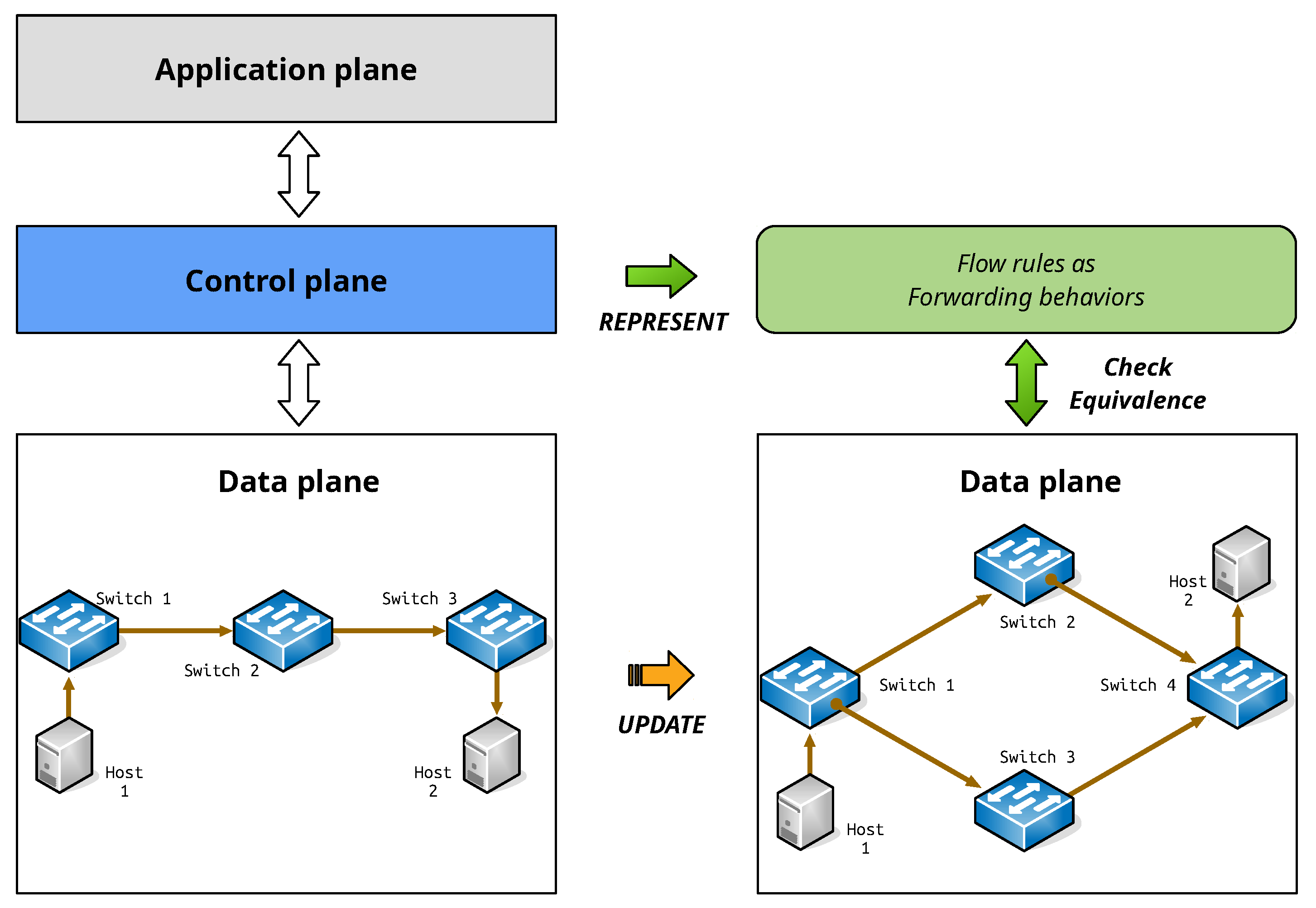
Figure 2.
An example network () with chain topology.

Figure 3.
An example network () with diamond topology.

Figure 4.
An example network () with single switch topology.

Figure 5.
An example network () with mesh topology.

Figure 6.
An example network () with data center topology.

Figure 7.
Graphical view of performance evaluation result (total processing time).


Table 1.
Performance evaluation of proposed methodology.
| No. of Ruleset | Size of Matrix () | ||||
|---|---|---|---|---|---|
| 16 | 32 | 64 | 128 | 256 | |
| Total processing time (ms) | |||||
| 10 | 29.55 | 43.80 | 103.34 | 349.38 | 1723.14 |
| 50 | 146.80 | 220.78 | 517.05 | 1755.93 | 8679.24 |
| 100 | 295.18 | 443.54 | 1039.67 | 3555.08 | 17,566.59 |
| Average processing time per matrix (ms) | |||||
| 2.95 | 4.41 | 10.35 | 35.20 | 173.85 | |
| Ratio of increase to matrix size (Compared to 16 × 16) | |||||
| 10 | ×1.00 | ×1.48 | ×3.50 | ×11.82 | ×58.31 |
| 50 | ×1.00 | ×1.50 | ×3.52 | ×11.96 | ×59.12 |
| 100 | ×1.00 | ×1.50 | ×3.52 | ×12.04 | ×59.51 |
Publisher’s Note: MDPI stays neutral with regard to jurisdictional claims in published maps and institutional affiliations. |
© 2021 by the authors. Licensee MDPI, Basel, Switzerland. This article is an open access article distributed under the terms and conditions of the Creative Commons Attribution (CC BY) license (https://creativecommons.org/licenses/by/4.0/).
Share and Cite
MDPI and ACS Style
Lee, H.; Choi, J.-Y. Static Equivalence Checking for OpenFlow Networks. Electronics 2021, 10, 2207. https://doi.org/10.3390/electronics10182207
AMA Style
Lee H, Choi J-Y. Static Equivalence Checking for OpenFlow Networks. Electronics. 2021; 10(18):2207. https://doi.org/10.3390/electronics10182207
Chicago/Turabian StyleLee, Hyuk, and Jin-Young Choi. 2021. "Static Equivalence Checking for OpenFlow Networks" Electronics 10, no. 18: 2207. https://doi.org/10.3390/electronics10182207
Note that from the first issue of 2016, this journal uses article numbers instead of page numbers. See further details here.