Article

Analysis of an Inhomogeneous Circularly Polarized Hollow Dielectric Resonator Antenna Using Perturbation Theory

1
Department of Electronics and Communication Engineering, National Institute of Technology, Delhi 110040, India
2
Department of Electronics and Communication Engineering, Maharaja Surajmal Institute of Technology, Delhi 110058, India
3
School of Computational and Integrative Sciences, Jawaharlal Nehru University, Delhi 110067, India
4
Department of Electrical & Electronics Engineering, National Institute of Technology, Delhi 110040, India
5
Department of Electronics and Communication Engineering, National Institute of Technology, Patna 800005, India
*
Author to whom correspondence should be addressed.
Electronics 2021, 10(18), 2273; https://doi.org/10.3390/electronics10182273
Submission received: 31 July 2021 / Revised: 3 September 2021 / Accepted: 10 September 2021 / Published: 16 September 2021
(This article belongs to the Special Issue Numerical Methods and Measurements in Antennas and Propagation)

Abstract

:
The perturbation approach is presented here for the first time for the analysis of an inhomogeneous circularly polarized rectangular dielectric resonator (DR) antenna (DRA). The inhomogeneous permittivity is created by perturbing a rectangle-shaped region of different material inside the rectangular dielectric resonator antenna (RDRA). The orthogonal degenerate modes with a phase difference of TE 111 x , and TE 111 y , are excited simultaneously for achieving circular polarization. A simple expression for the calculation of the resonant frequency and optimal axial ratio point for a circularly polarized (CP) inhomogeneous RDRA is presented here. Theoretical results obtained from the proposed theory are compared with theoretical, simulated, and experimental data available in the literature. The proposed analysis results show optimal axial ratio point calculations within a 1% range of the simulated and experimental data, which is better than the previous transverse transmission line reported method, having an error of approximately 4%. The advantages, accuracy, and simplicity of perturbation theory for DR are discussed in detail. The proposed theory can be easily extended for higher order modes and other shapes of material perturbation and anisotropic DRAs. The proposed technique will help in incorporation of the perturbation in the DR so that CP radiation can be obtained in an easy way.

1. Introduction

High-frequency wireless applications need an antenna which can suitably be utilized with low losses and improved performance parameters, like gain and radiation efficiency [1]. Dielectric resonator (DR) antennas (DRAs) are predominantly being investigated for fulfilling this purpose [2,3,4]. The low-loss, high-permittivity DRA gives a wider bandwidth and higher radiation efficiency compared with metallic microstrip antennas. Moreover, current research trends are moving toward the investigation of circularly polarized (CP) DRAs. The ability of CPDRAs to prevent polarization losses and antenna misalignment losses makes them overwhelmingly preferred over linearly polarized (LP) antennas [5,6]. Antennas with circularly polarized (CP) radiation patterns are preferred for establishing links between transmitting and receiver antennas of modern wireless communication systems. A number of research works showing the implementations of CPDRAs have been reported recently [7,8,9,10,11,12]. Theoretical techniques are being developed for implementing DRAs to find their different characteristics accurately [13]. The analysis of DRAs is still on the way toward the development of theoretical techniques for the prediction of their different performance parameters. The accurate resonant frequency calculation plays a vital role in the designing of application-specific antennas with optimized dimensional parameters. The numerical methods for the analysis of isolated RDRAs are noted in studies which are based on solving complex differential and integral equations. The accuracy of the perturbation approach over other reported methods [14,15,16,17] for resonant frequency calculation of an isolated RDRA [18] and an inhomogeneous stacked RDRA is reported in [19]. The perturbation approach gives a simplified equation, and the calculated frequency is within a 5% range of the measured and simulated frequencies.
Anisotropic inhomogeneous perturbed RDRAs provide enhanced gain and bandwidth over unperturbed homogeneous RDRAs. The concept of material perturbation was utilized for designing wideband enhanced gain CP RDRAs [20,21,22,23]. Analysis of DRAs with operating modes responsible for LP and CP radiations is available in the literature, based on the finite difference time domain (FDTD) method, finite element method (FEM), dielectric waveguide model (DWM), and transmission line mode. The FDTD method and FEM are performed by solving complex differential equations which require huge amounts of memory. The transverse transmission line technique [24] and mode matching technique [25] are used along with effective permittivity [26,27,28,29,30] approximation to improve their accuracy. Both of these techniques use the concept of wave number calculation in the direction of inhomogeneity.
In this paper, the perturbation approach is presented for the analysis of inhomogeneous CP RDRAs. The accurate resonant frequency of two orthogonal modes can be calculated using the perturbation approach, and the resultant frequency of two modes can be averaged for finding the optimized axial ratio point. Quasi-static approximations [31] are applied at the dielectric-dielectric discontinuity of inhomogeneous RDRAs, and finally, the change in resonant frequency is calculated in terms of the change in stored energy. The proposed approach for calculation of the resonant frequencies of orthogonal modes and the optimal axial ratio point is found to be close to the simulated, experimental, and theoretical data available in the literature. A comparison of the proposed theory with the mode matching technique and transverse transmission line technique is made. The accuracy of the validation of the theory over other reported methods is performed in terms of a very small percentage of error with respect to the simulated and experimental data.
The scope of the proposed theory is that it can be extended to other shapes of DRAs and also for higher order modes [32,33]. The material perturbation can be combined with metal wall perturbation for designing inhomogeneous anisotropic DRA material, which can be further utilized for enhanced gain and wideband CP higher order mode DRAs. It can be concluded that the perturbation approach increases antenna design flexibility by adding one more degree of freedom, and hence, it can be an important method for designing antennas with the optimized and desired radiation characteristics.
As was discussed, CPDRAs are currently being implemented due to their ability to mitigate the polarization losses that occur due to antenna misalignment and environmental effects [1]. A number of CPDRAs have recently been developed with deformed radiator shapes [8,34,35,36]. Shape deformation of the radiating element is one of the simplest methods available in the literature for obtaining the CP response [35,36]. However, prediction of the resonant frequencies of the generated orthogonal degenerate modes is still a difficult task in the case of the CPDRA. The research work noted in this paper reports a technique of prediction of the resonant frequencies of the orthogonal degenerate modes required for the CP radiation. This is the first mathematical model reported for the prediction of the resonant frequency of the CPDRA based on the perturbation. This will help with incorporation of the perturbation inside the DR so that the CP response can be obtained in the easiest way, which is the current research issue.

2. Theoretical Implementation
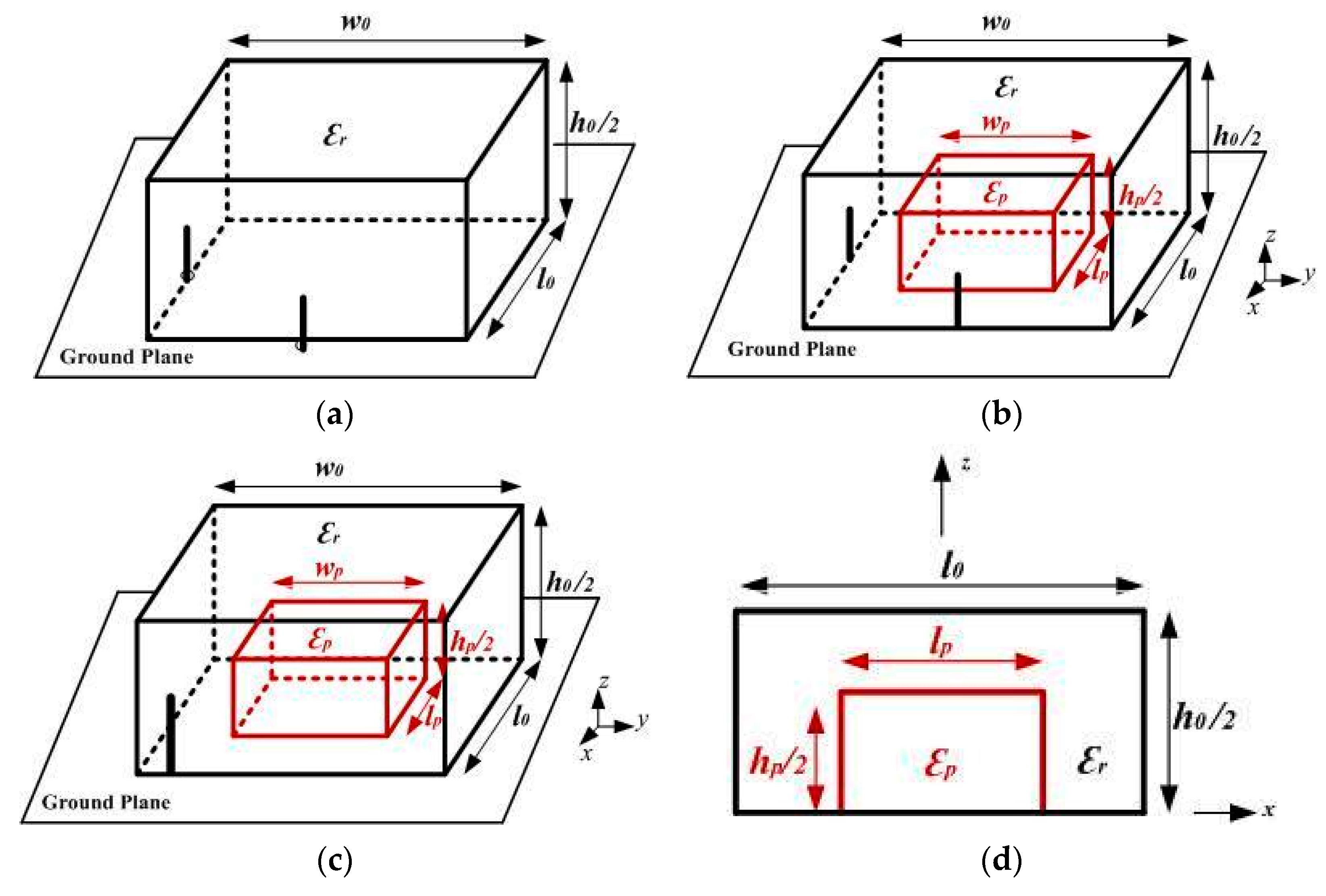
Consider that a homogeneous rectangular DRA having a permittivity ε r and dimensions l 0 × w 0 × h 0 is placed on a ground plane. A rectangular shape perturbation is created inside the original DRA, and the perturbed region has the dimensions l p × w p × h p and a permittivity ε p . The material perturbation results in an inhomogeneous RDRA. The TE 111 x and TE 111 y modes can be excited either using dual feeds at position ( l 0 / 2 ,   0 ,   0 ) and ( 0 , w 0 / 2 ,   0 ) or a single feed at position ( l 0 / 2 , w 0 / 2 ,   0 ) . Figure 1a shows the configuration of the original rectangular DRA. Figure 1b shows the configuration of an inhomogeneous RDRA. Figure 1c shows the front view of a circularly polarized inhomogeneous RDRA. Figure 1d shows the side view of a circularly polarized inhomogeneous RDRA.
For optimal excitation of the modes, probes are placed at the centers of the walls of the homogeneous RDRA, resulting in a linearly polarized field. The height of the probe can be adjusted for achieving good matching. For analysis of an inhomogeneous DRA using perturbation theory, the fields of the original DRA must be known. The field distribution depends upon the mode of excitation. The proposed perturbation approach provides a simple expression of the change in resonant frequency due to perturbation in terms of the change in the stored energy of the DRA, and the change in stored energy depends upon the perturbed region’s dimensions and the dielectric constant.
The field equations for the TE 111 x and TE 111 y modes are given in Appendix A, where A is the arbitrary constant and K x , K y , K z are the wave numbers along the x, y, and z directions, respectively. A transcendental equation is used for calculating the resonant frequency f 0 , and the wave numbers must satisfy the separation equation.
The perturbation approach for a dielectric resonator is given by Equation (1):
f p f 0 f 0 = Δ w m Δ w e w m + w e = Δ ε E P . E 0 * d τ 2 ε r E 0 2 d τ

2.1. Resonant Frequency of the T E 111 x Mode of an Inhomogeneous RDRA Using Perturbation Theory

The total stored energy for TE 111 x is found as follows:
W ex + W mx = ϵ 0 ε r A 2 l 0 w 0 h 0 16 [ k y 2 +   k z 2 ] [ 1 +   sin c ( k x l 0 ) ]
The resonant frequency of a homogeneous rectangular dielectric resonator antenna using perturbation theory [19] is given by Equation (3):
f rx = f 0 x + δ f x
δ f x = f 0 x × ( k x k 0 ) 2 1 ε r w 0 h 0 × 1 1 + sin c ( k x l 0 ) × k y 2 h 0 ( ε r 1 ) 2 k 0 2 k y 2 + k z 2 w 0 ( ε r 1 ) 2 k 0 2 k z 2 k y 2 + k z 2
When a homogeneous RDRA is excited in TE 111 x mode, having a resonant frequency f rx , it is subjected to material perturbation with permittivity ε p , and the change in the resonant frequency of TE 111 x mode can be calculated using Equation (1). The continuity of the tangential electric field components in the unperturbed and perturbed regions must be maintained (i.e., E p = E 0 ):
E p = E 0
where E 0 is the electric field of the homogeneous RDRA and E p is the electric field in the perturbed region of the inhomogeneous RDRA.
By substituting Equations (2)−(5) into Equation (1), we get Equation (6), which can be used for calculating the resonant frequency of the perturbed RDRA excited in TE 111 x mode:
f px f rx f rx = ( ε p ε r 1 ) ( k y 2 k y 2 + k z 2 ) ( w p h p ( l 0 l p ) l 0 w 0 h 0 ) ( 1 + sin c ( k x ( l 0 l p ) ) 1 + sin c ( k x l 0 ) )
f px f rx f rx = ( ε p ε r 1 ) ( h 0 2 w 0 2 + h 0 2 ) ( w p h p ( l 0 l p ) l 0 w 0 h 0 ) ( 1 + sin c ( k x ( l 0 l p ) ) 1 + sin c ( k x l 0 ) )

2.2. Resonant Frequency of the T E 111 y Mode of the Inhomogeneous RDRA Using Perturbation Theory

The above steps can be repeated for the TE 111 y mode of an RDRA.
When a homogeneous RDRA is excited in TE 111 y mode, having a resonant frequency f ry , it is subjected to material perturbation with a permittivity ε p , and the change in the resonant frequency of the TE 111 y mode can be calculated using Equation (1). Upon being solved, Equation (1) is reduced to Equation (8). The change in the resonant frequency of a perturbed RDRA excited in TE 111 y mode is given by Equation (9):
f py f ry f ry = ( ε p ε r 1 ) ( k x 2 k x 2 + k z 2 ) ( l p h p ( w 0 w p ) l 0 w 0 h 0 ) ( 1 + sin c ( k y ( w 0 w p ) ) 1 + sin c ( k y w 0 ) )
f py f ry f ry = ( ε p ε r 1 ) ( h 0 2 l 0 2 + h 0 2 ) ( l p h p ( w 0 w p ) l 0 w 0 h 0 ) ( 1 + sin c ( k y ( w 0 w p ) ) 1 + sin c ( k y w 0 ) )
Hence, the resonant frequency of the TE 111 x and TE 111 y modes of an inhomogeneous DRA can be obtained by solving Equations (7) and (9), respectively.

2.3. Resonant Frequency of a Circularly Polarized Inhomogeneous RDRA Using Perturbation Theory
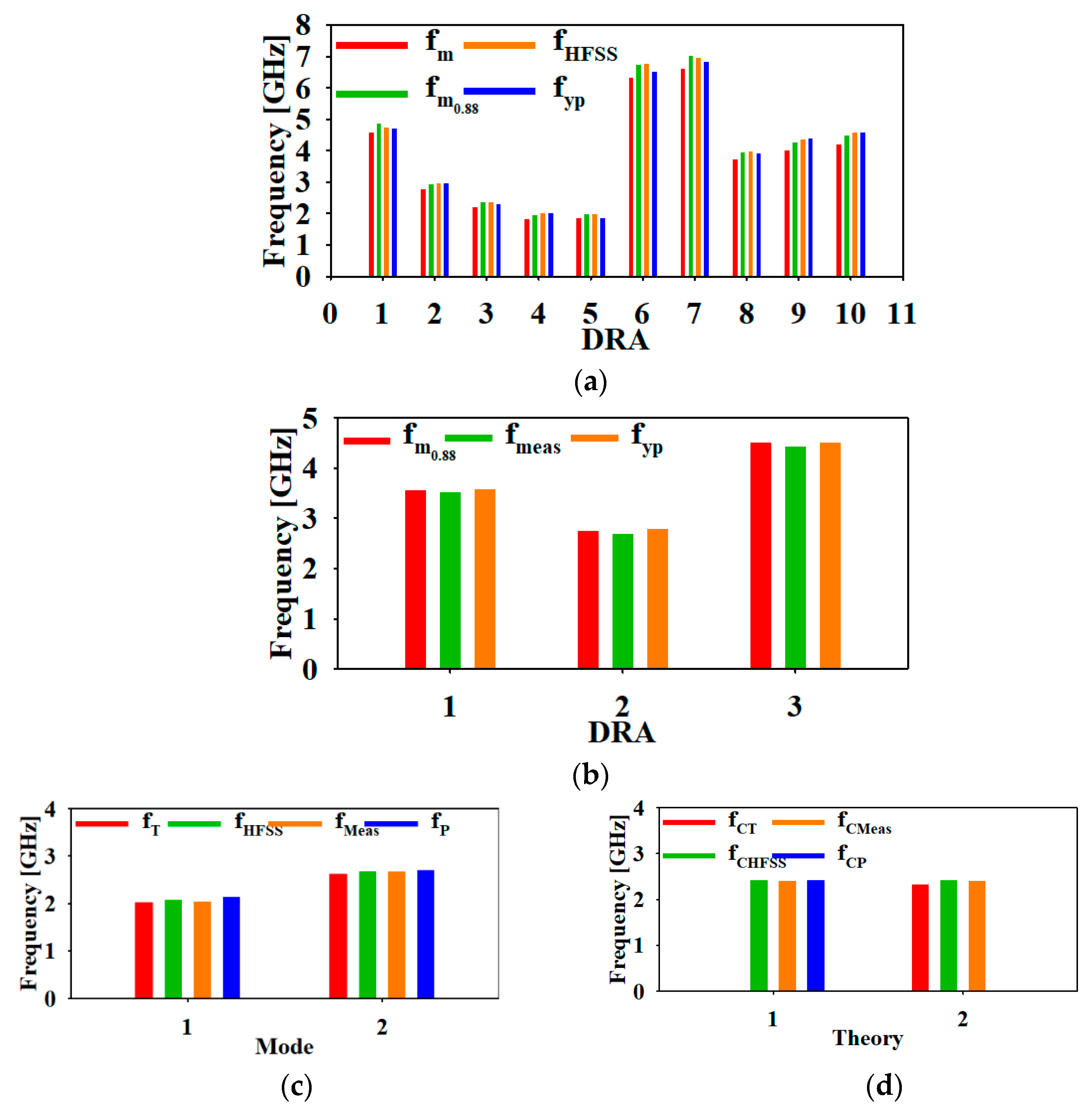
An RDRA excited in the TE 111 x and TE 111 y modes radiates like the x and y directed magnetic dipoles. The two orthogonal modes can be generated simultaneously using a single feed at position ( l 0 / 2 , w 0 / 2 ,   0 ) ) . The resultant electric field component is for the single feed at position ( l 0 / 2 , w 0 / 2 ,   0 ) .
The RDRA at (z = 0 plane) is given by following equation:
E z = A   k y cos ( k x x ) a z   ^ + A   k x cos ( k y y ) a z   ^
E z = A π w 0 cos ( k x l 0 2 ) a z   ^ + A π l 0 cos ( k y w 0 2 ) a z   ^
The two components in the resultant electric field are in the phase quadrature. The components corresponding to the TE 111 x and TE 111 y modes are A   k y cos ( k x x ) a z   ^ and Ak x cos ( k y w 0 2 ) a z   ^ , respectively.
The dimensions of the inhomogeneous RDRA ( l 0 , w 0 , h 0 , l p , w p , h p ) and the permittivity ( ε r , ε p ) must be chosen properly so that the following condition of circular polarization is satisfied:
f px Q x + f py Q y = f py f px
where f px ,   f py are the resonant frequencies corresponding to the TE 111 x and TE 111 y modes of the inhomogeneous RDRA, respectively, and Q x , Q y are the unloaded Q factors of the two modes.
The inhomogeneous RDRA will radiate like a CP RDRA at a resonant frequency f pc , which is the average of the resonant frequencies of the orthogonal modes:
f pc = f px + f py 2
For the CP RDRA, the optimal axial ratio point is approximately centered between the resonant frequencies of the orthogonal modes (i.e., the optimal AR point will be approximately at f pc ). When f py > f px , the upper resonance f py operates at a lower −3 db point, which gives a −45° phase shift relative to the f pc , and the lower resonance f px operates at an upper −3 db point, which gives a 45° phase shift relative to the f pc . The 90° phase difference is obtained between the two modes, which is required for achieving circular polarization.
The symbols used here are as follows: ε r and ε p are the dielectric constant of the original and perturbed region of the RDRA, respectively ;   f 0 x , f 0 y are the resonant frequencies of the homogeneous RDRA using the DWM method; f rx , f ry are the resonant frequency of the homogeneous RDRA using the perturbation method; f px , f py are the resonant frequencies of the inhomogeneous RDRA using the perturbation method; f pc represents the frequency corresponding to the optimal axial ratio point; f m and f m _ 0.88 are the resonant frequencies of the inhomogeneous RDRA according to the mode matching technique and effective dielectric permittivity approach, respectively; f t represents the resonant frequency of the hollow RDRA using the transverse transmission line model; and f hfss , f meas represent the simulated and measured resonant frequencies, respectively.

3. Results

The proposed perturbation theory for an inhomogeneous RDRA is compared to the theoretical results available in the literature and validated by comparing the proposed theoretical results with the simulated and measured results available in the literature.
The perturbation theory is verified for the single-mode TE 111 y of the inhomogeneous RDRA [25]. Analysis of the horizontally inhomogeneous RDRA using the mode matching technique is presented in [25], and this is the special case of the proposed theory where l p = l 0   & h p = h 0 . The TE 111 y mode is excited in the RDRA ( l 0 × w 0 × h 0 ,   ε r ) and subjected to material perturbation ( l 0 × w p × h 0 ,   ε p ) along the y-axis. The expression of the resonant frequency can be obtained by solving Equation (1) for the TE 111 y mode. The resonant frequencies calculated were compared to the theoretical, simulated, and measured resonant frequencies (Tables 1 and 2 of [25]) of the inhomogeneous RDRA. Table 1 shows the comparison of the proposed perturbation theory for inhomogeneous RDRAs to the mode matching technique [25] for inhomogeneous RDRAs. The error between the theoretical frequencies calculated from the proposed method and simulated frequencies was found to be within an acceptable range (Table 1). A comparison between the mode matching technique and the proposed theory is shown graphically in Figure 2a,b.
Theoretical and experimental validation of the resonant frequency with Table 2 of [25] for horizontally inhomogeneous rectangular DRAs is shown in Table 2. The small percentage of error between the calculated resonant frequency and the measured resonant frequency is an indicator of the accuracy of the proposed perturbation method.
The theory is further validated for circular polarization and compared to the theoretical, simulated, and experimental results as shown in [24]. A circularly polarized hollow rectangular DRA is analyzed in [24]. An equivalent circuit model is used for calculating the wave number and DWM method for resonant frequency calculation. The transverse transmission line technique was used along with the effective dielectric constant method to obtain the characteristic equation of a hollow rectangular RDRA.
A hollow RDRA is an inhomogeneous RDRA where ε p = ε 0 . In [24], the CP hollow DRA is designed for 2.4 GHz. This is the case for an RDRA (21.7 × 57.5 × 46 mm 3 ,   ε r = 9.4 ) subjected to material perturbation (11.8 × 48.2 × 31.8 mm 3 ,   ε p = ε 0 ) for making a hollow DRA. Equations (7) and (9) can be used for calculating the resonant frequency of the TE 111 x and TE 111 y modes, respectively. The calculated percentage error between the resonant frequencies calculated from the transverse transmission line technique [24] and perturbation theory is shown in the table in [3]. A comparison of the transverse transmission line technique and the proposed theory is shown graphically in Figure 2c,d. Mode 1 in Figure 2c corresponds to the TE 111 x mode, and Mode 2 corresponds to the TE 111 y mode. Theory 1 in Figure 2d corresponds to the proposed method, and Theory 2 corresponds to the transverse transmission line technique.
The center frequency corresponding to the optimal axial ratio point can be calculated using Equation (13). Table 4 shows experimental validation of the proposed theory for the calculation of the optimal axial ratio point of a circularly polarized hollow RDRA. The proposed perturbation approach yielded a very accurate estimation of the optimal AR point for designing a CP inhomogeneous RDRA. Table 4 shows the accuracy of the given theory over the previously reported theory. The suggested theory gave an error rate of around 0.2% from the simulated results and within 1% with the measured results, which was better than earlier reported transverse transmission line method, having an error of 3.9% from the simulated results and 3% with the measured results.
Hence, the perturbation theory for circular polarized inhomogeneous RDRAs gives simpler equations for accurate calculation of the resonant frequency and the optimal axil ratio point. The simplicity and accuracy of the proposed theory over other reported methods is justified. The method can be applied for designing any arbitrary circularly polarized inhomogeneous RDRA with an enhanced degree of freedom in terms of the perturbed region dimensions and permittivity. Anisotropic structures obtained by material perturbation can be utilized for designing DRAs with enhanced gain and bandwidth. The theory can be easily extended for other shapes of DRAs and other shapes of perturbation.

4. Conclusions

The concept of material perturbation is applied here for calculating the optimal axial ratio point of a circularly polarized perturbation inhomogeneous rectangular RDRA by making use of the change in resonant frequency of simultaneously excited orthogonal modes TE 111 x and TE 111 y . The theoretical results obtained from a simple equation are compared with the previously reported theories (mode matching technique and transverse transmission line technique). The results are also compared to simulated and experimental results, and the accuracy of the perturbation theory over the reported methods is validated. The proposed method of calculation of the resonant frequency corresponding to the optimal axial ratio provided an error of around 0.2% from the simulated results and within 1% of the measured results, which is better than the earlier reported method, having an error of approximately 4%. The theory can be extended for studying the effect of perturbation on the Q factor of the orthogonal modes, higher order modes, and different shapes of perturbation of DRAs.

Author Contributions

N.S. formulated the problem, defined the solution, and obtained the results. B.K.K. and A.A. supervised the whole research work. G.V. helped in defining the problem-specific research gap. All authors have read and agreed to the published version of the manuscript.

Funding

This research received no external funding.

Conflicts of Interest

The authors declare no conflict of interest.

Appendix A

Field Equations for TE 111 x and TE 111 y Mode of Homogeneous Rectangular DRA
TE 111 x Mode TE 111 y Mode
E x = 0 E y = 0
E y = A k z cos ( k x x ) cos ( k y y ) sin ( k z z ) E x = A k z cos ( k x x ) cos ( k y y ) sin ( k z z )
E z = A k y cos ( k x x ) sin ( k y y ) cos ( k z z ) E z = A k x sin ( k x x ) cos ( k y y ) cos ( k z z )
H x = A k y 2 + k z 2 j ω μ 0 cos ( k x x ) cos ( k y y ) cos ( k z z ) H x = A k x k z j ω μ 0 sin ( k x x ) sin ( k y y ) cos ( k z z )
H y = A k x k y j ω μ 0 sin ( k x x ) sin ( k y y ) cos ( k z z ) H y = A k x 2 + k z 2 j ω μ 0 cos ( k x x ) cos ( k y y ) cos ( k z z )
H z = A k x k z j ω μ 0 sin ( k x x ) cos ( k y y ) sin ( k z z ) H z = A k y k z j ω μ 0 cos ( k x x ) sin ( k y y ) sin ( k z z )
k x tan ( k x l 0 2 ) = ( ε r 1 ) k 0 2 k x 2 k y tan ( k y w 0 2 ) = ( ε r 1 ) k 0 2 k y 2
k x 2 + k y 2 + k z 2 = ε r k 0 2 k x 2 + k y 2 + k z 2 = ε r k 0 2
k y = π w 0 , k z = π h 0 k x = π l 0 , k z = π h 0
A is the arbitrary constant and K x , K y , K z are the wave numbers along the x, y, and z directions, respectively.

References

  1. Varshney, G. Gain and Bandwidth Enhancement of a Singly Fed Circularly Polarized Dielectric Resonator Antenna. IET Microw. Antennas Propag. 2020, 14, 1323–1330. [Google Scholar] [CrossRef]
  2. Ali, I.; Jamaluddin, M.H.; Gaya, A.; Rahim, H.A. A Dielectric Resonator Antenna with Enhanced Gain and Bandwidth for 5G Applications. Sensors 2020, 20, 675. [Google Scholar] [CrossRef] [PubMed] [Green Version]
  3. Yang, M.D.; Pan, Y.M.; Sun, Y.X.; Leung, K.W. Wideband Circularly Polarized Substrate-Integrated Embedded Dielectric Resonator Antenna for Millimeter-Wave Applications. IEEE Trans. Antennas Propag. 2020, 68, 1145–1150. [Google Scholar] [CrossRef]
  4. Pan, Y.M.; Leung, K.W.; Luk, K.M. Design of the millimeter-wave rectangular dielectric resonator antenna using a higher-order mode. IEEE Trans. Antennas Propag. 2011, 59, 2780–2788. [Google Scholar] [CrossRef]
  5. Varshney, G.; Singh, R.; Pandey, V.S.; Yaduvanshi, R.S. Circularly Polarized Two-Port MIMO Dielectric Resonator Antenna. Prog. Electromagn. Res. M 2020, 91, 19–28. [Google Scholar] [CrossRef]
  6. Gotra, S.; Varshney, G.; Yaduvanshi, R.S.; Pandey, V.S. Dual-band circular polarisation generation technique with the miniaturisation of a rectangular dielectric resonator antenna. IET Microw. Antennas Propag. 2019, 13, 1742–1748. [Google Scholar] [CrossRef]
  7. Majeed, A.H.; Abdullah, A.S.; Elmegri, F.; Sayidmarie, K.H.; Abd-Alhameed, R.A.; Noras, J.M. Dual-segment S-shaped aperture-coupled cylindrical dielectric resonator antenna for X-band applications. IET Microw. Antennas Propag. 2015, 9, 1673–1682. [Google Scholar] [CrossRef] [Green Version]
  8. Varshney, G.; Gotra, S.; Pandey, V.S.; Yaduvanshi, R.S. Inverted-Sigmoid Shaped Multi-Band Dielectric Resonator Antenna with Dual Band Circular Polarization. IEEE Trans. Antennas Propag. 2018. [Google Scholar] [CrossRef]
  9. Kishk, A.A. An elliptic dielectric resonator antenna designed for circular polarization with single feed. Microw. Opt. Technol. Lett. 2003, 37, 454–456. [Google Scholar] [CrossRef]
  10. Turitsyna, E.G.; Webb, S. Simple design of FBG-based VSB filters for ultra-dense WDM transmission ELECTRONICS LETTERS 20th January 2005. Electron. Lett. 2005, 41, 40–41. [Google Scholar] [CrossRef]
  11. Shaik, L.A.; Saha, C.; Arora, S.; Das, S.; Siddiqui, J.Y.; Iyer, A.K. Bandwidth control of cylindrical ring dielectric resonator antennas using metallic cap and sleeve loading. IET Microw. Antennas Propag. 2017, 11, 1742–1747. [Google Scholar] [CrossRef]
  12. Ghosh, B.; Bhattacharya, D.; Sinha, P.D.; Werner, D.H. Design of Circular Waveguide Annular Slot-Coupled Two-Layer DRA for Linear and Circular Polarizations. IEEE Antennas Wirel. Propag. Lett. 2020, 19, 1012–1016. [Google Scholar] [CrossRef]
  13. Petosa, A.; Ittipiboon, A. Dielectric Resonator Antennas: A Historical Review and the Current State of the Art. IEEE Antennas Propag. Mag. 2010, 52, 91–116. [Google Scholar] [CrossRef]
  14. Gürel, Ç.S.; Co, H.; Akal, Ö. Accurate Resonant Frequency Computation of Multisegment Rectangular Dielectric Resonator Antennas. J. Electromagn. Waves 2010, 37–41. [Google Scholar] [CrossRef] [Green Version]
  15. Rashidian, A.; Forooraghi, K.; Tayefeh, M.R. Design algorithm of multisegment dielectric resonator antennas (MSDRAs). In Proceedings of the Asia-Pacific Radio Science Conference, Qingdao, China, 24–27 August 2004; pp. 134–137. [Google Scholar]
  16. Petosa, A.; Simons, N.; Siushansian, R.; Ittipiboon, A.; Cuhaci, M. Design and Analysis of Multisegment Dielectric Resonator Antennas. IEEE Trans. Antennas Propag. 2000, 48, 738–742. [Google Scholar] [CrossRef]
  17. Rashidian, A.; Forooraghi, K.; Allgodarz, M.T. Investigations on two-segment dielectric resonator antennas. Microw. Opt. Technol. Lett. 2005, 45, 533–537. [Google Scholar] [CrossRef]
  18. Fakhte, S.; Oraizi, H. Derivation of the resonant frequency of rectangular dielectric resonator antenna by the perturbation theory. Appl. Comput. Electromagn. Soc. J. 2016, 31, 894–900. [Google Scholar]
  19. Sehrawat, N.; Kanaujia, B.K.; Agarwal, A. Calculation of the resonant frequency of a rectangular dielectric resonator antenna using perturbation theory. J. Comput. Electron. 2019, 18, 211–221. [Google Scholar] [CrossRef]
  20. Darimireddy, N.K.; Reddy, R.R.; Prasad, A.M. Wideband Circularly Polarized Cylindrical Dielectric Resonator Antennas with Rectangular Curved Slots [Antenna Applications Corner]. IEEE Antennas Propag. Mag. 2020, 62, 65–73. [Google Scholar] [CrossRef]
  21. Trinh-Van, S.; Yang, Y.; Lee, K.Y.; Hwang, K.C. A wideband circularly polarized pixelated dielectric resonator antenna. Sensors 2016, 16, 1349. [Google Scholar] [CrossRef] [PubMed] [Green Version]
  22. Reddy, R.V.; Ameen, M.; Chaudhary, R.K.; Kumar Gangwar, R. Compact wideband circularly polarized rectangular DRA with right angled conformal strip feed. In Proceedings of the 2019 IEEE Indian Conference on Antennas and Propogation (InCAP), Ahmedabad, India, 19–22 December 2019; pp. 4–7. [Google Scholar] [CrossRef]
  23. Trinh-Van, S.; Yang, Y.; Lee, K.Y.; Hwang, K.C. Single-Fed Circularly Polarized Dielectric Resonator Antenna with an Enhanced Axial Ratio Bandwidth and Enhanced Gain. IEEE Access 2020, 8, 41045–41052. [Google Scholar] [CrossRef]
  24. Lu, K.; Leung, K.W.; Pan, Y.M. Theory and experiment of the hollow rectangular dielectric resonator antenna. IEEE Antennas Wirel. Propag. Lett. 2011, 10, 631–634. [Google Scholar] [CrossRef]
  25. Maity, S.; Gupta, B. Theory and experiments on horizontally inhomogeneous Rectangular Dielectric Resonator Antenna. AEU-Int. J. Electron. Commun. 2017, 76, 158–165. [Google Scholar] [CrossRef]
  26. Schaap, M.G.; Robinson, D.A.; Friedman, S.P.; Lazar, A. Measurement and Modeling of the TDR Signal Propagation through Layered Dielectric Media. Soil Sci. Soc. Am. J. 2003, 67, 1113–1121. [Google Scholar] [CrossRef]
  27. Chan, Y.; Knight, J. Determining water content and saturation from dielectric measurements in layered materials commonly made to determine water and in turn to determine accuracy with which water content or saturation information can be obtained from dielectric homogeneous mi. Water Resour. 1999, 35, 85–93. [Google Scholar] [CrossRef]
  28. Chan, C.Y.; Knight, R.J. Laboratory measurements of electromagnetic wave velocity in layered sands. Water Resour. Res. 2001, 37, 1099–1105. [Google Scholar] [CrossRef]
  29. Robinson, D.A.; Jones, S.B.; Wraith, J.M.; Or, D.; Friedman, S.P. A Review of Advances in Dielectric and Electrical Conductivity Measurement in Soils Using Time Domain Reflectometry. Vadose Zo. J. 2003, 2, 444. [Google Scholar] [CrossRef]
  30. Park, C.H.; Behrendt, A.; LeDrew, E.; Wulfmeyer, V. New approach for calculating the effective dielectric constant of the moist soil for microwaves. Remote Sens. 2017, 9, 732. [Google Scholar] [CrossRef] [Green Version]
  31. Harrington, R.F. Times Harmonic Electromagnetic Fields; McGraw-Hill: New York, NY, USA, 1961. [Google Scholar]
  32. Petosa, A.; Thirakoune, S. Rectangular dielectric resonator antennas with enhanced gain. IEEE Trans. Antennas Propag. 2011, 59, 1385–1389. [Google Scholar] [CrossRef]
  33. Abdulmajid, A.A.; Khalil, Y.; Khamas, S. Higher Order Mode Circularly Polarized Two-Layer Rectangular Dielectric Resonator Antenna. Antennas Wirel. Propag. Lett. 2018, 1225, 1–4. [Google Scholar] [CrossRef]
  34. Varshney, G. Wideband THz absorber: By merging the resonance of dielectric cavity and graphite disk resonator. IEEE Sens. J. 2020, 21, 1635–1643. [Google Scholar] [CrossRef]
  35. Kumar, R.; Varshney, G.; Yaduvanshi, R.S.; Kumar, D.; Pandey, V.S. Dual-Band Dielectric Resonator Antenna with Multi- Frequency Circular Polarization. IET Microw. Antennas Propag. 2020, 14, 435–439. [Google Scholar] [CrossRef]
  36. Patel, P.; Mukherjee, B.; Mukherjee, J. Wideband Circularly Polarized Rectangular Dielectric Resonator Antennas using Square Shaped Slots. IEEE Antennas Wirel. Propag. Lett. 2015, 15, 1309–1312. [Google Scholar] [CrossRef]
Figure 1. (a) Configuration of the original RDRA. (b) Configuration of the inhomogeneous RDRA. (c) Front view of the circularly polarized inhomogeneous RDRA. (d) Side view of the circularly polarized inhomogeneous RDRA.
Electronics 10 02273 g001
Figure 2. (a,b) Comparison of the mode matching technique with the proposed theory (refer to Table 1 and Table 2). (c,d) Comparison of the transverse transmission technique with the proposed theory (refer to Table 3 and Table 4).
Electronics 10 02273 g002
Table 1. Comparison of resonant frequencies with the mode matching theory and the simulated resonant frequencies of a horizontally inhomogeneous rectangular dielectric resonator antenna (HIRDRA) (Table 1 [25]).
DRA ε r ε p Dimensions (mm) f m [25] f m _ 0.88 [25] f hfss [25] f y p % Error
Δ f m = f m f y p f y p
% Error
Δ f m _ 0.88 = f m _ 0.88 f y p f y p
% Error
Δ f h f s s = f h f s s f y p f y p
l 0 × w p × h 0 w p
1251010 × 10 × 1654.5654.8654.7374.6992−2.93.50.8
2802510 × 9 × 2462.7612.9422.9542.9632−6.8−0.7−0.3
3804015 × 4 × 3012.2152.3592.3652.2818−2.93.43.6
41005010 × 20 × 20101.8361.9572.0112.0228−9.23.3−0.6
51001015 × 8 × 2031.8501.9721.9821.84560.26.87.4
640106 × 5 × 826.3246.7426.7546.4953−2.63.84.0
740106 × 4 × 1226.5927.0236.9666.8365−3.62.71.9
8100306 × 6 × 1233.7073.9523.9773.9166−5.40.91.5
980405 × 9 × 1244.0004.2644.3534.3974−9.0−3.0−1.0
1080405 × 5 × 1214.1934.4694.5904.5719−8.3−2.30.4
According to [25], the frequency f m [25] is the resonant frequency of the HIRDRA calculated using the mode matching technique. Frequency f m _ 0.88 [25] of the HIRDRA is calculated by considering the effective permittivity approximation ( ε r   eff = * ε r & ε p   eff = * ε p ).
Table 2. Theoretical and experimental validation of the resonant frequency with Table 2 of [25] of a horizontally inhomogeneous rectangular DRA.
DRA ε r ε p Dimensions (mm) f m _ 0.88 [25] f meas [25] f y p % Error
Δ f m _ 0.88 = f m _ 0.88 f y p f y p
% Error
Δ f m e a s = f m e a s f y p f y p
l 0 × w 0 × h 0 w p
1251025 × 42 × 10253.5693.523.5845−0.4−1.8
2251025 × 8 × 5052.7572.682.794−1.3−4.1
3102525 × 30 × 1054.5114.434.50440.1−1.7
Table 3. Comparison of the resonant frequencies of the CP hollow inhomogeneous RDRA [24] and hollow RDRA having dimensions l 0 = 21.7, w 0 = 57.5, h 0 = 46, l p = 11.8, w p = 48.2, and h p = 31.8, with a dielectric constant ε r = 9.4 , ε p = ε 0 .
Mode f T [24] f h f s s   [24] f m e a s [24] f P % Error
Δ f T = f T f P f P
% Error
Δ f h f s s = f h f s s f P f P
% Error
Δ f m e a s = f m e a s f P f P
TE 111 x 2.032.082.042.14−5.6−5.1−3.3
TE 111 y 2.632.672.2.672.71−3.2−3.5−1.7
Table 4. Experimental validation of the proposed theory for calculation of the optimal axial ratio point of a circularly polarized hollow RDRA having dimensions l 0 = 21.7, w 0 = 57.5, h 0 = 46, l p = 11.8, w p = 48.2, and h p = 31.8, with a dielectric constant ε r = 9.4 , ε p = ε 0 .
TheoryOptimal Axial Ratio Point% Error
Δ f h f s s = f h f s s f C P f C P
% Error
Δ f m e a s = f m e a s f C P f C P
f C T [24] f c h f s s [24] f c m e a s [24] f C P
Proposed-2.242.42.4250.21
Proposed [24]2.33 *2.242.4-3.93
* The average of 2.03 and 2.63 is 2.33. According to Figure 7 of [24], the simulated optimal axial ration point ( f chfss ) is at 2.42 GHz, and the measured optimal axial ration point ( f cmeas ) is 2.4 GHz. The optimal axial ratio point for the proposed theory is calculated using Equation (13).
Publisher’s Note: MDPI stays neutral with regard to jurisdictional claims in published maps and institutional affiliations.

