Article

Memristors as Candidates for Replacing Digital Potentiometers in Electric Circuits

School of Electrical Engineering, University of Belgrade, Bulevar Kralja Aleksandra 73, P.O. Box 35-54, 11120 Belgrade, Serbia
*
Author to whom correspondence should be addressed.
Electronics 2021, 10(2), 181; https://doi.org/10.3390/electronics10020181
Submission received: 13 December 2020 / Revised: 7 January 2021 / Accepted: 12 January 2021 / Published: 15 January 2021
(This article belongs to the Section Circuit and Signal Processing)

Abstract

:
Digital potentiometers are substantial components for the design of many mixed-signal electronic circuits and systems. Their capability to program resistance value almost instantly provides hardware designers an additional level of freedom. Unfortunately, this feature is limited to DC and lower frequencies, due to parasitic effects. Nowadays, memristors as continuously tunable resistors are becoming candidates for potentiometer successors. Memristors are two-terminal non-volatile devices which have less significant parasitic effects and a wide resistance range. The memristance value can be changed on the fly. Using nanotechnology, memristor implementation has a nanoscale footprint with nanosecond transition between resistive states. In this paper, we present a comparison between the frequency characteristics of digital potentiometers and the only commercially available memristors. Memristor parasitic effects dominate at higher frequencies which extends the bandwidth. In order to present the advantages of memristive circuits, we have analyzed and implemented tunable circuits such as a voltage divider, an inverting amplifier, a high-pass filter, and a phase shifter. A commercially available memristor by KnowM Inc. is used for this purpose. Experimental results obtained by the measurements verify that a memristor has equal or better characteristics than a digital potentiometer. Memristive realizations of voltage dividers and inverting amplifiers have a wider bandwidth, while filters and phase shifters with a memristor have almost identical frequency characteristics as the corresponding realizations with a digital potentiometer.

1. Introduction

The memristor is the fourth fundamental circuit element. It was envisioned and postulated by Chua [1]. The four fundamental two-terminal (one-port) elements of electric circuits can be axiomatically defined via a constitutive relation between a pair of circuit variables [2]. The four basic circuit variables are current i ( t ) , voltage v ( t ) , flux φ ( t ) , and charge q ( t ) . By definition,
i ( t ) = d q ( t ) d t
q ( t ) = t i ( τ ) d τ = q 0 + t 0 t i ( τ ) d τ
q 0 = t 0 i ( τ ) d τ
q 0 is the initial state of q ( t ) at the initial time t = t 0 ,
v ( t ) = d φ ( t ) d t
φ ( t ) = t v ( τ ) d τ = φ 0 + t 0 t v ( τ ) d τ
φ 0 = t 0 v ( τ ) d τ
φ 0 is the initial state of φ ( t ) at the initial time t = t 0 .
The variables q ( t ) and φ ( t ) are time integrals of the variables i ( t ) and v ( t ) , respectively; they need not be associated with a real physical charge or a real physical flux.
The axiomatic definition of the fundamental electric circuit elements is shown in Figure 1.
The ideal charge-controlled memristor is defined by the constitutive relation
φ = Φ ( q )
via the q -dependent Ohm’s law
v = M ( q ) i ,   M ( q ) = d Φ ( q ) d q ,
where M ( q ) is called the memristance at q . Φ ( q ) is a continuous and piecewise-differentiable function with bounded slopes. The memristance at any time depends on the entire past history of the element’s current.
Probably, the key feature of the memristor is that it exhibits analog non-volatile memory: when a memristor is opened/short-circuited, or when the excitation/power is switched off, the memristor holds its memristance/state.
Practically, the memristor can be identified by its distinctive “fingerprint”:
(1)
Assume arbitrary initial conditions.
(2)
Excite the device by a periodic bipolar voltage or current with both positive and negative values (the mean value should be zero, no DC component).
(3)
Observe a pinched hysteresis loop, a double-valued Lissajous figure passing through the origin, confined to the first and the third quadrants of the i - v plane.
(4)
Increase the excitation frequency (theoretically to infinity) and observe that the loop shrinks continuously to a straight line whose slope depends on the excitation waveform.
According to KnowM Inc. (Santa Fe, NM, USA), each memristor should be formed (conditioned) prior to further utilization. The forming is performed by exciting a discrete memristor with a sinusoidal waveform for several seconds (for at least 20 cycles): at a frequency of 100 Hz, with an amplitude gradually increasing from 0.1 V to 2.5 V, until the expected pinched hysteresis loop (Lissajous figure) appears.
The memristor forming circuit is shown in Figure 2. The current-limiting resistor is 47 kΩ. After forming the device, the current-limiting resistor was changed to 10 kΩ and the generator frequency was varied, from 1 Hz to 100 Hz, in order to produce a group of Lissajous figures. The “memristor fingerprint test” explained above is illustrated by the measurements of a KnowM memristor, and the corresponding hysteresis loops, Figure 3.
The firstly produced HP memristor [4] consists of a two-layer thin film (TiO2), sandwiched between two platinum electrodes. The first layer is doped with oxygen vacancies, so it behaves as a semiconductor. The other region is undoped and has an insulating property. Memristance value is changed by changing the width of the two regions: as the doped region expands in the undoped region, the total resistance is being reduced, and vice versa. The HP memristor is characterized with resistance values in ON (around 1 kΩ) and OFF (around 100 kΩ) states. HP is profiling memristors for AI and computing.
The only commercially available memristors by KnowM Inc. [5] are based on work of Prof. Campbell [6]. The KnowM memristors are metal ion-conducting devices. They rely on the movement of silver ions (Ag+) into channels within the active layer to change the device resistance. Permanent conductive channels that contain silver (Ag) agglomeration sites are generated by metalcatalyzed reactions within the device’s active layer. The memristor resistance is determined by the amount of silver (Ag) within the channel. The reported dimensions of a single memristor cell are around 1 µm. The memristance in the OFF state is at least 1 MΩ (if it was not irreversibly reduced to around 100 kΩ by the application of a current greater than 1 mA) and in the ON state it is around 400 Ω. Power handling is around 3 mW (5 dBm). KnowM is profiling their memristors for AI usage, but they seem to be suitable for electronic circuits as well.
The first RF memristor [7] was fabricated on an intrinsic silicon wafer with a 380 nm thick thermally grown silicon dioxide layer. A silver (Ag) layer was used as a terminal for one side, and a gold (Au) with a thin titanium (Ti) adhesion layer as a terminal for the other side. The terminals are separated by a 35 nm wide air gap. The formation/rupture of multiple conductive filaments between two electrodes is dictating memristor states. In the ON state, there is always at least one conductive filament, which leads to the low resisting state. In the OFF state, ruptures are dominant, so this state is dominantly defined by the capacitances of the gaps between the filaments. The Pi’s memristor is accurately modelled with a small resistance value (around 3.6 Ω) in the ON state, and a capacitor in the OFF state (around 1.4 fF). The memristor is operational at frequencies from 10 MHz to 110 GHz, with insertion loss of around 0.3 dB in the ON state, and isolation of around 30 dB in the OFF state. Power handling is around 20 dBm.
More recent RF memristors (switches) are being developed by a group from the University of Austin. They reported [8] the observation of stable non-volatile resistance switching in single-layer atomic sheets sandwiched between metal electrodes. The switching mechanism is attributed to ionic diffusion, filament, and interfacial redox in bulk oxides and electrolytes. The improved solution, based on monolayer hBN, was published in 2019 [9]. The structure is rated to ~0.33 nm length, has an insertion loss of no more than 0.2 dB and isolation of no less than 15 dB for frequencies up to 110 GHz. Power handling is around 20 dBm. Switching time is less than 15 ns with applied voltage of around 1 V.
A memristor is a two-terminal element that is able to change its state “on the fly”. A memristor’s resistance, known as memristance, is determined by the history of applied voltage and/or current. The key features of a memristor are that it is a non-volatile and nanoscale element with tunable memristance in a wide resistance range. These features encouraged scientists and engineers to propose a lot of potential applications of memristors. Some of the fabricated memristors have the capability to switch between low and high memristances (ON and OFF states), thus acting as electronic switches. In other cases, the memristance value can be tuned continuously between ON and OFF states [10].
Memristors with binary states are widely used in artificial intelligence. A Chinese group reported a fully hardware-implemented memristor convolutional neural network [11]. Memristors are components compatible with CMOS technology [12] which can be used to enhance processor performance and realize applications based on artificial intelligence. The fact that memristors are one-port devices enables them to be used as memory and processing components at the same time.
Memristive RF switches [7,9] enable reconfigurability of microwave devices. There are a lot of applications where memristors are used in RF/microwave circuitries [13,14] such as filters [15,16] and tunable inductors [17,18]. In [19], authors proposed a reconfigurable phase shifter based on a memristor instead of a traditional switch as a PIN diode. This memristive realization reduces the power consumption while preserving the functionality. Unfortunately, RF memristors are not commercially available.
Digital potentiometers (called just potentiometers in the rest of the paper) have a wide application in mixed-signal electronic circuits and systems such as tunable amplifiers [20,21] and sensors [22,23]. In the last decade, memristive applications were being proposed for the realization of tunable amplifiers [24] and programmable filters [24,25]. Circuit dynamics with memristors was analyzed and a memristor based oscillator was proposed in [26]. Memristance programming is one of the major difficulties in analog memristor operation. It is not easy to obtain the target resistance value quickly and accurately at the same time. Memristance setup is analyzed in some recent researches [27,28,29,30].
In this paper, we outline the advantages of memristors compared to potentiometers. We use self-directed-channel memristors with tungsten (W) dopant [6], packaged in an encapsulated edge board. The encapsulated edge board is placed in a PCI-E 36 breakout board [31]. The KnowM memristor is compared to the best in class potentiometer from Analog Devices [32]. Limitations of potentiometers are taken as a starting point. Potentiometers have shunt parasitic capacitances that reduce its operating frequency range. Memristors are smaller in size and do not need a constant power supply. Potentiometers have a more restricted range of resistance values compared to memristors.
The memristor impedance was measured and compared to that of a potentiometer. The results were discussed along with important differences between the inherent properties of the two devices. Moreover, to further the comparative analysis, several memristor based implementations are provided: a voltage divider, an inverting amplifier, a high pass filter, and a phase shifter.

2. Comparison between Frequency Characteristics of the Potentiometer and Memristor

Several companies develop potentiometers. Apparently, only Analog Devices [33] is capable of providing devices with a nominal resistor tolerance error lower than 20%. Analog Devices claims that the maximal tolerance for some of their potentiometers is 1%. This fact qualifies them as the best in class, so their model of potentiometer was used in this research.
The AC model of the potentiometer is presented in Figure 4 [34], whereas its 3 dB bandwidth (BW) can be determined using an extended schema, represented with dotted lines. The bandwidth of the potentiometer is dependent on configuration. For the experimental test circuit in Figure 4, capacitor CA can be neglected because it is in parallel with an ideal voltage generator. The effect of capacitor CB can be neglected when terminal B is grounded. For the circuit presented in Figure 4, if the A terminal is the input with the grounded B terminal, then the W terminal is the output, and the bandwidth is equal to
BW P = 1 2 π ( R WA | | R WB ) C W .
Most potentiometers with a 1% precision, such as AD5270, have the following shunt parasitic capacitances CA = CB = 90 pF, CW = 40 pF. Those are also the lowest parasitic capacitances that Analog Devices reports for 1% precision potentiometers.
In order to analyze parasitic effects of the potentiometer, we connect the potentiometer into a voltage divider. We analyzed two test circuits (configurations) as shown in Figure 5. For the first configuration in Figure 5a, we find that the potentiometer impedance is equal to
Z P a ( j ω ) = R WA 1 j ω C A ,
where f represents the operating frequency, and ω = 2πf. Parameter RWA presents the resistance between terminals W and A. For the second configuration in Figure 5b, the potentiometer impedance is equal to
Z P b ( j ω ) = ( R WA R WB ) 1 j ω C W ,
where RWB presents the resistance between terminals W and B.
For the two analyzed circuit configurations, the second one (Figure 5b) has the wider bandwidth because capacitance CW is less than half of capacitance CA. For the circuit in Figure 5b, resistors RWA and RWB are connected in parallel, which implies a twice lower resistance. In the rest of the paper, the potentiometer is modeled with a variable resistor (RP = RWA||RWB) and a parasitic capacitor (CP = CW = 40 pF), i.e., Z P = Z P b .
In the open literature, we have not found adequate simulation models of KnowM’s memristors that would fit our experimental setup. Memristor models that realize transitions between states are presented in [35,36] for frequencies up to 100 Hz, whereas a binary memristor is modeled in [37]. Accordingly, an experimental approach is undertaken to find the impedance characteristics of the memristor. Memristance programming is realized using Digilent Analog Discovery 2 (AD2) instrumentation tool [38] together with KnowM’s software package for memristor analysis [39]. However, the memristor setup circuitry is not in the focus of this research.
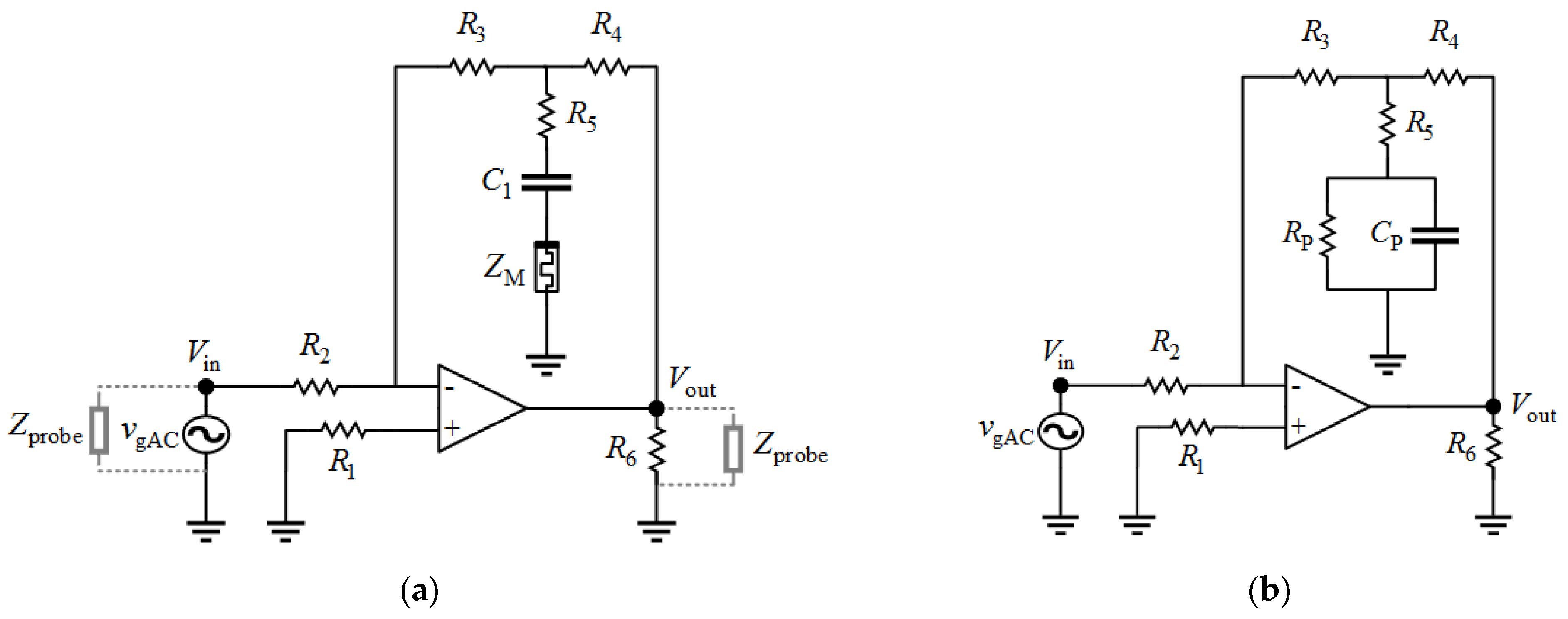
We used a voltage divider to determine the memristor impedance (Figure 6a). Measurements using an oscilloscope introduce additional unknowns—probes’ impedances. The probe’s impedance can be neglected at the circuit’s input because it is in parallel with an ideal voltage generator, whereas this impedance at the output remains. In this circuit, there are two remaining unknown variables: the impedance of the memristor and the parasitic impedance of the probe connected at the output of the test circuit. First, the parasitic impedance of the probe should be determined from Figure 6b.
The voltage divider has a constant frequency response in the analyzed frequency band
H VD ( j ω ) = R 2 R 1 + R 2 .
When we use an oscilloscope, the frequency response becomes
H VD probe ( j ω ) = R 2 Z probe ( j ω ) R 1 + ( R 2 Z probe ( j ω ) ) .
Using the measured frequency response, we can find the impedance of the oscilloscope probe as
Z probe ( j ω ) = R 1 R 2 H VD probe ( j ω ) R 2 ( R 1 + R 2 ) H VD probe ( j ω ) .
For a determined probe impedance Zprobe, we can identify the memristor impedance ZM. From Figure 6a, we find the frequency response of the voltage divider as
H VD M ( j ω ) = Z M ( j ω ) Z probe ( j ω ) R 1 + ( Z M ( j ω ) Z probe ( j ω ) ) .
Equation (15) can be rearranged into
Z M ( j ω ) = R 1 Z probe ( j ω ) H VD M ( j ω ) Z probe ( j ω ) ( R 1 + Z probe ( j ω ) ) H VD M ( j ω ) ,
which gives us the memristor impedance.
For this analysis, we used R1 = 98.4 kΩ and R2 = 98.4 kΩ, whereas the specified frequency range is from 10 kHz to 5 MHz. The memristor impedance has been obtained by using experimental results and Equations (14) and (16) The impedance of the potentiometer was obtained using the same methodology. Figure 7 illustrates the comparison between the impedance magnitudes of the memristor and potentiometer. To get a better insight into the comparison between memristor and potentiometer, we have divided the results according to initial impedance magnitudes at 10 kHz.
At frequencies below 1 kHz, the i-v characteristic of the memristor is a pinched hysteresis loop, which means that the memristor passes through multiple conductance states. Accordingly, the memristor should not be used for DC up to around 10 kHz. Over 10 kHz, the memristor’s hysteresis loop degenerates to a straight line, which corresponds to a purely resistive element.
It can be noticed that the magnitude of the memristor impedance is flatter compared to the potentiometer. At higher frequencies, the parasitic capacitance of the potentiometer is dominant over the specified resistance. For example, when the potentiometer resistance is set to 100 kΩ, parasitic capacitance restricted the maximal value of impedance magnitude to 50 kΩ at 60 kHz.
We propose an AC model of the memristor using its measured values of impedance. For lower memristances up to around 15 kΩ, the memristor can be modeled as a resistor with a parasitic shunt capacitor of 8 pF. This extracted parasitic capacitance is a consequence of the memristor itself, as well as the influence of the encapsulated edge board and the PCI-E 36 breakout board. Therefore, the memristor’s parasitic capacitance is lower than 8 pF. For memristances higher than 15 kΩ, a constant shunt capacitance is not properly modeling parasitic effects. For memristances above 15 kΩ, shunt capacitance is slightly lower than 8 pF for frequencies below 300 kHz, and slightly higher than 8 pF for frequencies higher than 300 kHz. For memristance value of 1 MΩ the model is not good since the capacitive part becomes dominant due to extremely high memristance. In the real device, the capacitance is not that significant. Comparison of simulation using proposed AC model and measurement results is illustrated in Figure 8.

3. Evaluation of Memristor Tunability and Persistence

Some of the biggest concerns related to memristors are variability, tunability, retention and endurance. Variability is primarily related to the minimum and maximum memristance values. These values are fabrication dependent and cannot be significantly extended by programming procedures. Another pair of constrains are (1) repeatability of memristors programming states during multiple cycles within one memristor, and (2) repeatability of target memristance value with different memristors. These two constrains are tackled by programming techniques.
When it comes to memristor programming, our work relies on results [27,28,29,30] published by the team lead by Vourkas. To the best of our knowledge, the best programming results of KnowM memristors were published by his team. In [28] the team compares programming techniques using a voltage divider with a memristor and a so-called current sensing technique with an operational amplifier that introduces a virtual ground. In both cases, the memristance target value was measured using ADC. In theory, the number of states of a memristive device depends on the precision of the used ADC, which is, for modern ADCs, around 216 ≈ 65,000 or even 224 ≈ 16.5 × 10⁶ states. In [27] the authors describe that there are two major phases of memristance programming: (1) large amplitude programming pulses that are used to quickly reach the target resistance in a short time, but with cruder precision (±250 Ω), and (2) small amplitude signals of different polarity for fine-tuning the target memristance. Results provided in [28] were obtained by repeating the same programming pulses for 50 iterations, for each state. They achieved great repeatability which differs no more than 4% (around ±150 Ω at 1.8 kΩ) of the target memristance. The team’s results show how states within the range of1 kΩ to around 100 kΩ were achieved using programming pulses in less than 100 ms. In addition to Vourkas’s team, we experimented with the memristors’ extreme values, and obtained results of 1 MΩ and 450 Ω by directly applying a DC voltage to a memristor, without a current limiting resistor.
In order to examine retention and endurance of memristor states, we conducted a series of experiments. We excited memristor–resistor voltage divider by a sinusoidal waveform and tracked memristance values. Frequency was set to 10 kHz as it is the most critical frequency in the defined operational range of a memristor. The signal amplitude was varied. The duration of each test was 10 min. In Figure 9 we display results for different states of the memristor, where memristance values are in range from 800 Ω to 180 kΩ.
When the excitation signal amplitude was 0.5 V or below, the memristor preserved stable states. For amplitudes of around 1 V, the memristance had not changed dramatically during the time, but the sinusoidal waveform was degenerated. We noticed that memristors are sensitive to DC currents even if they were of the order of a couple of microamperes. This fact can be interpreted as a downside due to oversensitivity. With proper compensation of electric circuits, this problem can be eliminated. On the other side, high sensitivity can be used as a tool for the slow gradual change of memristance value during operation.

4. Comparison between Key Features of Memristors and Potentiometers

We have analyzed key differences between memristors and potentiometers, as well as advantages of one component over another. In this research, the KnowM memristor and AD2750 Analog Design potentiometer have been compared, whereas Table 1 presents a summary view of this comparison.
Potentiometers operate on DC and low frequencies, whereas a memristor cannot operate on frequencies lower than 10 kHz because it passes through multiple conductance states. Memristor programming is based on the application of small amplitude voltage pulses. In comparison to a potentiometer, one of the memristors’ advantages is a flatter impedance magnitude at higher frequencies. For example, if we set the initial resistance value to 10 kΩ, the memristor’s bandwidth is around 1 MHz, whereas the potentiometer has a bandwidth of around 400 kHz. The memristor’s bandwidth is wider even for higher initial resistance values. Parasitic capacitances of both elements are dominant at high frequencies, but the parasitic effects are more significant for the potentiometer.
The resistance range of KnowM memristors is from around 400 Ω to around 1 MΩ, whereas the range of AD5270 is from 100 Ω to 100 kΩ. The memristor can be theoretically set to any resistance value from the range, whereas the potentiometer has 1024 resistance states. The potentiometer has wiper resistance which is around 35 Ω. The memristor is non-volatile because its state is expected to remain stable without any DC voltage across the element. On the other hand, the potentiometer can store resistance value into non-volatile on-chip memory (wiper memory) up to 50 times, and the value from wiper memory is set on power up. During operating regime, a resistance value of the potentiometer can be adjusted an unlimited number of times.
The footprint of the analyzed potentiometer package is around 3 mm × 3 mm. We assume that the chip itself is not smaller than 1 mm × 1 mm. Fabricated KnowM memristors are around 1 µm × 1 µm, which is reported in [31]. The potentiometer can handle a signal with a power level of around 10 mW, whereas the memristor is limited to around 3 mW. Both components require an external circuit for the resistance control. The memristor is expected to continuously change its state during the operation mode i.e., on the fly, whereas the potentiometer is not in a defined state when switching between states. Potentiometers require a constant power supply during operation mode and have a low leakage current. Memristors do not require a constant power supply, and therefore do not have leaking current.
A fundamental characteristic of the potentiometer is the microseconds switching time between resistance states with high accuracy. For the potentiometer, maximum nominal resistor tolerance error is ±1%.
The memristor’s programming time depends on the target accuracy and the difference between the previous and the next memristance state. As a consequence of different conditions, a memristor’s programming time is of the order of millisecond [27]. The comparative analysis shows that the memristor brings some advantages comparing to potentiometers. However, memristor programming is still an open area for further research and improvement.

5. Possible Application of Memristors in Adjustable Circuits

According to experimental results, the memristor has better characteristics at higher frequencies compared to the potentiometer. This fact opens up the possibility that memristors can be used instead of potentiometers. We analyze various circuit designs based on the memristor and potentiometer, such as a voltage divider, an inverting amplifier, a high pass filter, and a phase shifter. We implemented laboratory prototypes of these memristor-based circuits in order to present potential applications. In order to better observe the advantages of memristors, we select to analyze analog circuits with typical functionalities.

5.1. Voltage Divider

The first example is a voltage divider which uses a potentiometer to control signal attenuation. Realization of this circuit with a memristor is proposed in Figure 6a. For this analysis, we selected a resistor R1 = 10 kΩ.
When the voltage divider is realized with a memristor or a potentiometer, the voltage gain function is
G VD i ( j ω ) = Z i p ( j ω ) Z i p ( j ω ) + R 1 ,   i = M , P ,
where Z i p ( j ω ) is equal to Z i | | Z probe .
In order to illustrate the comparison between these two realizations, we present the voltage gain function in Figure 10. We measured responses of both potentiometer and memristive implementation. From Figure 10, it can be noticed that the realization with the memristor has a higher cutoff frequency. As the initial resistance value increases, the difference between potentiometer and memristor becomes more obvious.

5.2. Inverting Amplifier

The next example is an inverting amplifier which uses a potentiometer to control the voltage gain. Application of memristors in amplifiers was theoretically proposed [18,24,40]. Some authors propose memristor usage in variable gain amplifier (VGA) [41] and automatic gain control (AGC) circuits [42].
Our realization of this circuit with a memristor instead of a potentiometer is proposed in Figure 6a. For this realization we selected the following resistor values: R1 = 46.4 kΩ, R2 = 29.3 kΩ, R3 = 45.4 kΩ, R4 = 45.7 kΩ, R5 = 1.95 kΩ, R6 = 1.93 kΩ. The operational amplifier used is a dual low-noise operational amplifier NA5532AP [43] from Texas Instruments [44], with a typical unity-gain bandwidth of 10 MHz. For this experimental analysis, the impedances of the oscilloscope probes can be neglected. At the circuit’s input the oscilloscope probe is connected in parallel with a voltage generator, whereas the resistor value R6 is chosen to be significantly lower than the probe’s impedance at the circuit’s output. In order to minimize the influence of input bias current through the memristor, we add the capacitor C1 (1 µF) in series with the memristor (Figure 11a). The capacitance C1 was chosen to have no effect on frequency response in the desired frequency band and the voltage gain function can be approximated as
G IA M ( j ω ) ( R 3 R 2 + R 3 R 2 R 4 R 5 + Z M ( j ω ) + R 4 R 2 ) .
On the other hand, this circuit realization with a potentiometer is presented in Figure 11b, and its voltage gain function is
G IA P ( j ω ) = ( R 3 R 2 + R 3 R 2 R 4 R 5 + Z P ( j ω ) + R 4 R 2 ) .
In order to illustrate the comparison between these two realizations, we present the voltage gain function of both cases in Figure 12. We measured responses of the circuit with a potentiometer as well as with memristive implementation. Analyzing the results from Figure 12, we noticed that the realization with the potentiometer has dominant parasitic effects for lower values of voltage gain magnitude which corresponds to higher resistance values. On the other hand, the memristive circuit has a lower cutoff frequency for lower resistance values which corresponds to a higher value of voltage gain magnitude.
To have a better insight into this comparison, we present the response at the lower passband frequencies from 10 kHz up to 200 kHz, as shown in Figure 12b. The memrsitive circuit has almost the same cutoff frequency for all values of voltage gain. However, the circuit with a potentiometer has a higher cutoff frequency for higher values of voltage gain and vice versa. The voltage gain magnitude of a memristive circuit is almost flat within the whole analyzed frequency range with a maximal deviation of ±1 dB. For realization with the potentiometer, the maximal deviation is ±8 dB. It may be concluded that the memristor is a valid candidate to replace the potentiometer for higher resistance values.
In order to better identify the nature of peaks around 500 kHz of voltage gain magnitude, we have analyzed the comparison between a memristor and an ideal resistor (see Figure 13). The realization with an ideal resistor does not have the peak of voltage gain at around 500 kHz, which means that this peak is a result of parasitic capacitances of the potentiometer and memristor.

5.3. High-Pass Filter

One of the examples is a high pass filter which uses a potentiometer to control the cutoff frequency. This group of devices were also proposed, and theoretical results are available in the open literature [24,25,40].
Our realization of this circuit with a memristor instead of a potentiometer is proposed in Figure 14, where the selected capacitor is C1=2 nF. For this experimental analysis, the impedances of oscilloscope probes can be neglected. At the circuit’s input the oscilloscope probe is connected in parallel with a voltage generator, whereas the capacitor value C1 is chosen to be significantly higher than the probe impedance at the circuit’s output. Than we analyzed this filter with a potentiometer in order to better notice a difference in relation to a memristor.
The high-pass filter with a memristor (potentiometer) has the cutoff frequency, approximately
f c , HPF i 1 / ( 2 π Re ( Z i ( j ω ) ) C 1 ) ,   i = M , P .
Parasitic capacitors of the memristor and potentiometer have been neglected because their capacitances have a much lower value comparing to capacitor C1.
In order to illustrate the comparison between these two realizations, we present the magnitude response in Figure 15. For both implementations, with the potentiometer and with the memristor, the magnitude response has been experimentally verified. It can be seen that the magnitude responses are almost the same for both filter realizations.

5.4. Phase Shifter

A phase shifter is the next example which uses a potentiometer to control the phase shift value. Theoretical examples of realizations are available in the open literature [45].
Our realization of the phase shifter with a memristor is proposed in Figure 16. For this realization we selected resistors R1 = 47.8 kΩ and R2 = 47.8 kΩ, and capacitor C1 = 1.2 nF. The selected operational amplifier is a dual low-noise operational amplifier NA5532AP [43]. For the experimental verification, the impedances of oscilloscope probes can be neglected. At the circuit’s input the oscilloscope probe is connected in parallel with a voltage generator, whereas the output impedance of the operational amplifier is significantly lower than the probe impedance at the circuit’s output. Thereafter, the phase shifter realization with the potentiometer is analyzed.
When the phase shifter is realized with a memristor (potentiometer), the frequency response is
H PS i ( j ω ) = j ω C 1 Z i ( j ω ) 1 j ω C 1 Z i ( j ω ) + 1 ,   i = M , P .
and the phase shift at the desired frequency can be read off directly from the phase response curve.
In order to present comparison between these two realizations, we show the phase response in Figure 17. The phase responses of the phase shifter based on potentiometer and on memristor were experimentally verified. From Figure 17, it can be seen that phase responses are almost the same for both realizations. The phase response decreases with frequency due to constant capacitor value C1.

6. Conclusions

In this paper, we considered the possibility of replacing potentiometers with memristors in some typical electric circuits. Our motivation lies in the key features of the memristor as a non-volatile one port nanoscale device that can be tuned to a specific memristance in a wide resistance range. Potentiometers are widely used in mixed-signal electronic circuits and systems, but the application is limited to low frequencies due to parasitic effects. We compared a commercially available KnowM memristor with a tungsten (W) dopant with the best in class potentiometer from Analog Devices.
One of our goals was to verify that the memristor has less significant parasitic effects than the potentiometer. We analyzed the frequency range from 10 kHz to 5 MHz and observed the impedances of both components. Impedance analysis confirmed that the memristor has a wider bandwidth than the potentiometer, because the memristor’s parasitic effects dominate at higher frequencies. It was shown that the resistance range is wider in case of the memristor (400 Ω–1 MΩ) in comparison to the potentiometer (100 Ω–100 kΩ). We proposed an AC model for the KnowM memristor, based on experimental results. For memristance values below 15 kΩ, the memristor can be modeled with a variable resistor and a shunt capacitance of 8 nF, whereas for values above 15 kΩ the shunt capacitance varies with frequency. For frequencies below 300 kHz, the parasitic capacitance is slightly less than 8 pF, whereas above 300 kHz, it is more than 8 nF.
The memristor has a significantly smaller footprint. An external circuit for the resistance control is required for both components. The memristor is expected to change its state on the fly, whereas the potentiometer is not operative during switching. The potentiometer resistance state switching is of the order of microseconds, whereas memristors need milliseconds. The memristor is expected to be tuned to any memristance value in the whole resistance range, whereas the potentiometer has 1024 resistance states. The potentiometer has non-volatile memory that can store a resistance value for 50 times, whereas the memristor itself is non-volatile and does not require a constant power supply to be operational.
In order to illustrate the differences between the memristor and the potentiometer, we implemented laboratory prototypes of memristor-based circuits with typical functionalities. Experimental results showed that the memristor has equal or better characteristics than the potentiometer. Memristor parasitics are less pronounced than the potentiometer parasitics consequently memristor based resistive circuits, amplifier/divider, has wider frequency bandwidth. Filters and phase shifters contain dynamic elements. The capacitors in this circuit absorbs parasitic capacitances and minimizes their influences. Effectively, small parasitic capacitors are connecting in parallel with much larger capacitors. The memristor has a wider resistance range compared to the potentiometer, so more resistance values can be obtained in all analyzed circuits.
Memristance tuning is one of the major challenges in the design of memristive circuits. Switching time of binary state memristors is of the order of nanoseconds, while the switching energy is around a picojoule. Unfortunately, there is still no appropriate mechanism for memristance tuning that is rapid and accurate at the same time. Some recent research results about the programming of commercially available memristors are very promising, but this is still an open area for further study and improvement.

Author Contributions

Conceptualization, I.M. and M.P.; methodology, D.T.; validation, I.M., M.P., and D.T.; formal analysis, D.T.; investigation, I.M.; resources, I.M.; writing—original draft preparation, I.M.; writing—review and editing, M.P.; visualization, I.M. and M.P.; supervision, M.P. and D.T.; project administration, M.P.; funding acquisition, I.M. and M.P. All authors have read and agreed to the published version of the manuscript.

Funding

This work was supported in part by the Ministry of Education, Science and Technological Development of the Republic of Serbia.

Data Availability Statement

Data is contained within the article. The data presented in this study are available in this article.

Conflicts of Interest

The authors declare no conflict of interest.

References

  1. Chua, L. Memristor-The missing circuit element. IEEE Trans. Circuit Theory 1971, 18, 507–519. [Google Scholar] [CrossRef]
  2. Adamatzky, A.; Chua, L. (Eds.) Memristor Networks; Springer: Cham, Switzerland, 2014. [Google Scholar]
  3. Tetzlaff, R. (Ed.) Memristors and Memristive Systems; Springer: Cham, Switzerland, 2014. [Google Scholar]
  4. Strukov, D.B.; Snider, G.S.; Stewart, D.R.; Williams, R.S. The missing memristor found. Nature 2008, 453, 80–83. [Google Scholar] [CrossRef] [PubMed]
  5. KnowM Inc. Available online: https://knowm.org/ (accessed on 11 December 2020).
  6. Campbell, K.A. Self-directed channel memristor for high temperature operation. Microelectron. J. 2017, 59, 10–14. [Google Scholar] [CrossRef]
  7. Pi, S.; Ghadiri-Sadrabadi, M.; Bardin, J.C.; Xia, Q. Nanoscale memristive radiofrequency switches. Nat. Commun. 2015, 6, 1–9. [Google Scholar] [CrossRef] [PubMed] [Green Version]
  8. Ge, R.; Wu, X.; Kim, M.; Shi, J.; Sonde, S.; Tao, L.; Zhang, Y.; Lee, J.C.; Akinwande, D. Atomristor: Nonvolatile resistance switching in atomic sheets of transition metal dichalcogenides. Nano. Lett. 2017, 18, 434–441. [Google Scholar] [CrossRef]
  9. Kim, M.; Pallecchi, E.; Ge, R.; Wu, X.; Avramovic, V.; Okada, E.; Lee, J.C.; Happy, H.; Akinwande, D. Non-volatile RF and mm-wave Switches Based on Monolayer hBN. In Proceedings of the 2019 IEEE International Electron Devices Meeting (IEDM), San Francisco, CA, USA, 7–11 December 2019; pp. 9.5.1–9.5.4. [Google Scholar]
  10. Sassine, G. Interfacial versus filamentary resistive switching in TiO2 and HfO2 devices. J. Vac. Sci. Technol. B 2016, B34, 1–6. [Google Scholar] [CrossRef]
  11. Yao, P.; Wu, H.; Gao, B.; Tang, J.; Zhang, Q.; Zhang, W.; Yang, J.J.; Qian, H. Fully hardware-implemented memristor convolutional neural network. Nature 2020, 577, 641–646. [Google Scholar] [CrossRef]
  12. Jiang, W.; Xie, B.; Liu, C.-C.; Shi, Y. Integrating memristors and CMOS for better AI. Nat. Electron. 2019, 2, 376–377. [Google Scholar] [CrossRef]
  13. Gregory, M.D.; Werner, D.H. Application of the memristor in reconfigurable electromagnetic devices. IEEE Antenn. Propag. M. 2015, 57, 239–248. [Google Scholar] [CrossRef]
  14. Potrebić, M.M.; Tošić, D.V. Application of memristors in microwave passive circuits. Radioengineering 2015, 24, 408–419. [Google Scholar] [CrossRef]
  15. Potrebić, M.; Tošić, D.; Biolek, D. Reconfigurable microwave filters using memristors. Int. J. Circuit Theory App. 2017, 46, 113–121. [Google Scholar] [CrossRef]
  16. Potrebić, M.; Tošić, D.; Plazinić, A. Reconfigurable multilayer dual-mode bandpass filter based on memristive switch. AEU-Int. J. Electron. C. 2018, 97, 290–298. [Google Scholar] [CrossRef]
  17. Palson, C.L.; Krishna, D.D.; Jose, B.R.; Mathew, J.; Ottavi, M. Memristor Based Planar Tunable RF Circuits. J. Circuit Syst. Comp. 2019, 28, 1950225. [Google Scholar] [CrossRef]
  18. Wainstein, N.; Tsabari, T.; Goldin, Y.; Yalon, E.; Kvatinsky, S. A Dual-Band CMOS Low-Noise Amplifier using Memristor-Based Tunable Inductors. In Proceedings of the 2019 IEEE Computer Society Annual Symposium on VLSI (ISVLSI), Miami, FL, USA, 15–17 July 2019; pp. 29–295. [Google Scholar]
  19. Marković, I.L.; Potrebić, M.M.; Tošić, D.V. Main-line memristor mounted type loaded-line phase shifter realization. Microelectron Eng. 2018, 185–186, 48–54. [Google Scholar] [CrossRef]
  20. Li, A. Versatile Programmable Amplifiers Using Digital Potentiometers with Nonvolatile Memory. Dev., MA, Application Note AN-579, August 2003. Available online: http://www.analog.com/static/imported-files/application_notes/AN-579.pdf (accessed on 11 December 2020).
  21. Murthy, A.A.; Rao, N.; Beemaiah, Y.R.; Shandilya, S.D.; Siddegowda, R.B. Design and Construction of Arduino-Hacked Variable Gating Distortion Pedal. IEEE Access 2014, 2, 1409–1417. [Google Scholar] [CrossRef]
  22. Kumar, N.J.; George, B.; Sivaprakasam, M. A Membrane-Potentiometer-Based Palpation Position Sensor Suitable for Ophthalmic Anesthesia Training. IEEE Sens. J. 2020, 20, 3324–3332. [Google Scholar] [CrossRef]
  23. Park, Y.; Lee, J.; Bae, J. Development of a Wearable Sensing Glove for Measuring the Motion of Fingers Using Linear Potentiometers and Flexible Wires. IEEE T. Ind. Inform. 2015, 11, 198–206. [Google Scholar] [CrossRef]
  24. Zha, J.; Huang, H.; Huang, T.; Cao, J.; Alsaedi, A.; Alsaadi, F.E. A general memristor model and its applications in programmable analog circuits. Neurocomputing 2017, 267, 134–140. [Google Scholar] [CrossRef]
  25. Ascoli, A.; Tetzlaff, R.; Corinto, F.; Mirchev, M.; Gilli, M. Memristor-based filtering applications. In Proceedings of the 2013 14th Latin American Test Workshop-LATW, Cordoba, Argentina, 3–5 April 2013; pp. 1–6. [Google Scholar]
  26. Ascoli, A.; Tetzlaff, R.; Biey, M.; Chua, L.O. Complex dynamics in circuits with memristors. In Proceedings of the 2017 European Conference on Circuit Theory and Design (ECCTD), Catania, Italy, 4–6 September 2017; pp. 1–4. [Google Scholar]
  27. Gomez, J.; Vourkas, I.; Abusleme, A.; Sirakoulis, G.C.; Rubio, A. Voltage Divider for Self-Limited Analog State Programing of Memristors. IEEE Trans. Circuits Syst. II 2020, 67, 620–624. [Google Scholar] [CrossRef]
  28. Gomez, J.; Vourkas, I.; Abusleme, A. Exploring Memristor Multi-Level Tuning Dependencies on the Applied Pulse Properties via a Low Cost Instrumentation Setup. IEEE Access 2019, 7, 59413–59421. [Google Scholar] [CrossRef]
  29. Gomez, J.; Vourkas, I.; Abusleme, A.; Rodriguez, R.; Martin-Martinez, J.; Nafria, M.; Rubio, A. Exploring the “resistance change per energy unit” as universal performance parameter for resistive switching devices. Solid State Electron. 2020, 165, 107748. [Google Scholar] [CrossRef]
  30. Fernandez, C.; Gomez, J.; Ortiz, J.; Vourkas, I. Comprehensive predictive modeling of resistive switching devices using a bias-dependent window function approach. Solid State Electron. 2020, 170, 107833. [Google Scholar] [CrossRef]
  31. KnowM Memristors. Available online: https://knowm.org/downloads/Knowm_Memristors.pdf (accessed on 18 April 2020).
  32. Analog AD5270 Digital Potentiometer Datasheet. Available online: https://www.analog.com/media/en/technical-documentation/data-sheets/AD5270_5271.pdf (accessed on 11 December 2020).
  33. Analog Devices. Available online: https://www.analog.com/en/index.html (accessed on 11 December 2020).
  34. Analog Devices, Digital Potentiometers Tutorial. Available online: https://www.analog.com/media/en/training-seminars/tutorials/MT-091.pdf (accessed on 11 December 2020).
  35. Garda, B.; Galias, Z. Modeling of Memristors under Sinusoidal Excitations with Various Frequencies. In Proceedings of the 2018 25th IEEE International Conference on Electronics, Circuits and Systems (ICECS), Bordeaux, France, 9–12 December 2018; pp. 545–548. [Google Scholar]
  36. Garda, B.; Galias, Z. Modeling Sinusoidally Driven Self-Directed Channel Memristors. In Proceedings of the 2018 International Conference on Signals and Electronic Systems (ICSES), Kraków, Poland, 10–12 September 2018; pp. 19–22. [Google Scholar]
  37. Molter, T.W.; Nugent, M.A. The generalized metastable switch memristor model. In Proceedings of the 15th International Workshop on Cellular Nanoscale Networks and Their Applications (CNNA 2016), Dresden, Germany, 23–25 August 2016; pp. 1–2. [Google Scholar]
  38. Analog Discovery 2, “A High Performance, All-in-One Portable Oscilloscope & Instrumentation System”. Available online: https://analogdiscovery.com (accessed on 11 December 2020).
  39. Memristor Discovery (KnowM), Source Code. Available online: https://github.com/knowm/memristor-discovery (accessed on 11 December 2020).
  40. Tan, J.; Duan, S.; Yang, T.; Zhu, H. A Programmable Memristor Potentiometer and Its Application in the Filter Circuit. In Advances in Neural Networks—ISNN 2017; Springer International Publishing: Cham, Switzerland, 2017; pp. 326–335. [Google Scholar] [CrossRef]
  41. Wey, T.A.; Jemison, W.D. Variable gain amplifier circuit using titanium dioxide memristors. IET Circuits Devices Syst. 2011, 5, 59. [Google Scholar] [CrossRef]
  42. Wey, T.; Jemison, W. An automatic gain control circuit with TiO2 memristor variable gain amplifier. Analog. Integr. Circuits Signal Process. 2012, 73, 663–672. [Google Scholar] [CrossRef]
  43. Dual Low-Noise Operational Amplifier NE5532AP, Datasheet. Available online: https://www.ti.com/store/ti/en/p/product/?p=NE5532AP (accessed on 11 December 2020).
  44. Texas Instruments Inc. Available online: https://www.ti.com (accessed on 11 December 2020).
  45. Mutlu, R.; Karakulak, E. Memristor-Based Phase Shifter. In Proceedings of the 2018 2nd International Symposium on Multidisciplinary Studies and Innovative Technologies (ISMSIT), Ankara, Turkey, 19–21 October 2018; pp. 1–5. [Google Scholar]
Figure 1. Fundamental electric circuit elements: resistor, capacitor, inductor, and memristor. The element symbols are enclosed by a rectangle with a dark band to distinguish the reference polarity of each element.
Electronics 10 00181 g001
Figure 2. Memristor forming circuit.
Electronics 10 00181 g002
Figure 3. Lissajous figures of the memristor from Figure 2 for various excitation frequencies. “If it’s pinched it’s a memristor” [3].
Electronics 10 00181 g003
Figure 4. AC model of potentiometer.
Electronics 10 00181 g004
Figure 5. Two configurations of the voltage divider, with a grounded potentiometer with common terminal (a) A, and (b) W.
Electronics 10 00181 g005
Figure 6. Circuit for determination of (a) memristor impedance and (b) impedance of oscilloscope probe.
Electronics 10 00181 g006
Figure 7. Comparison between impedance magnitudes of memristor and potentiometer. Ranges of initial impedance magnitude at 10 kHz: (a) 400 Ω–4500 Ω, (b) 400 Ω–15 kΩ, (c) 1 kΩ–1 MΩ for memristor and 1 kΩ–100 kΩ for potentiometer. Impedances were measured at 10 kHz for memristors and at DC for the potentiometer.
Electronics 10 00181 g007aElectronics 10 00181 g007b
Figure 8. Comparison between simulation and experimental results for impedance magnitudes of memristor. Ranges of initial impedance magnitude at 10 kHz: (a) 400 Ω–4500 Ω; (b) 400 Ω–15 kΩ; (c) 1 kΩ–125 kΩ.
Electronics 10 00181 g008aElectronics 10 00181 g008b
Figure 9. Retention and endurance tests of memristor states.
Electronics 10 00181 g009
Figure 10. Voltage gain magnitude of the voltage divider with memristor and potentiometer. Impedances were measured at 10 kHz for memristors and at DC for the potentiometer.
Electronics 10 00181 g010
Figure 11. Inverting amplifier based on realization with: (a) memristor; (b) potentiometer.
Electronics 10 00181 g011
Figure 12. Voltage gain magnitude of the inverting amplifier based on memristor and potentiometer. Analyzed frequency ranges: (a) 10 kHz–1 MHz; (b) 10 kHz–200 kHz. Impedances were measured at 10 kHz for memristors and at DC for the potentiometer.
Electronics 10 00181 g012
Figure 13. Voltage gain magnitude of the inverting amplifier based on memristor and ideal resistor: simulated response of the circuit with ideal resistor, and measured response of memristive implementation.
Electronics 10 00181 g013
Figure 14. High-pass filter with memristor.
Electronics 10 00181 g014
Figure 15. Magnitude response of the high-pass filter based on memristor and potentiometer. Impedances were measured at 10 kHz for memristors and at DC for the potentiometer.
Electronics 10 00181 g015
Figure 16. Phase shifter with memristor.
Electronics 10 00181 g016
Figure 17. Phase response of the phase shifter based on memristor and potentiometer. Impedances were measured at 10 kHz for memristors and at DC for the potentiometer.
Electronics 10 00181 g017
Table 1. Comparison: KnowM memristor vs. Potentiometer AD5270.
FeatureKnowM MemristorPotentiometer AD5270
Minimal (starting)
operating frequency
10 kHzDC
Bandwidth for Rinit = 1 kΩ>5 MHz5 MHz
Bandwidth for Rinit = 10 kΩ≈1 MHz400 kHz
Bandwidth for Rinit = 100 kΩ≈120 kHz60 kHz
Bandwidth for Rinit = 1 MΩ≈55 kHzNot applicable
Resistance range400 Ω–1 MΩ100 Ω–100 kΩ
Parasitic capacitance<8 pF<40 pF
Non-volatileYes50 cycles
Footprint1 µm × 1 µm1 mm × 1 mm
Power handling3 mW10 mW
Programming timemsµs
Complexity of programmingMediumLow
On the fly switching YesNo
Number of resistance statesAny value in the range1024
Resistance accuracyDepends on the programming circuit±1%
External circuit for resistance controlRequiredRequired
Constant power supplyNot requiredRequired
Leaking currentNo50 nA
Publisher’s Note: MDPI stays neutral with regard to jurisdictional claims in published maps and institutional affiliations.

