Abstract
The battery storage system (BSS) is one of the key components in many modern power applications, such as in renewable energy systems and electric vehicles. However, charge imbalance among batteries is very common in BSSs, which may impair the power efficiency, reliability, and safety. Hence, various battery equalization methods have been proposed in the literature. Among these techniques, switched-capacitor (SC)-based battery equalizers (BEs) have attracted much attention due to their low cost, small size, and controllability. In this paper, seven types of SC-based BEs are studied, including conventional, double-tiered, modularized, chain structure types I and II, series-parallel, and single SC-based BEs. Mathematical models that describe the charge–discharge behaviors are first derived. Next, a statistical analysis based on MATLAB simulation is carried out to compare the performance of these seven BEs. Finally, a summary of the circuit design complexity, balancing speed, and practical implementation options for these seven topologies is provided.
1. Introduction
Owing to the growing attention given to environmental and energy-related issues, the applications of electronic vehicles (EVs) and renewable energy systems (RESs) have become more widespread. The use of rechargeable batteries is the most common energy storage system solution for EVs and RESs [1,2,3]. Energy storage systems usually connect batteries in series to increase the voltage in order to achieve the required voltage level [4,5,6]. After multiple cycles of charging and discharging, the voltage of each battery will become imbalanced. This may result in reductions in the available battery capacity and battery life, leading to safety hazards and other related concerns [7,8]. As a result, the battery equalizer (BE), which is used to balance the capacity of each battery, is of considerable importance. A number of balancing algorithms and circuits have been proposed and are summarized in [9,10,11,12,13,14,15], which can be divided into two categories: dissipative and non-dissipative. Dissipative BEs have a simple structure, low cost, and are easy to control, although they deplete excessive energy from the overcharged cells via the bleeding resistors, resulting in lower efficiency. Non-dissipative BEs use power devices and inductors or capacitors to transfer energy between batteries to achieve equalization. Despite the high cost and complex circuit topology, the balancing speed and efficiency of the non-dissipative BEs outperforms the dissipative BEs. As a result, non-dissipative BEs have been extensively researched. In [15], a large number of non-dissipative BEs were comprehensively analyzed and 12 parameters were used to compare the different methods. The average of the parameters for each method was then acquired and presented. According to the results, the switched-capacitor (SC) and double-tiered SC topologies were the ones with the highest average values. Therefore, they are the most favorable among non-dissipative BEs. The main advantages of the SC-based method are its high efficiency, low complexity, and the potential for both low- and high-power applications. Additionally, no sensing or closed-loop control is required. However, the balancing current is low when the voltage difference between the adjacent cells is smaller for SC-based BE, resulting in a decrease in the balancing speed. As a result, more research efforts are devoted to developing faster, more efficient SC-based BEs.
Despite these achievements, rigorous analyses of these SC-based BEs are rare. Such studies are critical in performance prediction and parameter optimization. In previous studies, the efficiency of each equalization system has been demonstrated via a few specific examples [16,17,18,19,20,21,22,23]. However, these results may be misleading, since the equalization performance might depend on the initial conditions (ICs), and it is not clear how well these examples represent general cases. Therefore, the performance of the equalization systems under general ICs must be studied using sufficiently large test cases and rigorous statistical analysis to provide reasonable conclusions. While it is impractical to perform extensive experiments with real SC-based BEs, computer simulations can be used to accomplish this task. In [23], three types of BEs are studied and mathematical models and analytical methods are developed to evaluate the performance of the BEs. However, the charge transfer rate is assumed to be constant throughout the equalization process in [23]. This is not realistic because the charge transfer rate in an SC-based topology depends on the voltage difference.
In this study, we compare seven SC-based BEs presented in the literature. First, mathematical models of each SC-based topologies considered are derived and the developed mathematical models are then evaluated by iteratively calculating the cell voltage until convergence is achieved under sufficiently large ICs. Since other commonly adopted circuit simulation software programs such as PSIM from Powersim Corp and SIMPLIS from SIMetrix Technologies Ltd. are unable to change the IC and conduct a large number of simulations automatically, in this study we use MATLAB to implement the mathematical model derived in accordance with the SC-based topologies and the Monte Carlo method to generate a large number of ICs to conduct simulations. Next, the results are analyzed and recorded. Finally, conclusions on the efficacy of these seven compared SC-based BEs are provided in terms of the circuit design complexity, balancing speed, and design consideration. We hope this study will serve as a reference for users to effectively choose between different SC-based BEs in accordance with the various applications and requirements.
2. Description of the Compared SC-Based BEs
The advantages of the SC-based BEs are the modular design, low voltage stress, and the fact that there is no need for a closed-loop controller. However, during the later phase of the equalization process, the balancing current will decrease due to the small voltage differences between batteries, and consequently the balancing speed will slow down. To improve the balancing speed and efficiency of conventional SC battery equalizers, several “modified” SC-based BEs have been proposed in the literature. However, rigorous analysis and comparisons of these SC-based configurations have rarely been carried out. Such studies are critical in selecting appropriate SC-based topologies according to various applications. In this study, seven different SC-based BEs are chosen for performance comparison, which will be briefly described below.
2.1. Conventional SC-Based BE
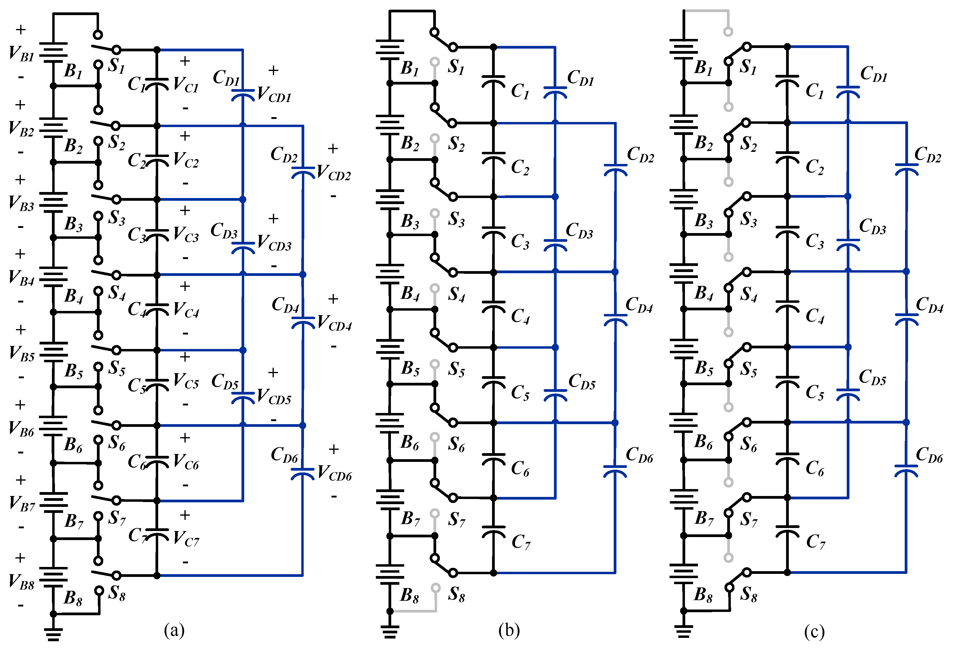
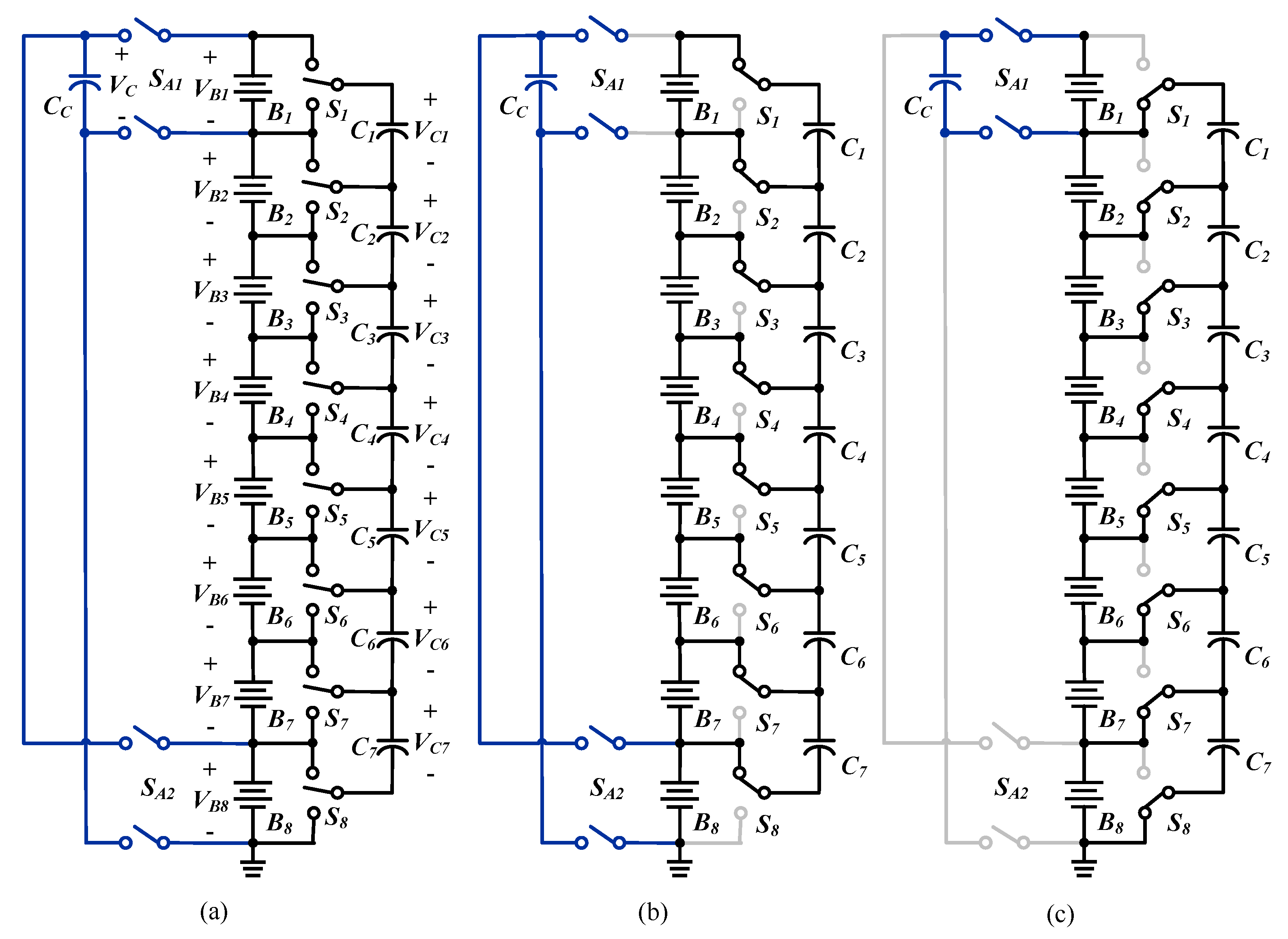
A conventional SC-based BE (type A) is shown in Figure 1a. Single-pole double-throw (SPDT) switches are utilized to connect to batteries. These SPDT switches are controlled simultaneously with a fixed switching frequency. The SPDT switches are alternately connected to the upper and lower sides with the same duty cycle and an appropriate dead time. As shown in Figure 1b,c, the operation can be divided into two states based on the switch connection. In the first state, each capacitor is placed in parallel with its corresponding upper cell; therefore, the capacitor voltage approaches the cell voltage, delivering or receiving energy from the upper cell. In the second state, the capacitors are placed in parallel with the corresponding lower cell from which energy is transferred to or from so as to reach the new voltage. After cycles of the process, energy in both cells will be balanced. The main advantages of this method are the efficiency, the potential for low- and high-power applications, and the low complexity, since no sensing or closed-loop control is needed. However, the voltage difference between adjacent cells is small in the later equalization phase and the balancing current is low, resulting in a decrease in the balancing speed [16,17].
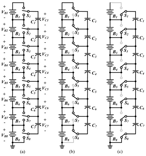
Figure 1.
Conventional SC-based BE*: (a) circuit architecture; (b) first state; (c) second state. * Eight batteries are shown as examples.
2.2. Double-Tiered SC-Based BE
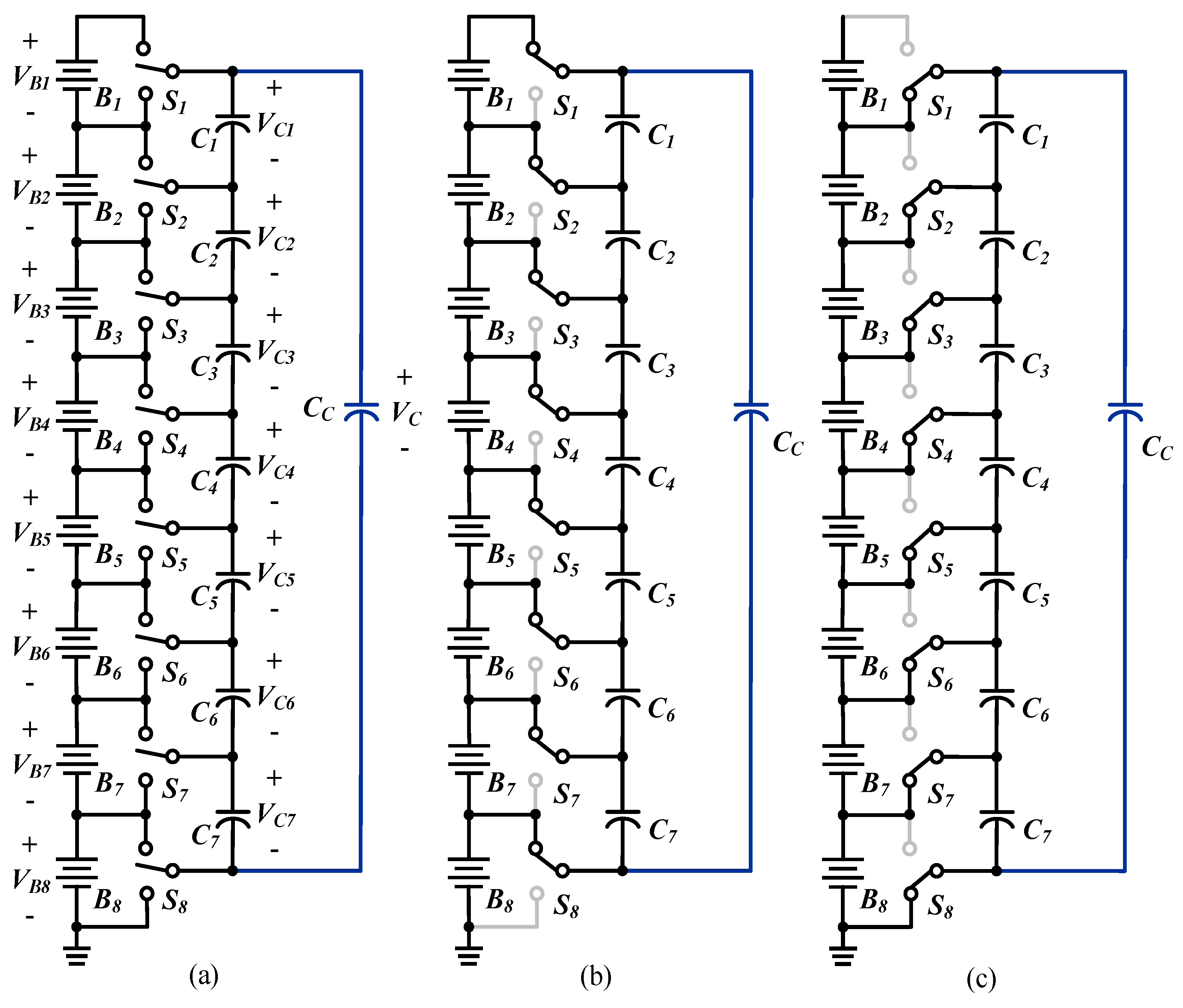
The configuration of the double-tiered SC-based BE (type B) is depicted in Figure 2. This method is similar to the conventional SC-based topology, except that it involves two tiers of capacitors to transfer energy and reduce the equalization time. In the double-tiered method, additional capacitors are added to bridge the capacitors in the first tier. With this improvement, batteries that are not directly connected through a tier 1 capacitor now have the opportunity to exchange charge via the second-tier bridging capacitors. As a result, the balancing time of the double-tiered method can be significantly reduced without major modifications of the hardware or control [18].
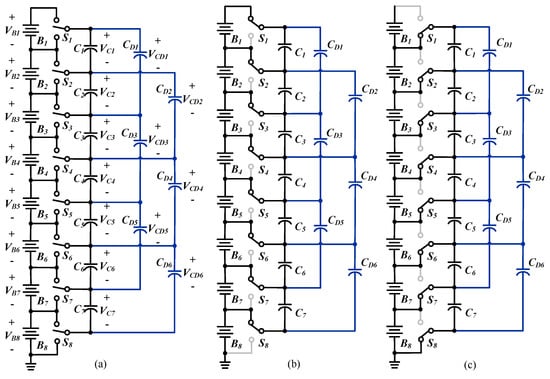
Figure 2.
Double-tiered SC-based BE*: (a) circuit architecture; (b) first state; (c) second state. * Eight batteries are shown as examples.
2.3. Modularized SC-Based BE
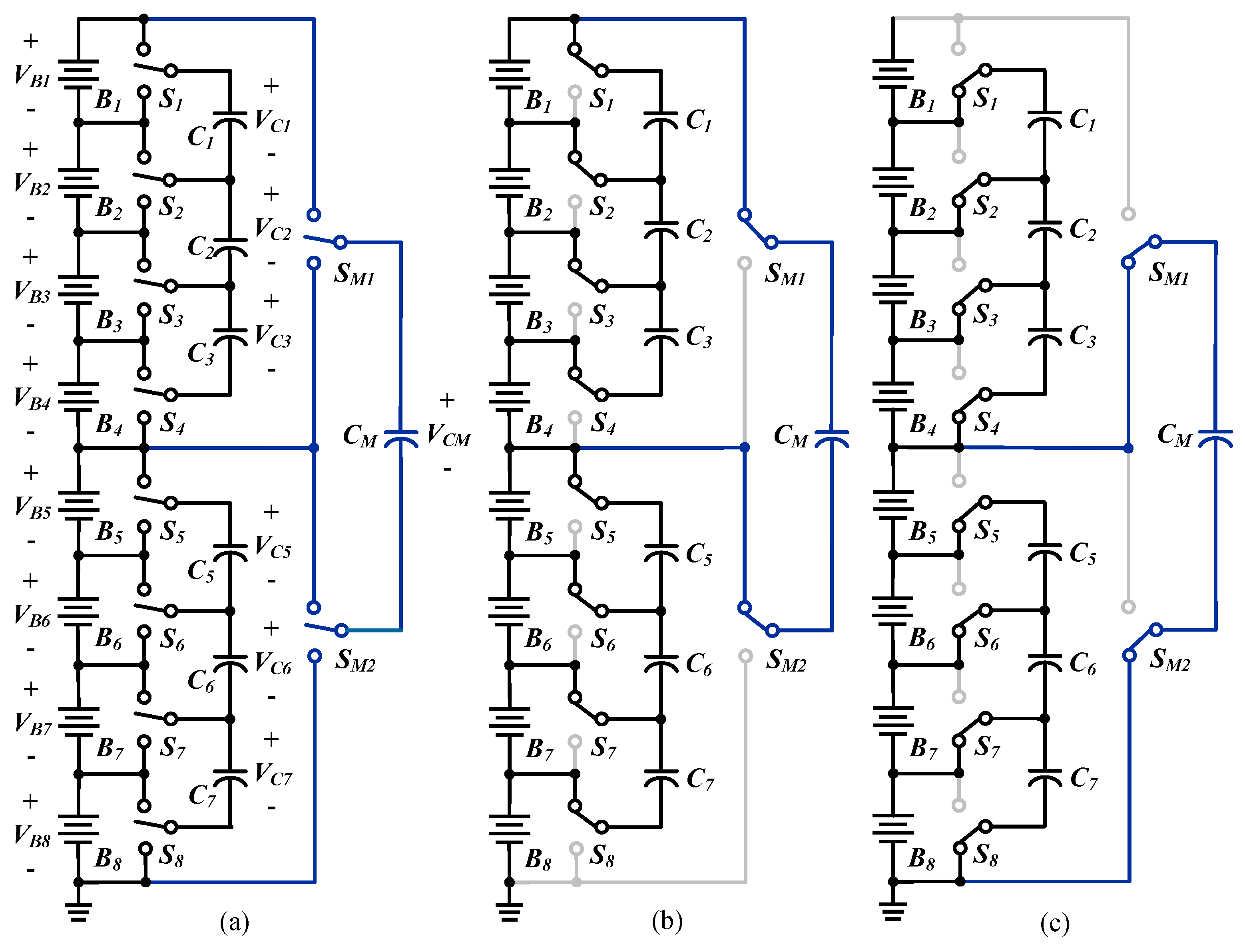
The configuration of the modularized SC-based BE (type C) is illustrated in Figure 3. The battery string is divided into multiple modules, including the inter-module and intra-module equalizers. Both of the equalizers use the switched-capacitor system. The energy transfer can be applied not only on a cell-to-cell basis, but also on a module-to-module basis in the equalizer [19].
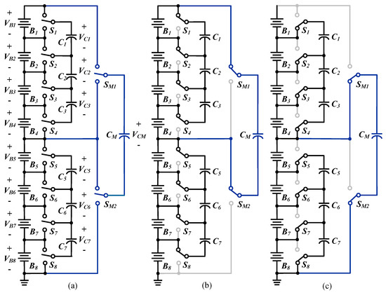
Figure 3.
Modularized SC-based BE*: (a) circuit architecture; (b) first state; (c) second state. * Eight batteries are shown as examples.
2.4. Chain Structure of SC-Based BE Type I
The configuration of the chain structure of SC-based BE type I (type D) is displayed in Figure 4. A pseudo connection is made between the uppermost and lowermost cells using additional SPDT switches and a capacitor. The distance between the farthest cells is reduced by half in this configuration. Moreover, with the chain structure, the top and bottom cells are adjacent and effective cell balancing can be achieved between the outer cells. The voltage stress of the additional capacitor is the same as that of the conventional switched capacitor. However, it is difficult to implement this structure to the large number of batteries, since the voltage stress of the additional SPDT switches is the same as the voltage of the entire battery string [20].
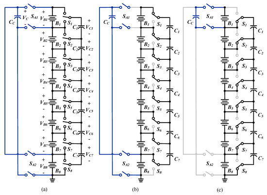
Figure 4.
Chain structure of SC-based BE type I*: (a) circuit architecture; (b) first state; (c) second state. * Eight batteries are shown as examples.
2.5. Chain Structure of SC-Based BE Type II
The configuration of the chain structure of SC-based BE type II (type E) is demonstrated in Figure 5. This configuration can handle the high voltage stress problem demonstrated in Section 2.4. An additional capacitor is paralleled to series-connected capacitors. When the voltages of the uppermost cells are different from those of the lowermost cells, the additional capacitor forms a charge transfer pathway. A pseudo-chain structure can be achieved without the use of additional switches by adding only one capacitor. The voltage stress of the additional capacitor is the same as that of the entire battery string. Since several cells are connected to form the current pathway toward the additional capacitor, the equivalent resistance of the chain increases, resulting in a slight decrease in the balancing speed [20].
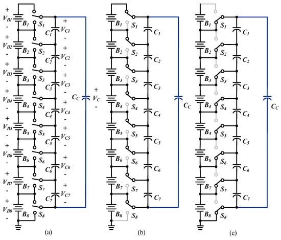
Figure 5.
Chain structure of SC-based BE type II*: (a) circuit architecture; (b) first state; (c) second state. * Eight batteries are shown as examples.
2.6. Series-Parallel SC-Based BE
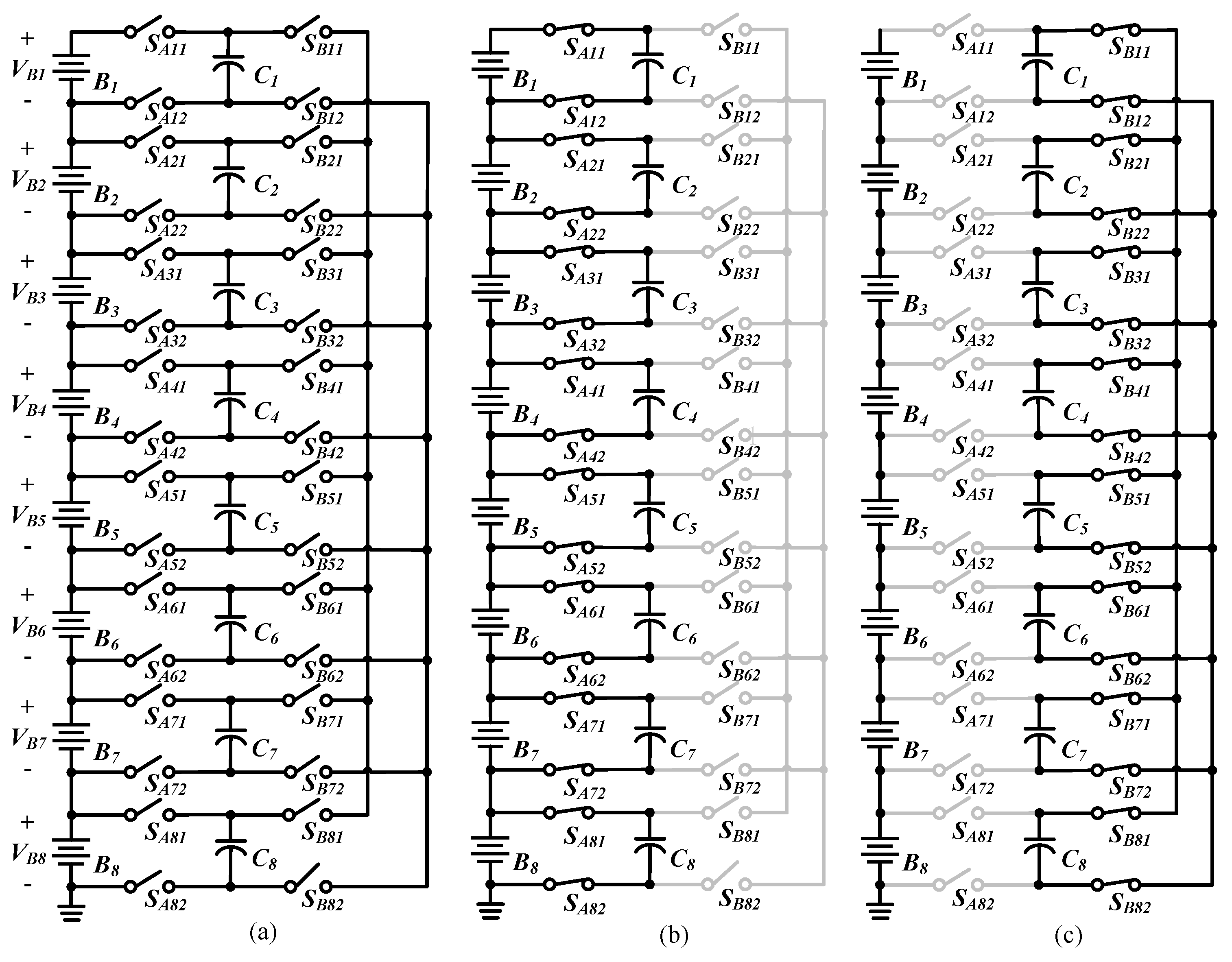
The series-parallel SC-based BE (Type F) consists of multiple SC units, as shown in Figure 6. Each SC unit is composed of a capacitor Ci and four switches, namely SAi1, SAi2, SBi1, and SBi2 (i = 1, 2, ..., n). During phase A, switches SAi1 and SAi2 are turned on concurrently, while switches SBi1 and SBi2 are turned off. As a consequence, the capacitor Ci is connected in parallel with the battery cell Bi and is charged or discharged by the battery cell, as depicted in Figure 6b. During phase B, switches SBi1 and SBi2 are turned on and switches SAi1 and SAi2 are turned off. Therefore, all of the capacitors are connected in parallel and the charge flows from the higher voltage capacitors to the lower ones, as seen in Figure 6c. The system alternately operates between these two states at a high frequency and the charge is automatically transferred from the higher voltage battery cells to the lower ones, resulting in the voltages approaching the average [21].

Figure 6.
Series-parallel SC-based BE*: (a) circuit architecture; (b) first state; (c) second state. * Eight batteries are shown as examples.
2.7. Single-SC-Based BE
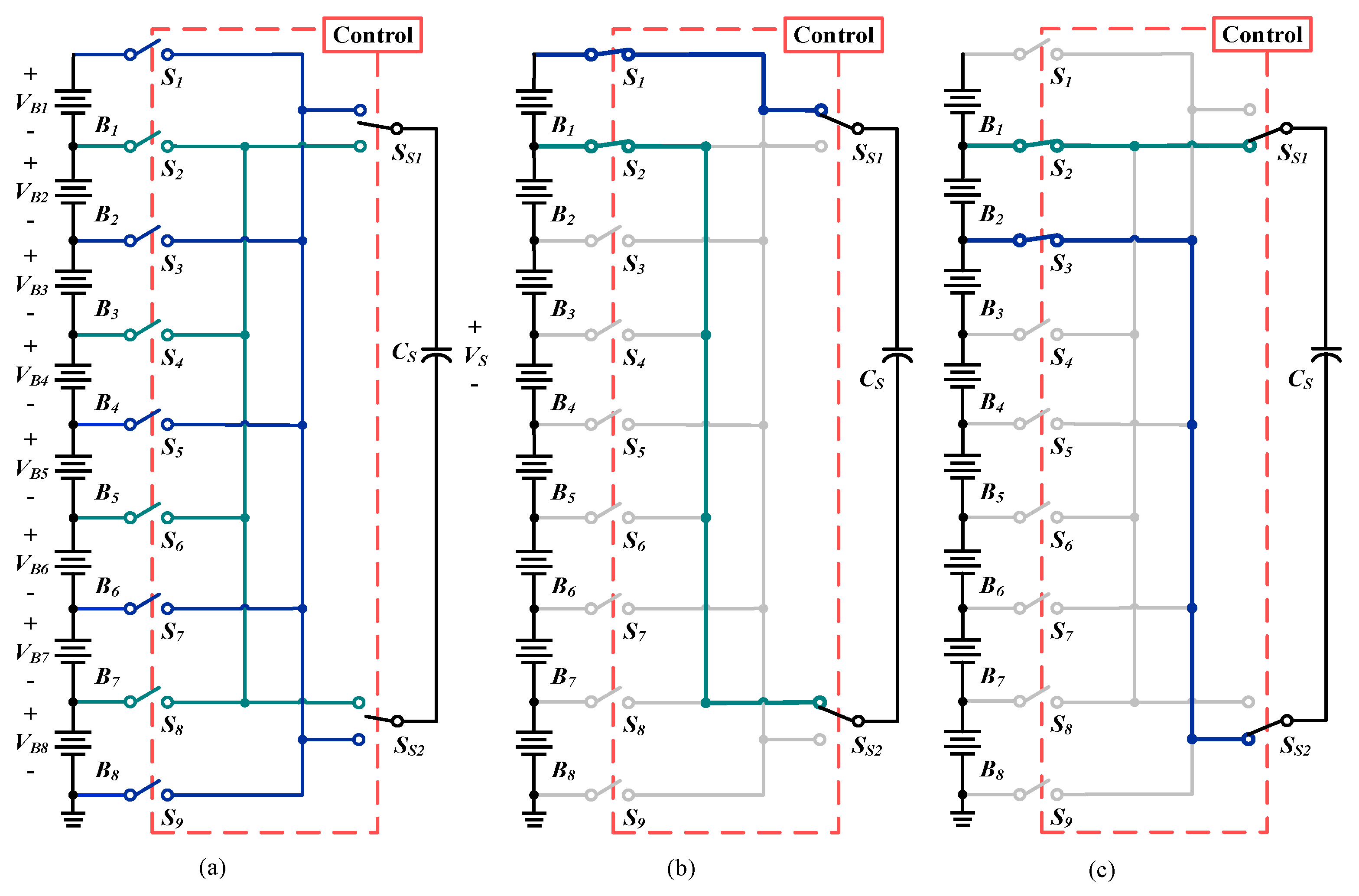
The single SC-based BE (Type G) is made up of a switch matrix and a capacitor. During the first stage, the controller selects only the switches of the highest-voltage cell so that it is in parallel with the capacitor. When the capacitor reaches the cell voltage, the controller selects only the switches of the lowest-voltage cell so that it is in parallel with the capacitor, transfer the excess energy from the capacitor to the cell. The configuration is illustrated in Figure 7. With this structure, relatively low cost and high efficiency for high-power applications can be achieved. The balancing speed is slow, since only one cell at a time is balanced [22].
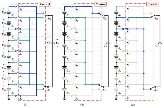
Figure 7.
Single-SC-based BE*: (a) circuit architecture; (b) first state; (c) second state. * Eight batteries are shown as examples.
2.8. Comparison of the Number of Components in Each SC-Based BE
Aside from the equalization speed, it is noteworthy that other factors such as size, cost, and efficiency should be considered in practical applications. A comparison of the numbers of components and their requirements is shown in Table 1.

Table 1.
Comparison of the number of components and their requirements for each SC-based BE.
3. Mathematical Model of the Battery Equalization System
Capacitors are used as storage and energy transfer devices in SC-based BEs. Energy is naturally transferred from a higher-voltage battery or capacitor to a lower one. Detailed descriptions of the simulated energy transfer process are provided below.
3.1. Calculation of Energy Transferred between Batteries
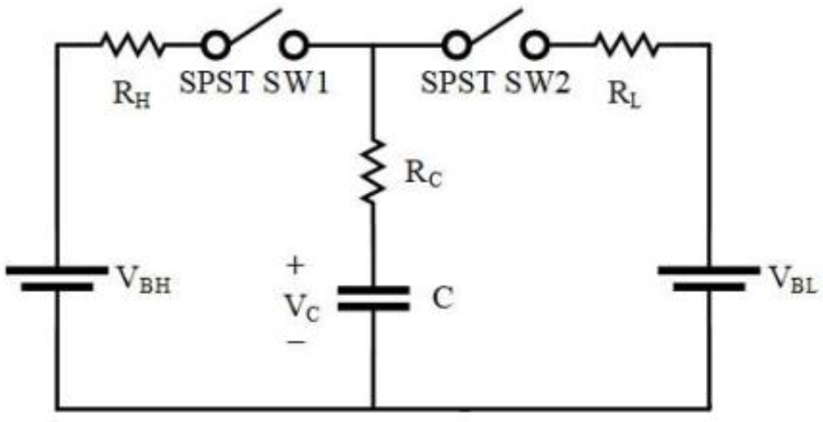
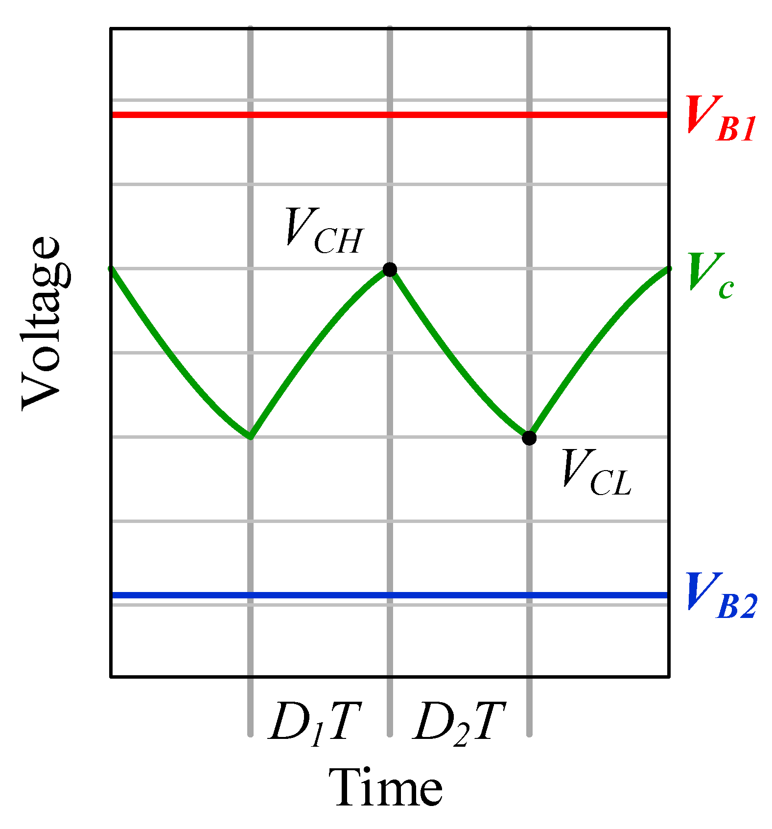
Figure 8 shows a simplified switched-capacitor converter cell. More complicated BEs generally contains n cells, each of which is topologically equivalent to this fundamental building block. Figure 9 shows the charging and discharging waveform of the capacitor voltage. In Figure 9, VBH and VBL represent batteries with higher and lower voltages, respectively. RH and RL represent the lumped resistance of the charging and discharging state, respectively. Typically, the lumped resistance includes the on-state resistance of the utilized SPDT switches, the internal resistance of the battery, and the resistance of the layouts traces. RC is the equivalent series resistance of the capacitor.
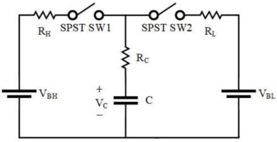
Figure 8.
Balanced circuit diagram between two batteries.

Figure 9.
Waveforms of the capacitor voltage during balancing processes.
Assuming that the operation of the SC cell has reached its steady state, the capacitor voltage can then be expressed as:
where D1 and D2 represent the duty cycle values of state 1 and state 2, respectively; τ1 and τ2 stand for the time constants of state 1 and state 2, respectively; τ1 and τ2 can be expressed as:
where Req,1 and Req,2 are the equivalent resistance of the charging and discharging states, respectively.
For SC-based BEs, the duty cycles D1 and D2 are typically the same. Additionally, the equivalent resistances are nearly equal; that is, D1 = D2 = D and τ1 = τ2 = τ. Solving Equations (1) and (2) for VCH and VCL yields:
The amount of charge supplied by the high-voltage battery to the capacitor is the same as the amount of charge transferred to the low voltage battery by the capacitor, which can be obtained using Equation (7):
Therefore, the voltage variation of the battery after one cycle can be obtained as:
It can be seen from Equation (8) that the voltage difference between the two batteries affects the energy that can be transferred per cycle. The moved energy varies continuously as the battery voltage changes during the equalization process. Using the equation above, the amount of charge transferred between the two batteries in a cycle can be calculated and the voltage change of the battery can then be obtained. It should also be noted that the on-state resistance of the utilized SPDT switches, the internal resistance of the battery, and the resistance of the layouts traces are temperature-dependent. In this study, the temperature of the operating condition is 25 °C; hence, resistance values of 25 °C are adopted for the whole study.
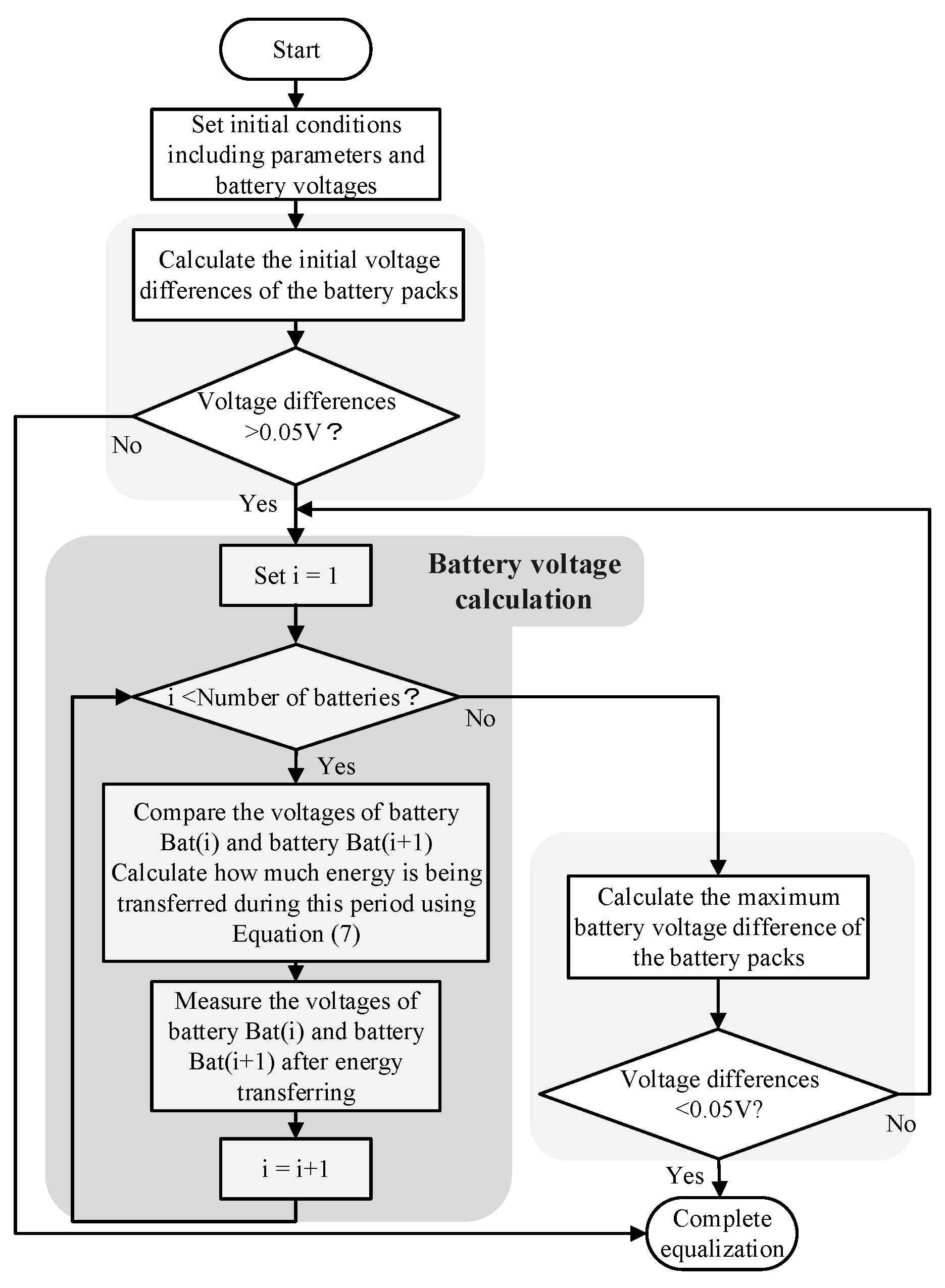
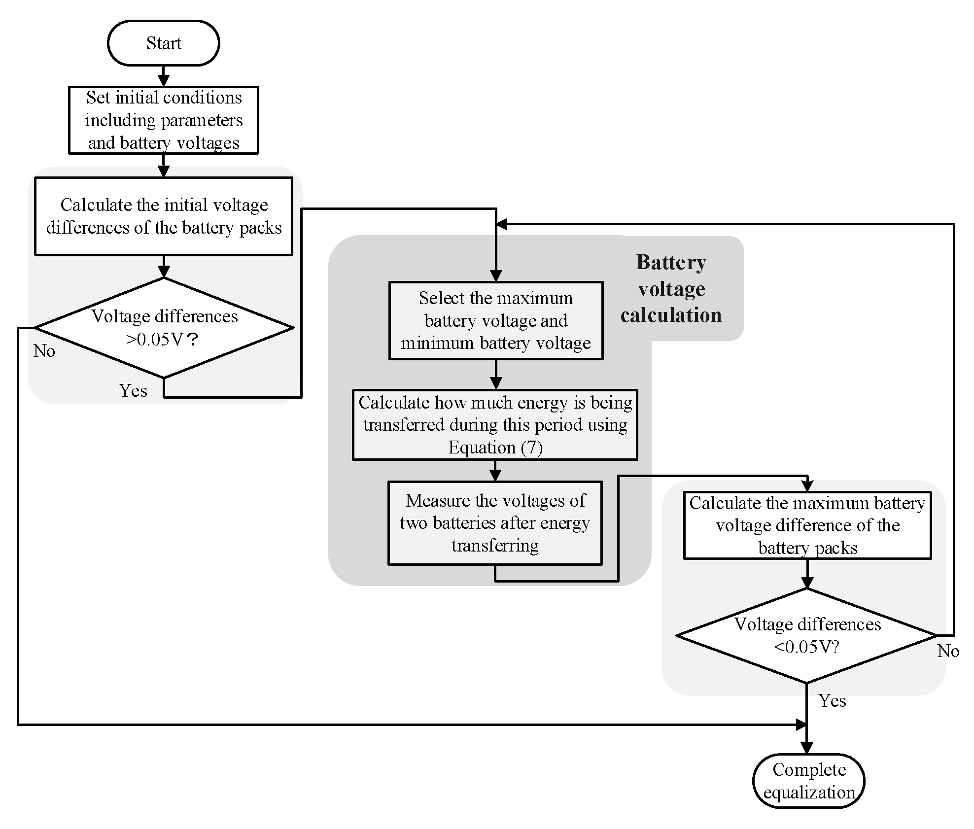
3.2. The Simulation Flow Chart of the Conventional SC-Based BE
The simulation flow chart for the conventional SC-based BE is shown in Figure 10. The parameters and the initial voltage of the batteries are set first, then the voltage difference between the batteries in the battery pack is calculated. If it is greater than the Vthreshold, it is determined that the voltage is unbalanced; hence, the battery voltage update subroutine is executed. These updates are based on the voltage difference between two adjacent batteries. The amount of charge calculated by Equations (7) and (8) is used to update the voltage of each battery. It is worth mentioning that the time constant in Equation (7) is Req*C, where Req is the total resistance in the circuit, which includes the on-resistance of the switches and the internal resistance of the batteries and the capacitors; hence, Req = RB + 2RSW + RC. After finishing a cycle, the voltage difference of all batteries is calculated again. If it is still greater than Vthreshold, the voltage update subroutine continues until a convergence criterion is met. In this way, cell balancing can be achieved.
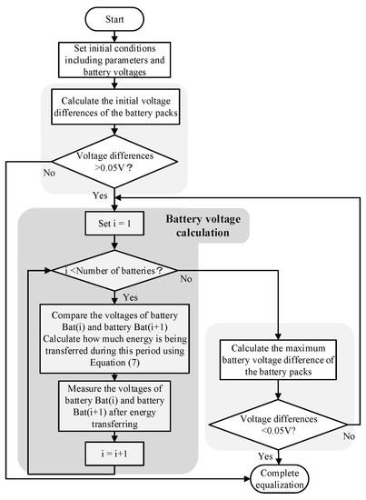
Figure 10.
Flowchart of the conventional SC-based BE.
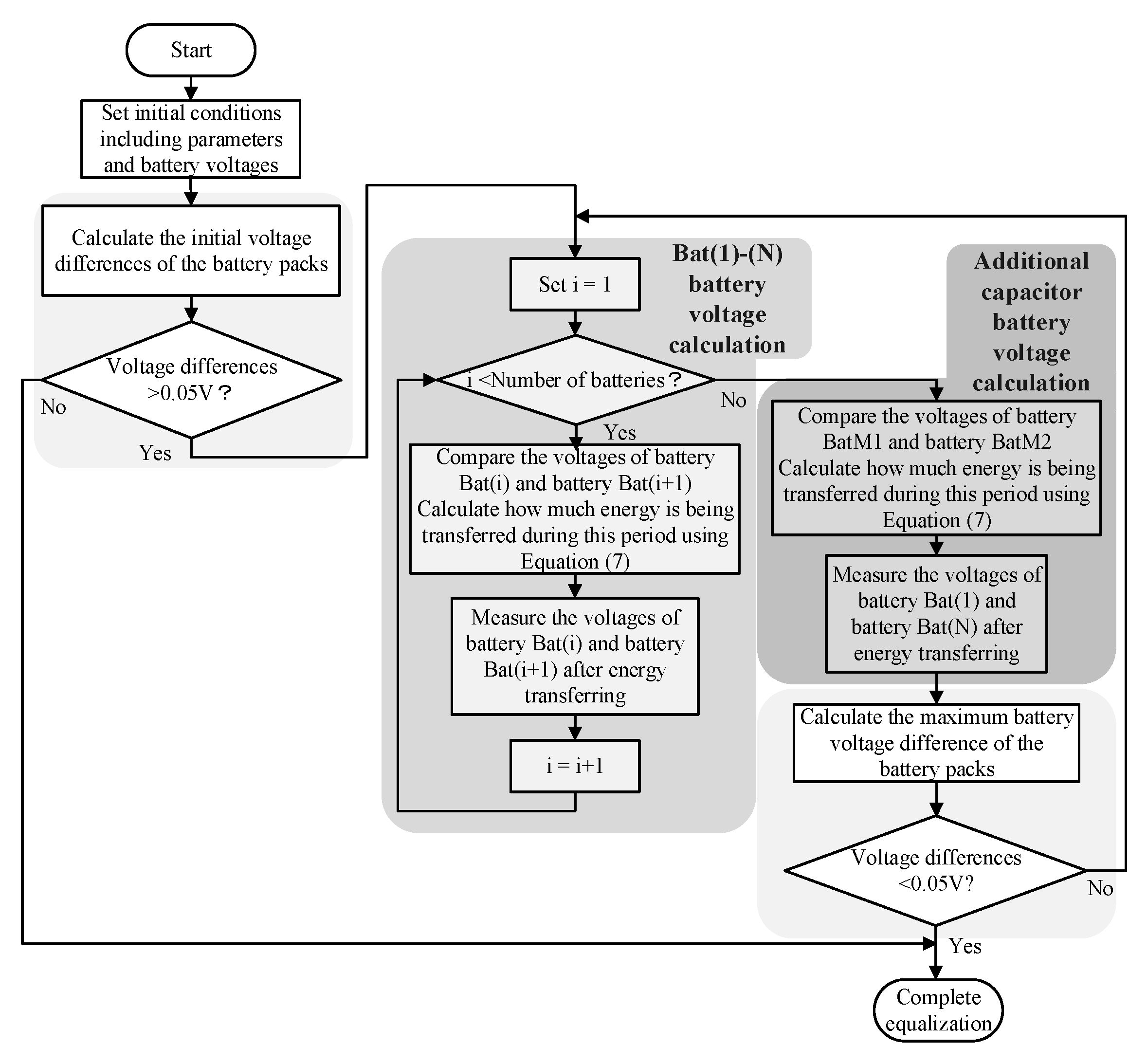
3.3. The Simulation Flow Chart of the Double-Tiered SC-Based BE
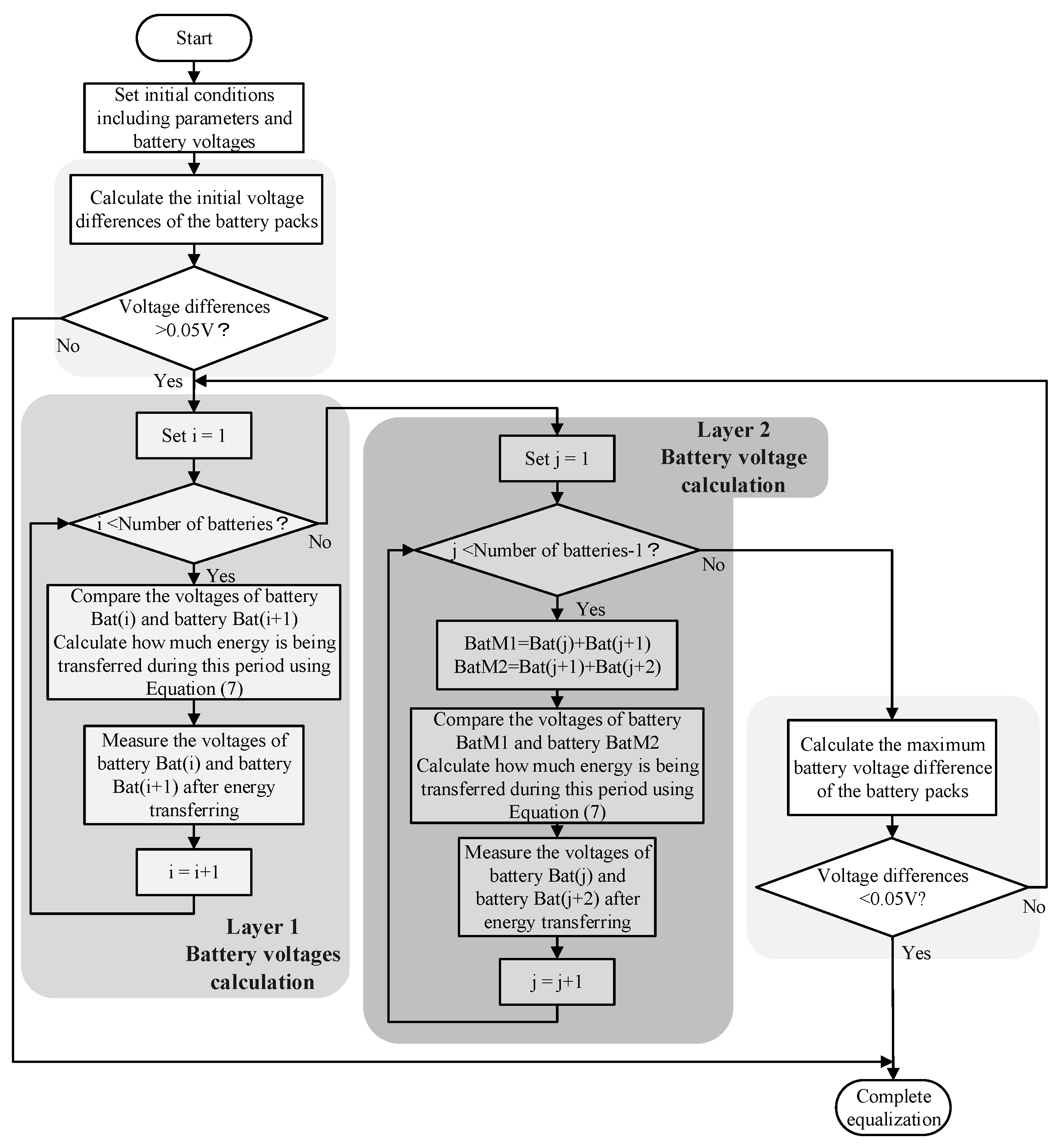
The simulation flow chart of the double-tiered SC-based BE is depicted in Figure 11. The voltage update subroutine is different from the conventional SC-based BE. It can be seen from Figure 2b,c that the additional outer capacitor can accelerate the balancing speed and that the battery packs connected in series can be balanced (e.g., CDj is responsible for the balance between VBj + VB(j+1) and VB(j+1) + VB(j+2)). Two loops are included in the voltage update subroutine. The inner loop is identical to that of the conventional SC-based BE. In the outer loop, the charge transferred between two battery packs BatM1 = VB(j) + VB(j+1) and BatM2 = VB(j+1) + VB(j+2) in a cycle can be similarly calculated by Equation (7), while the voltage is also updated by Equation (8). The inner loop resistance can be expressed as Req = RB + 2RSW + RC. It can be observed that the outer loop contains two on-resistances of the switches and the internal resistance of one capacitor and two batteries; therefore, the resistance can be expressed as Req = RB + 2RSW + RC.

Figure 11.
Flowchart of the double-tiered SC-based BE.
3.4. The Simulation Flow Chart of the Modularized SC-Based BE
The structure of the modular SC-based BE is based on the double-tiered SC-based BE and the conventional SC-based BE. It can effectively reduce the number of batteries to be connected in series, making the design easier. The balancing process is different from the conventional SC-based BE. As seen in Figure 3a, additional capacitors are added between battery packs to provide an energy transfer path between them. These capacitors perform voltage balancing of the two battery packs in a cycle. The voltage update loops include the inner and outer loops, which are similar to those of the double-tiered SC-based BE. The charge that is moved between the two battery packs in a cycle can also be calculated using Equation (7), while the voltage is updated by Equation (8). The inner loop is similar to the conventional SC-based BE and the resistance can also be expressed as Req = NmnRB + 2RSW + RC. The number of batteries in a module, the internal resistance of the capacitors, and the on-resistance of the switches should be considered for the outer loop, as shown in Figure 12. If the number of batteries in a battery pack is Nmn, the resistance can be expressed as Req = NmnRB + 2RSW + RC.
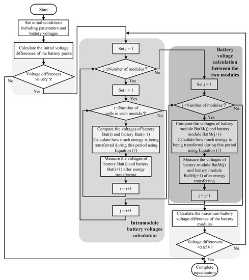
Figure 12.
Flowchart of the modularized SC-based BE.
3.5. The Simulation Flow Chart of the Chain Structure of SC-Based BE Type I
The simulation flow chart of the chain structure of SC-based BE type I is demonstrated in Figure 13. An additional energy transfer path is added between the top and the bottom of the battery string, allowing energy to be transferred from battery 1 to battery N. The energy transfer path is shortened and the energy loss can be reduced. The simulation program is the same as the conventional one, in which the moved charge and updated voltage are obtained using Equations (7) and (8), respectively. The Req is the total resistance of the energy transfer path, which contains the on-resistance of the switches and the internal resistance of the capacitors and the two batteries; thus, Req = RB+ 2Rsw+ RC.
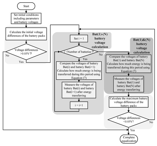
Figure 13.
Flowchart of the chain structure of SC-based BE type I.
3.6. The Simulation Flow Chart of the Chain Structure of SC-Based BE Type II
Additional capacitors are used to deal with the switch stress problem in the chain structure of SC-based BE type I. The simulation flow chart of the chain structure of SC-based BE type II is illustrated in Figure 14. Since the added capacitor is paralleled with n − 1 batteries, the internal resistance values of the batteries, switches, and capacitors need to be considered; therefore, Req = (n − 1)RB+ 2RSW+ RC.

Figure 14.
Flowchart of the chain structure of SC-based BE type II.
3.7. The Simulation Flow Chart of the Series-Parallel SC-Based BE
In this structure, a pair of PWM signals is required, as well as the conventional topology, while one capacitor and four switches are required for the battery. The simulation flow chart of the series-parallel SC-based BE is displayed in Figure 15. It is assumed that when the switch is turned on, n capacitors are connected in parallel. After balancing, the voltage of n capacitors is the same due to a lower time constant. The voltage of each battery is then calculated by comparing the voltage of the batteries Bat(i) with the capacitors so that the transferred charge can be obtained. The total resistance Req of the transfer path is RB + 2RSW + RC.
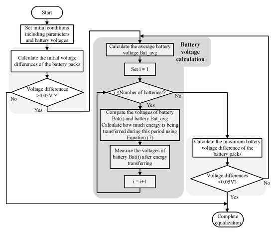
Figure 15.
Flowchart of the series-parallel SC-based BE.
3.8. The Simulation Flow Chart of the Modularized SC-Based BE
Only one capacitor and n + 5 switches are required in this topology. The simulation flow chart of the single SC-based BE is shown in Figure 16. In the voltage update subroutine, the highest voltage and the lowest voltage in the battery pack are selected. The corresponding switches are controlled to connect the battery and the capacitor in parallel so that the energy can be transferred between these two batteries; hence, the transferred charge in a cycle can be calculated. The equivalent resistance Req is RB + 2RSW + RC. The voltage update subroutine keeps going until the batteries are balanced.
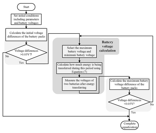
Figure 16.
Flowchart of the single SC-based BE.
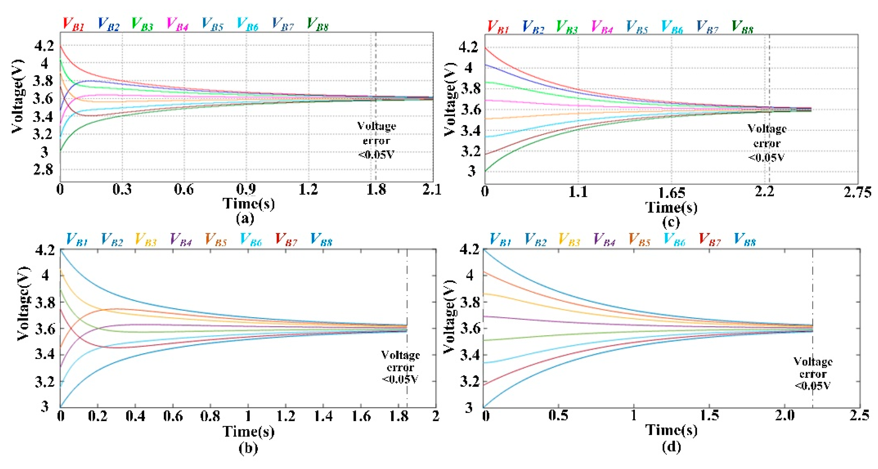
3.9. Validation of the Simulation Platform
Section 3.2, Section 3.3, Section 3.4, Section 3.5, Section 3.6, Section 3.7 and Section 3.8 describe the flow charts of the compared SC-based topologies. However, the correctness of the developed flowcharts should be confirmed so that the validity of the performance evaluation can be guaranteed. In this study, the correctness of the derived flow chart is substantiated using the commercially available simulation software PSIM from Powersim Corp. In this study, the SC-based BEs are implemented in both MATLAB and PSIM and their equalization process is demonstrated using lithium-ion (Li-ion) batteries. The Li-ion battery has an operating voltage range of 3.0 V to 4.2 V and an equivalent capacitance of several thousand farads. To shorten the simulation time, the equivalent capacitance of the battery cell is set to 1 F while other parameters remain the same, which are listed in Table 2. Two different ICs are designed for simulation, which are (1) different initial voltages in a random order and (2) different initial voltages sorted into a sequence from high to low. The details of these two simulation scenarios are given in Table 3. Figure 17 shows the simulated results of the double-tiered SC-based BE obtained from the proposed simulation platform and the PSIM software. As shown in Figure 17, the voltage waveform obtained from the proposed simulation platform is consistent with the PSIM simulation.
Table 2.
Simulation parameters.
Table 3.
Two simulation scenarios for different ICs.
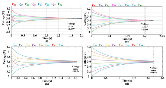
Figure 17.
Voltage curves of double-tiered SC-based BE during equalization: (a) scenario 1 using PSIM; (b) scenario 1 using MATLAB; (c) scenario 2 using PSIM; (d) scenario 2 using MATLAB.
4. Analysis and Comparison of Balancing Performance
This paper aims to investigate the balancing performance of SC-based BEs. Unlike previous studies where only certain ICs were considered, this paper discusses the balancing performance in terms of different cell numbers and varied ICs. In this paper, 7 types of SC-based BEs are simulated on the same platform. Compared with circuit simulation software such as PSIM, the proposed simulation platform is capable of reducing the simulation time and further accelerating the analysis of the balancing efficiency under various ICs in a short time. In addition, a Monte Carlo statistical study similar to [23] is carried out in this paper to compare these seven SC-based topologies. The Monte Carlo simulation is performed with equalizers for 4 battery cells and 8 battery cells. The obtained results are given in Section 4.1 and Section 4.2, respectively, and the discussion of these results is presented in Section 4.3.
4.1. Equalization Results for Four Battery Cells
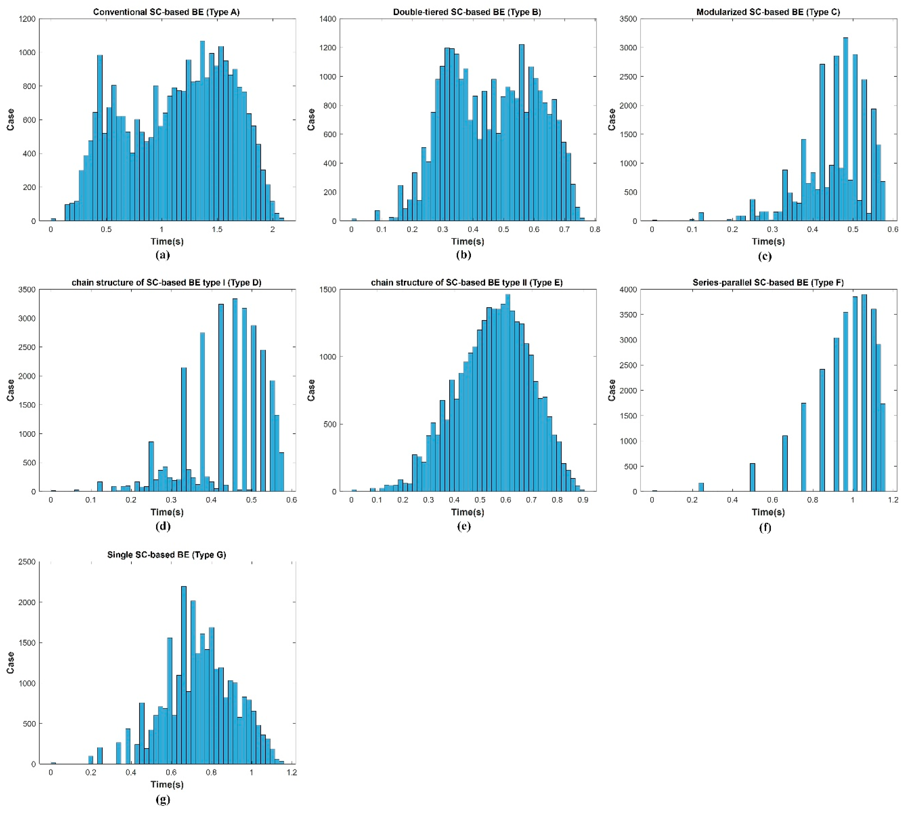
With voltage variations in intervals of 0.1 V, there are 13 possible values for a Li-ion cell’s voltage, i.e., 4.2 V, 4.1 V, 4.0 V, …, 3.1 V, and 3.0 V. Therefore, there are a total of 134 = 28,561 possible combinations of the ICs for 4 series-connected battery cells. In this study, four sets of 500 simulation cases are firstly generated randomly and independently according to uniform distribution U(0, 1). Next, all possible simulation cases are enumerated and simulated for comparison. Table 4 illustrates the obtained results. It can be observed that the error between the 500 simulation cases and all possible cases is lower than 1%, which indicates that the 500 ICs can represent the simulation results for all possible simulation cases based on Monte Carlo simulation. To further verify the results obtained from the Monte Carlo simulation, a histogram of the balancing time for all 28,561 scenarios is given in Figure 18. It can be observed that the balancing time distribution corresponds to the results shown in Table 4.
Table 4.
Average balancing times of the 4 battery cells using different SC-based BEs.
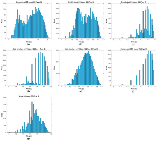
Figure 18.
Histogram of the balancing times for all 28,561 cases for 4 battery cells: (a) type A; (b) type B; (c) type C; (d) type D; (e) type E; (f) type F; (g) type G.
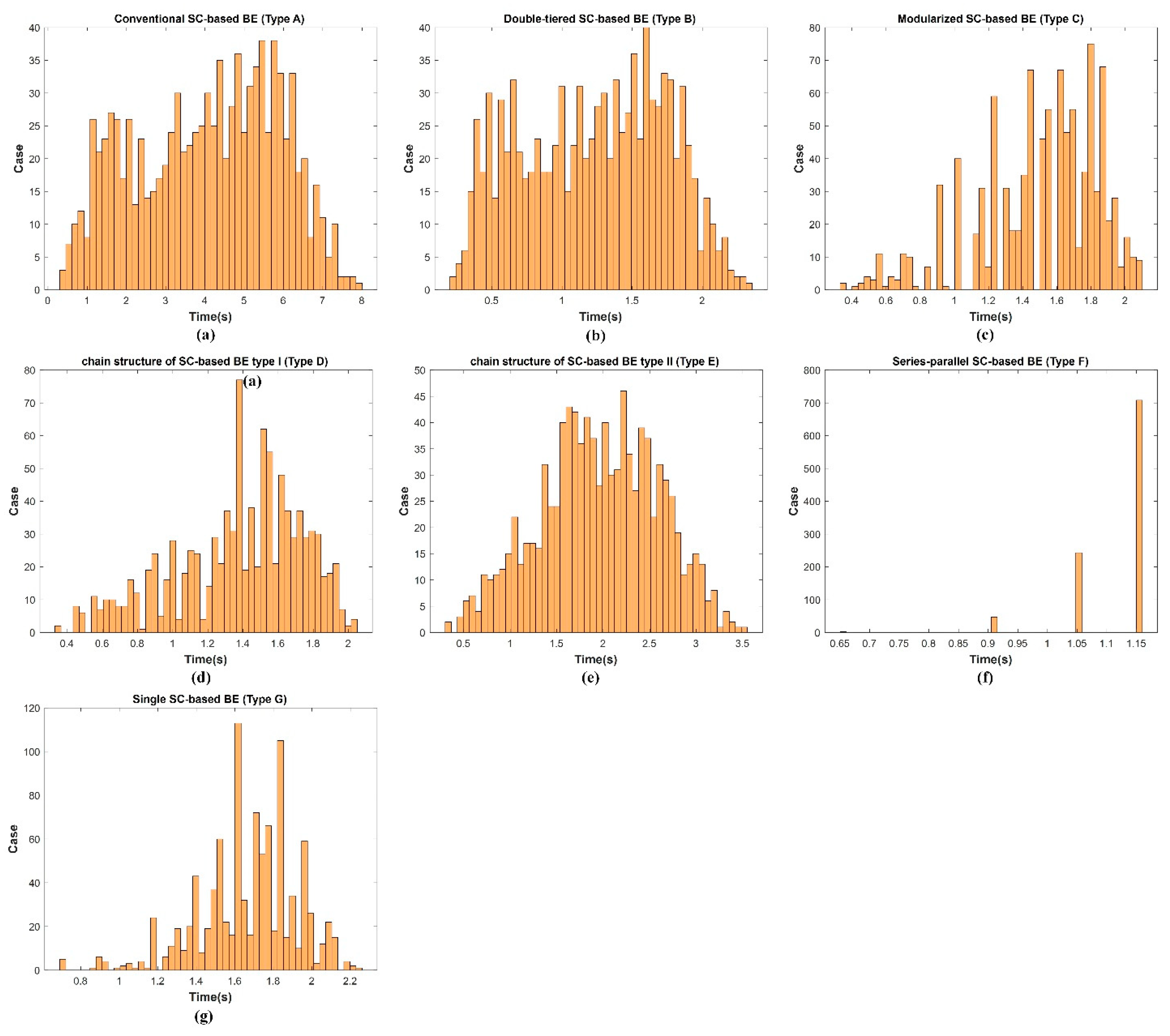
4.2. Equalization Results for Eight Battery Cells
Given an 8-series-connected battery cell, there are 138 possible combinations of ICs. As this is a huge number of possible ICs, it is not practical to replicate all of the possible scenarios to assess their balancing performance. Therefore, three independent Monte Carlo simulations with 1000 cases are adopted in this study, and the obtained results in terms of averaged balancing times are listed in Table 5. According to Table 5, the balancing time errors for 1000 combinations of ICs are all lower than 1.6%. In other words, the simulation results for 1000 combinations of ICs can be regarded as representing all of the possible combinations of ICs. Similarly, a histogram of the balancing time for the first 1000 cases is given in Figure 19.
Table 5.
Average balancing times of 8 battery cells using different SC-based BEs.

Figure 19.
Histogram of the balancing times for the first 1000 cases (case 1) for 8 battery cells: (a) type A; (b) type B; (c) type C; (d) type D; (e) type E; (f) type F; (g) type G.
4.3. Analysis of the Balancing Performance for Different Numbers of Battery Cells
Table 6 summarizes the obtained results. As shown in Table 6, when the number of batteries increases from 4 to 8, the series-parallel structure requires almost the same number of energy transfer steps, irrespective of the number of battery cells; thus, the balancing time of the series-parallel structure increases slightly. There is not much difference in the balance times between the double-layer structure, modularized structure, and chain structure type I. The double-layer structure has more power transfer paths compared with chain structure type I; thus, the double-layer structure is more advantageous when there are more battery cells. Although chain structures types I and II have similar power transfer paths, the additional equivalent series resistance of the external paths means chain structure type II has a slower balancing speed. The single-SC structure has only one energy transfer path at a time. Hence, the balancing time cannot be shortened. The conventional SC structure has the fewest power transfer paths, meaning it has the slowest balancing speed. As a result, it can be forecasted that when the number of battery cells increases, the balancing time of the series-parallel structure should still be the shortest, while the balancing times for the double-layer structure, modularized structure, and chain structure type I would be very close and their performance ranking may change according to the ICs. It takes a rather long time to balance the single-SC structure, chain structure type II, and the conventional structure.
Table 6.
Averaged balancing times for 4 and 8 cells and their rankings when using different equalization structures.
Apart from the balancing time, it is also essential to consider a number of components such as the rated voltage, rated current, and cost when determining the appropriate BE. Please refer to Table 1 for more detailed information for SC-based BEs.
5. Conclusions
This paper has proposed a simulation platform based on a mathematical model of SC-based BEs to deal with the heavy computation and time-consuming problems involved when using circuit simulation software. The proposed simulation approach calculates the energy transferred in every cycle to ensure the accuracy of the simulated results. Seven SC-based BEs were implemented in MATLAB software. The results of balancing time were compared for 4 and 8 series-connected batteries under different ICs. The proposed simulation platform can efficiently estimate the balancing times for SC-based BEs when the number of battery cells is different or when the ICs are varied. In particular, the proposed simulation platform is helpful for evaluating the balancing performance and determining the appropriate SC-based BEs according to the application.
Author Contributions
Conceptualization, K.-C.H. and Y.-H.L.; methodology, K.-C.H. and G.-J.C.; software, S.-P.Y.; validation, K.-C.H., Y.-S.C. and Y.-H.L.; writing—original draft preparation, Y.-H.L.; writing—review and editing, Y.-H.L. All authors have read and agreed to the published version of the manuscript.
Funding
This work was partially supported by the Delta–NTUST Joint Research Center.
Acknowledgments
This work was partially supported by the Delta–NTUST Joint Research Center in Taiwan. The authors are grateful for the funding provided by the Delta-NTUST Joint Research Center.
Conflicts of Interest
The authors declare no conflict of interest.
References
- Ouyang, Q.; Wang, Z.; Liu, K.; Xu, G.; Li, Y. Optimal charging control for lithium-ion battery packs: A distributed average tracking approach. IEEE Trans. Ind. Inform. 2019, 16, 3430–3438. [Google Scholar] [CrossRef]
- Gao, Y.; Zhang, X.; Guo, B.; Zhu, C.; Wiedemann, J.; Wang, L.; Cao, J. Health-Aware Multiobjective Optimal Charging Strategy With Coupled Electrochemical-Thermal-Aging Model for Lithium-Ion Battery. IEEE Trans. Ind. Inform. 2019, 16, 3417–3429. [Google Scholar] [CrossRef]
- Xiong, R.; Yang, R.; Chen, Z.; Shen, W.; Sun, F. Online fault diagnosis of external short circuit for lithium-ion battery pack. IEEE Trans. Ind. Electron. 2019, 67, 1081–1091. [Google Scholar] [CrossRef]
- Lu, X.; Wang, H. Optimal sizing and energy management for cost-effective PEV hybrid energy storage systems. IEEE Trans. Ind. Inform. 2019, 16, 3407–3416. [Google Scholar] [CrossRef]
- Ding, L.; Han, Q.L.; Ning, B.; Yue, D. Distributed resilient finite-time secondary control for heterogeneous battery energy storage systems under denial-of-service attacks. IEEE Trans. Ind. Inform. 2019, 16, 4909–4919. [Google Scholar] [CrossRef]
- Chekired, D.A.; Khoukhi, L.; Mouftah, H.T. Fog-Computing-Based Energy Storage in Smart Grid: A Cut-Off Priority Queuing Model for Plug-In Electrified Vehicle Charging. IEEE Trans. Ind. Inform. 2019, 16, 3470–3482. [Google Scholar] [CrossRef]
- Yang, Y.D.; Hu, K.Y.; Tsai, C.H. Digital Battery Management Design for Point-of-Load Applications with Cell Balancing. IEEE Trans. Ind. Electron. 2019, 67, 6365–6375. [Google Scholar] [CrossRef]
- Zahedmanesh, A.; Muttaqi, K.M.; Sutanto, D. A Sequential Decision-Making Process for Optimal Techno-Economic Operation of a Grid Connected Electrical Traction Substation Integrated with Solar PV and BESS. IEEE Trans. Ind. Electron. 2020, 68, 1353–1364. [Google Scholar] [CrossRef]
- Ouyang, Q.; Han, W.; Zou, C.; Xu, G.; Wang, Z. Cell Balancing Control For Lithium-Ion Battery Packs: A Hierarchical Optimal Approach. IEEE Trans. Ind. Inform. 2019, 16, 5065–5075. [Google Scholar] [CrossRef]
- Vulligaddala, V.B.; Vernekar, S.; Singamla, S.; Adusumalli, R.K.; Ele, V.; Brandl, M.; Srinivas, M.B. A 7-Cell, Stackable, Li-Ion Monitoring and Active/Passive Balancing IC With In-Built Cell Balancing Switches for Electric and Hybrid Vehicles. IEEE Trans. Ind. Inform. 2019, 16, 3335–3344. [Google Scholar] [CrossRef]
- Shang, Y.; Zhao, S.; Fu, Y.; Han, B.; Hu, P.; Mi, C.C. A Lithium-ion battery balancing circuit based on synchronous rectification. IEEE Trans. Power Electron. 2019, 35, 1637–1648. [Google Scholar] [CrossRef]
- Raeber, M.; Heinzelmann, A.; Abdeslam, D.O. Analysis of an active charge balancing method based on a single non-isolated DC/DC converter. IEEE Trans. Ind. Electron. 2021, 68, 2257–2265. [Google Scholar] [CrossRef]
- Zhang, H.; Wang, Y.; Qi, H.; Zhang, J. Active battery equalization method based on redundant battery for electric vehicles. IEEE Trans. Veh. Technol. 2019, 68, 7531–7543. [Google Scholar] [CrossRef]
- Narayanaswamy, S.; Steinhorst, S.; Lukasiewycz, M.; Kauer, M.; Chakraborty, S. Optimal Dimensioning and Control of Active Cell Balancing Architectures. IEEE Trans. Veh. Technol. 2019, 68, 9632–9646. [Google Scholar] [CrossRef]
- Gallardo-Lozano, J.; Romero-Cadaval, E.; Milanes-Montero, M.I.; Guerrero-Martinez, M.A. Battery equalization active methods. J. Power Sources 2014, 246, 934–949. [Google Scholar] [CrossRef]
- Pascual, C.; Krein, P.T. Switched capacitor system for automatic series battery equalization. In Proceedings of the IEEE Annual Applied Power Electronics Conference and Exposition (APEC), Atlanta, GA, USA, 27 February 1997; pp. 848–854. [Google Scholar]
- Kobzev, G.A. Switched-capacitor systems for battery equalization. In Proceedings of the IEEE International Scientific and Practical Conference of Students, Post-graduates and Young Scientists. Modern Techniques and Technology, Tomsk, Russia, 3 March 2000; pp. 57–59. [Google Scholar]
- Baughman, A.C.; Ferdowsi, M. Double-tiered switched-capacitor battery charge equalization technique. IEEE Trans. Ind. Electron. 2008, 55, 2277–2285. [Google Scholar] [CrossRef]
- Park, H.S.; Kim, C.H.; Park, K.B.; Moon, G.W.; Lee, J.H. Design of a charge equalizer based on battery modularization. IEEE Trans. Veh. Technol. 2009, 58, 3216–3223. [Google Scholar] [CrossRef]
- Kim, M.Y.; Kim, C.H.; Kim, J.H.; Moon, G.W. A chain structure of switched capacitor for improved cell balancing speed of lithium-ion batteries. IEEE Trans. Ind. Electron. 2013, 61, 3989–3999. [Google Scholar] [CrossRef]
- Ye, Y.; Cheng, K.W.E. Modeling and analysis of series–parallel switched-capacitor voltage equalizer for battery/supercapacitor strings. IEEE J. Emerg. Sel. Top. Power Electron. 2015, 3, 977–983. [Google Scholar] [CrossRef]
- Daowd, M.; Antoine, M.; Omar, N.; Van den Bossche, P.; Van Mierlo, J. Single switched capacitor battery balancing system enhancements. Energies 2013, 6, 2149–2174. [Google Scholar] [CrossRef] [Green Version]
- Chen, H.; Zhang, L.; Han, Y. System-theoretic analysis of a class of battery equalization systems: Mathematical modeling and performance evaluation. IEEE Trans. Veh. Technol. 2015, 64, 1445–1457. [Google Scholar] [CrossRef]


Publisher’s Note: MDPI stays neutral with regard to jurisdictional claims in published maps and institutional affiliations. |
© 2021 by the authors. Licensee MDPI, Basel, Switzerland. This article is an open access article distributed under the terms and conditions of the Creative Commons Attribution (CC BY) license (https://creativecommons.org/licenses/by/4.0/).