Abstract
This paper proposes a hybrid beamforming design algorithm for a multi-user physical layer security modulation technique. The hybrid beamforming scheme is used in the base station to generate multi-beams according to the direction angle of the target users. The base station first uses a secure analog beamforming scheme to generate analog beams in multiple desired directions, then uses minimum mean square error (MMSE) to design the digital beamforming matrix to eliminate inter-beam interference. Due to randomly selecting a subset of antennas to transmit signals at the symbol rate, the base station transmits the defined constellation to the target users and projects the randomized constellation in the other angles. In addition, the superposition of signals is affected by a randomly selected antennas subset, resulting in higher sidelobe energy. However, due to the integer optimization target, the optimization problem of antenna subsets is non-trivial. Therefore, this paper proposes a cross-entropy iteration method to choose the optimal antenna combination to reduce the sidelobe energy. The simulation shows that the proposed method in this paper has about 10 dB lower sidelobe energy than the random selection method. Besides, the eavesdropper’s symbol error rate of QPSK is always 0.75, while the multi-target users meet the quality of service requirements.
1. Introduction
With the explosive growth of the commercial communication services, such as virtual reality and vision-based sensors [1,2,3,4,5,6], it is required to support a large number of low-latency and high-speed interconnection devices in 6G communication networks, which is difficult to achieve in low frequency bands. Therefore, millimeter wave (mmWave) band has become a natural choice to implement the high data rate transmission [7,8,9,10]. In addition, due to the high speed and frequent information exchange, each connected device also faces the problem of secure communication [11]. The source encryption and decryption is mainly adopted by the existing secure communication solutions, which has high complexity and huge resource consumption, resulting in a waste of resources in the entire system. The physical layer security (PLS) transmission technology uses the randomness of the wireless channel to achieve better secure transmission with low resource occupation [12,13,14,15].
The beamforming design for physical layer security communication has been studied by some literature, recently. Specifically, W. Zhang et al. have proposed an artificial-noise-aided optimal beamforming scheme to minimize the transmit power at the base station, while meeting the minimum secrecy rate requirements of all secret messages [16]. The beamforming design scheme of optimal power allocation between the information-bearing signal and the artificial noise signal is introduced in [17] to enhance the physical layer security. J. Song et al. have proposed a beamforming scheme to maximizes the secrecy rate of the desired user to enhance the physical layer security in dual-polarized millimeter wave systems [18]. A transmit zero forcing beamforming technique and the optimum power allocation algorithms have been studied in [19] to improve the physical layer security for multiple-input multiple-output non-orthogonal multiple access system. All the above literature has analyzed the system secure performance such as the secrecy rate and outage probability. In terms of the physical layer of security modulation technology, the deep nulls can be formed in the direction of the eavesdroppers to suppress the data reception and copying with the precise knowledge of channel state information [20]. However, the channel state of an eavesdropper is difficult to obtain because of the non-cooperation of eavesdroppers, so the deep null method is not practical. On the other hand, when the channel state of an eavesdropper is unknown, the transmitter sends data in the direction of the target user and the artificial noise in other directions [21,22,23]. Due to using part of the power to transmit noise, the power of the target signal is reduced, resulting in a decrease in the system’s energy efficiency.
Physical layer security modulation techniques, such as directional modulation, which is shown in Table 1, transmit a defined constellation diagram in the direction of a target user, and transmit a noise pattern in other directions, which has been extensively studied in millimeter wave communication systems. The authors of [24] have proposed a low-complexity directional modulation technique, which can modulate the radiation pattern by selecting an antenna subset randomly for every symbol. The authors of [25] have introduced switched phased-array transmission architecture, which consists of a conventional phased-array followed by antennas with a switch circuit to enhance physical layer security. Furthermore, a new scheme of optimized weight antenna subset transmission techniques based on programmable weight phased array architecture has been proposed in [26], which generates more artificial noise than conventional schemes in the undesired directions. Moreover, the authors of [27] have proposed a secure transmission algorithm by varying the transmitting weight vector at symbol rate based on the aid of polygon construction in the complex plane.

Table 1.
The comparison of physical layer modulation technology.
Due to the multiple transmission paths in the multi-user system, multiple security beams need to be generated at the same time to transmit data. However, the analog arrays used by the above mentioned secure transmission schemes can only be applied to a single target user scenario. Besides, it is hard to realize the fully-digital processing at millimeter wave frequencies with wide bandwidths and large antenna arrays because of the high cost and power consumption with mixed-signal components such as high-resolution analog to digital converters. Therefore, the hybrid beamforming scheme is adopted to service multiple users in this paper.
To our best knowledge, we first propose the hybrid beamforming for multi-user physical layer security modulation techniques. In addition, we also propose cross-entropy to optimize the sidelobe energy, which makes the energy of an eavesdropper lower to further enhance the secure performance. Our simulation results demonstrate that the transmission structure can achieve a better multi-user physical layer security performance with lower sidelobe energy than the traditional schemes.
This paper is organized as follows: the introduction is given in Section 1. In Section 2, the system model is introduced. The CE-based analog beamforming scheme is given in Section 3. The CE-based multi-user hybrid beamforming scheme is discussed in Section 4. The simulation results are presented in Section 5. A conclusion and a summary are presented in Section 4.
Notation: We use the following notations throughout the paper. , and denote the transpose, conjugate transpose, and inverse of a matrix or vector, respectively; We use the following variables throughout the paper, which is shown in Table 2.
Table 2.
The main variables table.
2. System Model
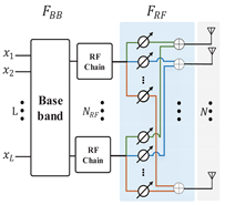
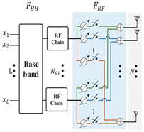
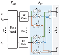
In this section, the multi-user hybrid millimeter wave security communication system is introduced, which is shown in Figure 1. There is a base station Alice with multiple target users , , ..., and an eavesdropper Eve. The antenna subset is driven to transmit signal to ensure that the target user receives the modulated signal correctly, while the eavesdropper receives the noise signal at the same time. The base station is equipped with RF chain and N transmit antennas, which can service L target users and an eavesdropper. The system adopts the uniform linear array with the element space of one-half of the wavelength, which is also suitable for other antenna structures, such as uniform planar array or uniform spherical array.
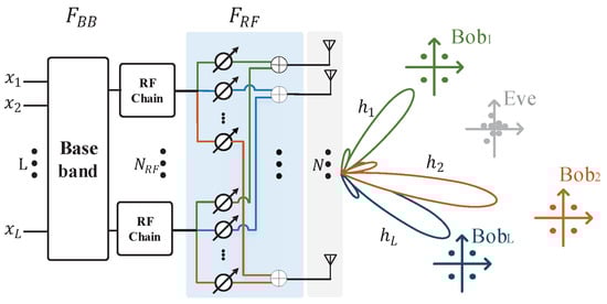
Figure 1.
Multi-user millimeter wave security communication system.
The received signal of L users is expressed as:
where is a channel matrix with , which is the channel vector between target user ℓ and transmitter. Besides, and are the analog precoding vector and digital precoding vector, and , where is the transmission power, and:
where , , is the phase of M-PSK signal, is the amplitude of signal, and .
Without loss of generality, we assume that the channel state information of the target user is perfectly known and the channel information of the eavesdropper is not known. In addition, the target user and the eavesdropper are not in the same direction. We only consider the line of sight (LOS) communication, due to the large channel attenuation of the millimeter wave [22,28]. In order to simplify the mathematical model, we consider the two-dimensional x-y plane model, which only recognizes the azimuth angle and does not consider the influence of the elevation angle. The channel between transmitter and receiver at angle is:
where is the wavelength and d is the distance between the antennas. The L channels at angle compose the channel matrix .
The hybrid beamforming scheme is used in the base station to generate multi-beams according to the direction angle of the target users. The base station first uses a secure analog beamforming scheme to generate analog beams in multiple desired directions, then uses minimum mean square error (MMSE) to design the digital beamforming matrix to eliminate inter-beam interference.
As for the analog security beamforming scheme, the choice of antenna weight affects the performance of secure communication. The conventional, switched, reverse and programmable weighted phased-array transmission scheme is considered in [26] with different antenna weights, which is shown in Table 3. The analog beamforming vector is denoted as the ℓ-th column of , which is shown as follow:,
where is the weight of N antennas, , and ⊙ represents the dot product. We assume that in the antenna weight selection, antennas are set weight k, and else 1, then .
Table 3.
The comparison of traditional beamforming scheme and security beamforming scheme.
The received signal can be expressed as:
where is the scaling factor,
where . Different weight vectors are generated to support different antenna subset transmission techniques by choosing different values of k [26].
In the traditional analog beamforming scheme, all the elements of antenna array have the same weight, that is, , at any discrete-time. The scaling factor can be written as:
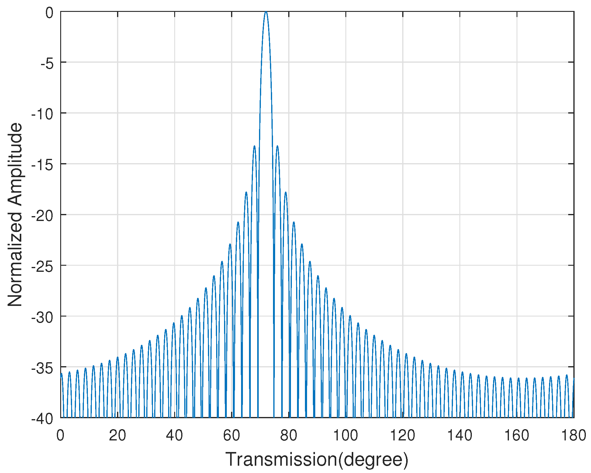
The constellation diagram of the target user is exactly the same as any other angle users, only the power is different. In addition, Equation (7) shows that its radiation pattern is a Sinc wave, which is shown in Figure 2. If the eavesdropper uses a large-aperture antenna or ultra-low sensitivity receiving technology, it is possible for the eavesdropper to recover the target user’s signal. Therefore, the traditional beamforming scheme has poor security communication performance.
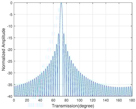
Figure 2.
The radiation pattern of the traditional analog beamforming scheme.
In the optimal weight antenna subset beamforming scheme, it controls the weight of the transmitted signal through a programmable amplifier, and chooses weight 1 with probability p, weight k with probability , so the antenna weight b obeys the Bernoulli distribution:
According to [26], when N is large enough, the scaling factor obeys Gaussian distribution:
The optimal weight antenna subset beamforming scheme maximizes the artificial noise in the direction of an eavesdropper to optimize the weight of each antenna transmission. According to [26], when , the antenna subset achieves an optimal secure performance.
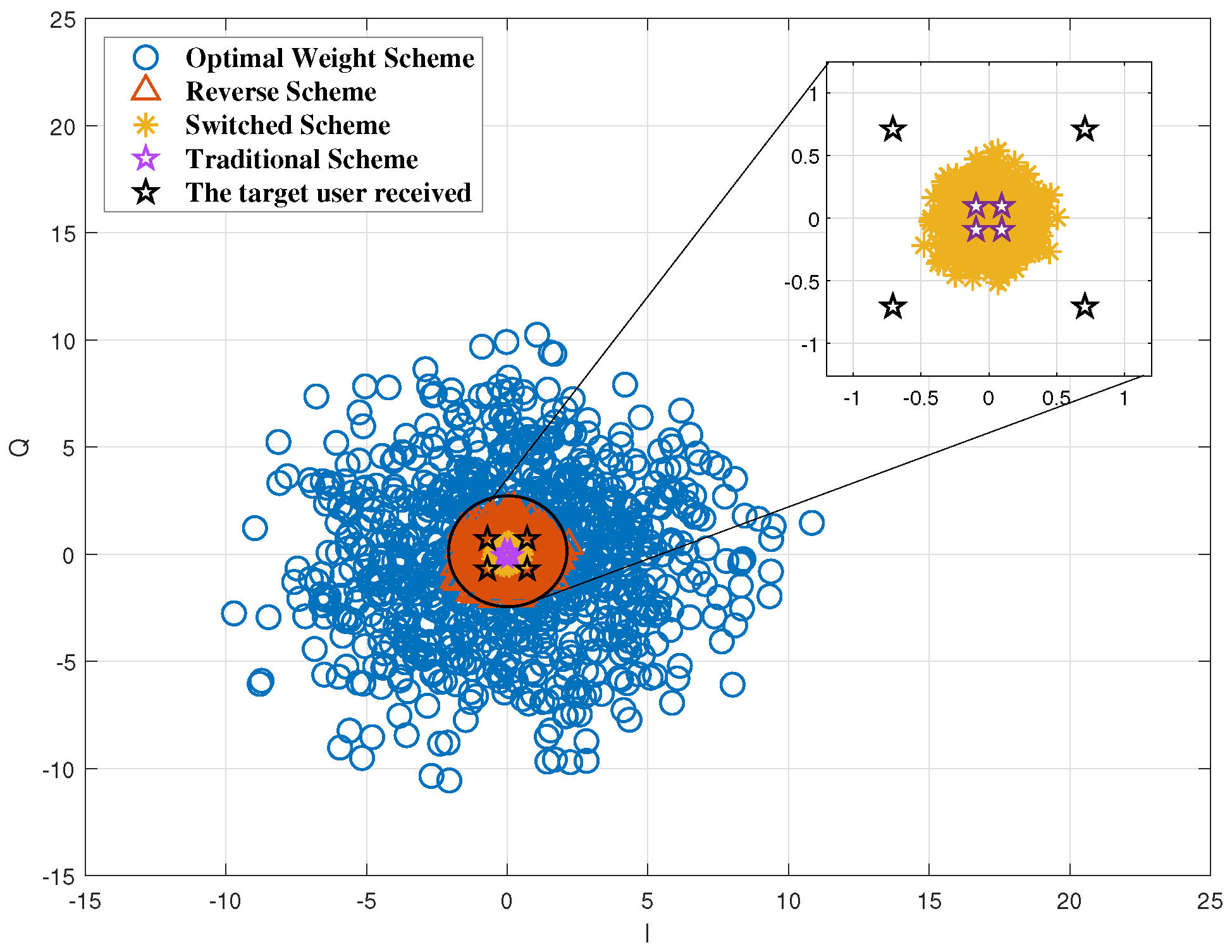
The constellation diagram of a different phased-array transmission scheme in the direction of the eavesdropper is shown as Figure 3. It can be seen from the figure that only the traditional beamforming scheme has the same constellation diagram between the target user and the eavesdropper, and the other schemes’ constellation diagrams of the eavesdropper are all artificial noise because of the selection of a subset of antennas randomly. The optimal weighted antenna subset beamforming scheme has the highest degree of dispersion and the best physical layer security performance, which is adopted to implement analog beamforming in this paper.

Figure 3.
The constellation diagram in the direction of the eavesdropper.
3. CE-Based Analog Precoding Scheme
The above security communication beamforming schemes select appropriate antenna combinations to create artificial noise at the eavesdropper’s direction, but the sidelobe energy of these directions is too high. In order to reduce the signal energy received by the eavesdropper, we use the cross-entropy iterative algorithm to select antenna combinations with low sidelobe energy, so as to ensure that the eavesdropper receives lower signal energy to further enhance the secure performance.
Multi-user hybrid beamforming scheme first uses analog beamforming to generate multiple beams, and then uses MMSE methods to eliminate inter-beam interference. We first consider the analog beamforming. We set as antenna combination, and use a cross-entropy iterative algorithm to choose optimal antenna combination :
where Fitness is the optimized objective function, is the threshold and is the set of all antenna combinations. The probability density distribution function of the antenna combination can be defined as:
where N is the number of transmitting antennas, is the probability that the antenna i is selected, is the indicator function. For a given probability distribution p, the possibility of is:
and the indicator function is:
In order to obtain the optimal probability density distribution function, we set as another probability density distribution function about b, then can be written as:
According to [29], the optimal probability density distribution function is:
The purpose of the cross-entropy iterative algorithm is to minimize the KL (Kullback–Leibler) divergence between and the optimal probability density distribution function . The KL divergence can be written as:
Since is not related to the p, minimizing KL divergence is equivalent to solving the following maximization problem:
The maximization problem can be reduced to:
This function is a convex function, and its partial derivative can be 0 to find the optimal solution:
We set formula (20) equal to 0, the probability of antenna combination iteration can be obtained as:
According to the iterative rule in formula (21), the antenna combination selection strategy can be continuously updated until it converges to the optimal solution. In each iteration process, new samples are generated according to the probability distribution of the previous iteration. These samples have a greater probability of meeting the judgment conditions of the objective function, and then the probability of the next iteration is calculated based on the samples generated this time. Until the stopping strategy is met, the cross-entropy algorithm terminates iteration.
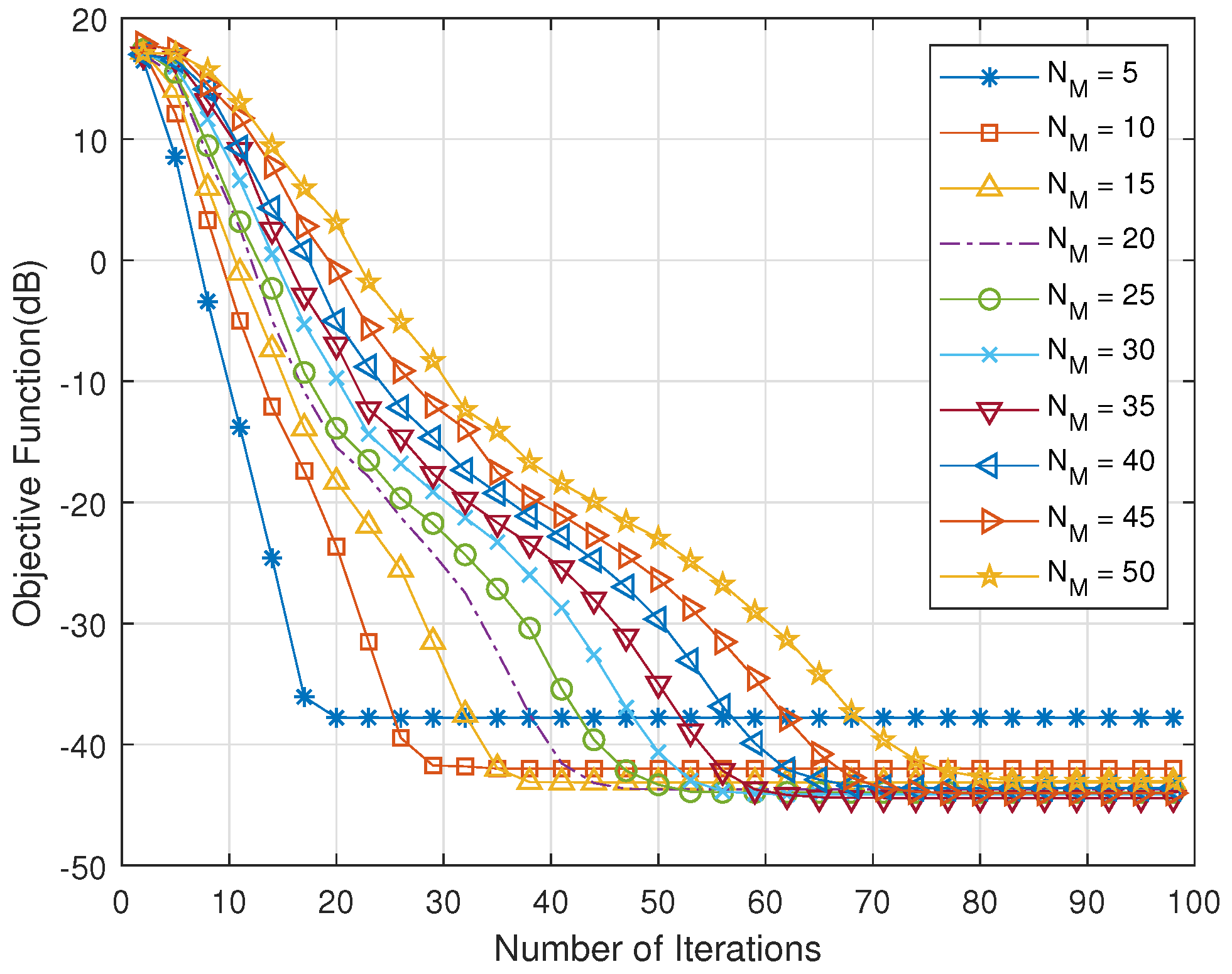
The following is a simulation of the cross-entropy iterative algorithm. The relationship between the number of iterations and the objective function is simulated firstly. Figure 4 shows that, when the number of candidate signals is small, the objective function can converge quickly, but it may converge to the local maximum. In addition, the number of iterations required needs to increase to converge to the optimal value with the number of candidate signals increasing.
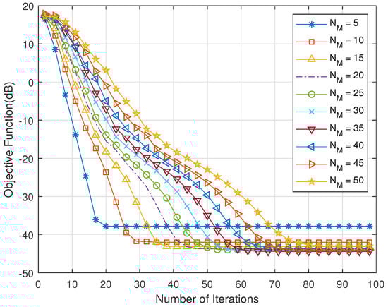
Figure 4.
The relationship between the number of iterations and the objective function.
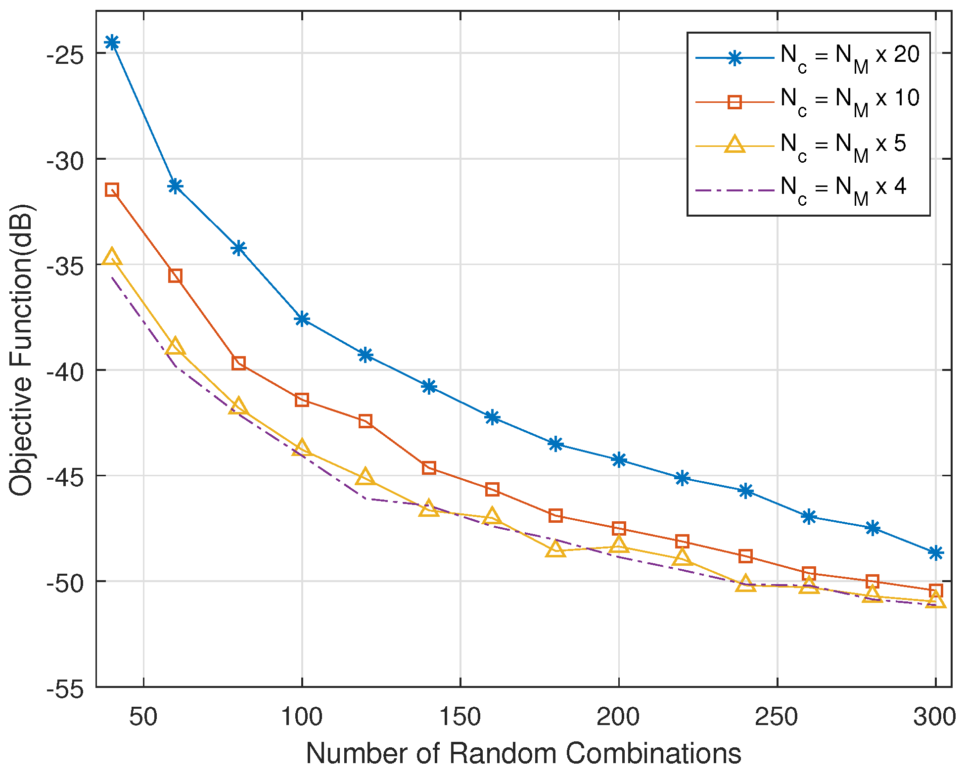
Figure 5 shows the relationship between the number of random combination and objective functions. As the number of random combinations in each iteration increases, the range of each traversal is larger, and it is easier to converge to the optimal value. The optimal value tends to stabilize with the number of random combinations increasing to 200. When the number of candidate combinations is 1/5 of the number of random combinations, it converges to the optimal value.
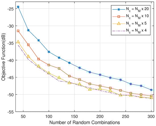
Figure 5.
The relationship between random combination number and objective function.
It can be seen that, as the number of iterations and combinations increase, the objective function can converge to the optimal value. In [30], the authors have proved that when selecting a sufficiently small value of , the limiting probability of generating an optimal solution can be made arbitrarily close to 1. In addition, a smaller value of can reduce the empirical rate of convergence. There is a balance between an optimal solution with high probability and a fast rate of convergence. In order to reduce the computational complexity and increase the convergence rate, we set the smoothing parameter to 1 in this paper.
According to whether the transmitter knows the channel information of the eavesdropper, we have two optimization goals: one is to optimize the sidelobes of a single direction,
the other is to optimize the sidelobes of all non-target directions,
Then, the antenna subset is
where is the set of all non-target users, is the set of all antenna combinations, is the direction angle of the eavesdropper, and is the threshold value, which is used to control the energy of the antenna combination sidelobe.
In order to reduce the energy of the transmitter pattern sidelobe, we propose an analog beamforming scheme based on cross-entropy iterative algorithm which is shown in Algorithm 1. The algorithm first inputs the number of random antenna combinations , the number of candidate signals , the total number of iterations , and smoothing parameter and initializes the probability of each antenna weight to 1 with to . Then, the objective function value of each combination is calculated and sorted. Next, we take the first sorted antenna combinations with and calculate the iterative probability of the antenna combination. We use the probability to perform the next iteration until the number of iterations is completed, at last the algorithm outputs the antenna combination .
| Algorithm 1 Analog Beamforming Scheme Based on Cross-Entropy Iterative Algorithm. |
Input: Number of Random Combinations , Number of Candidate Combinations , Total Number of Iterations , Smoothing Parameter Initialization: Probability of each antenna weight to 1, , Number of iterations
Output: Antenna Combination . |
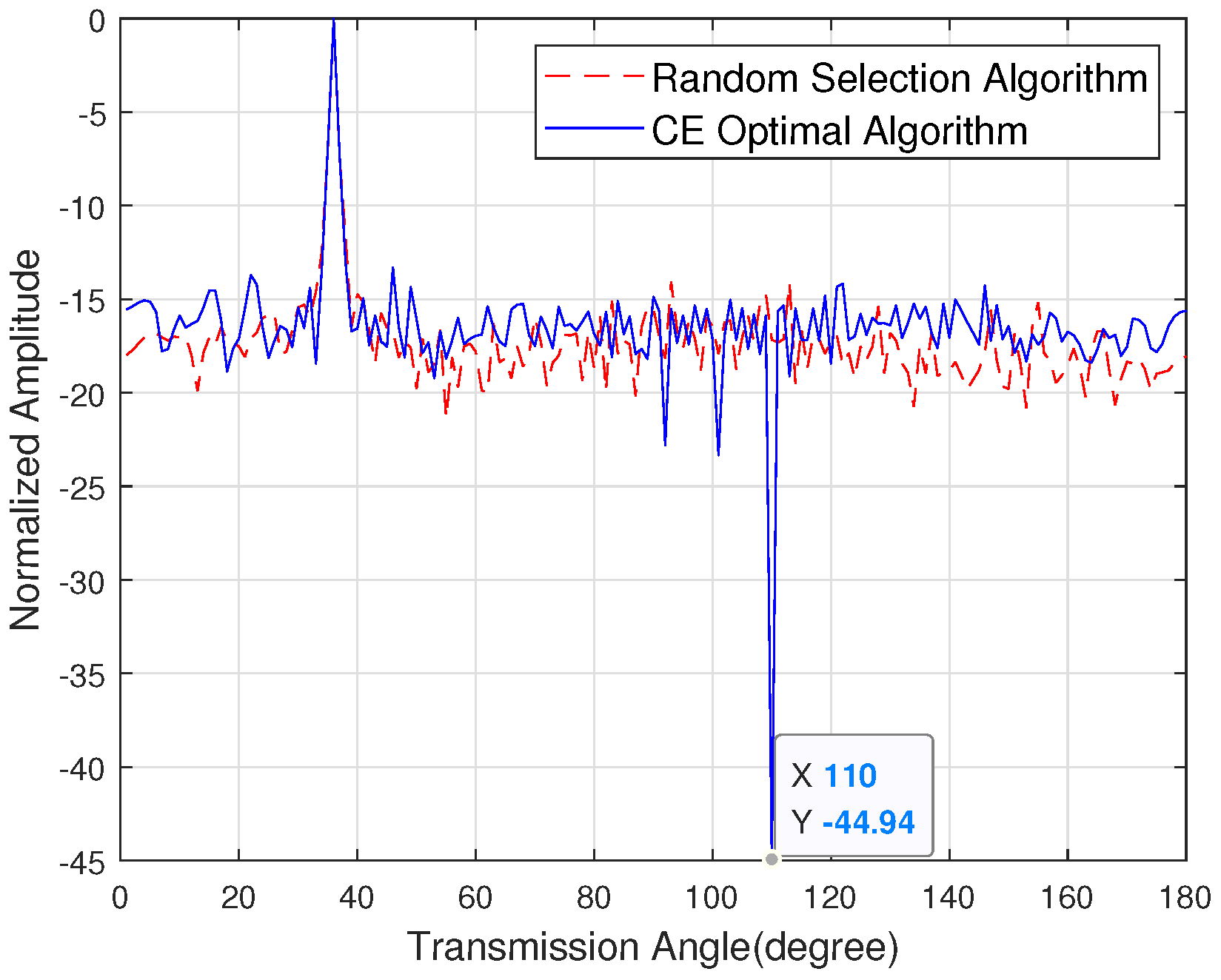
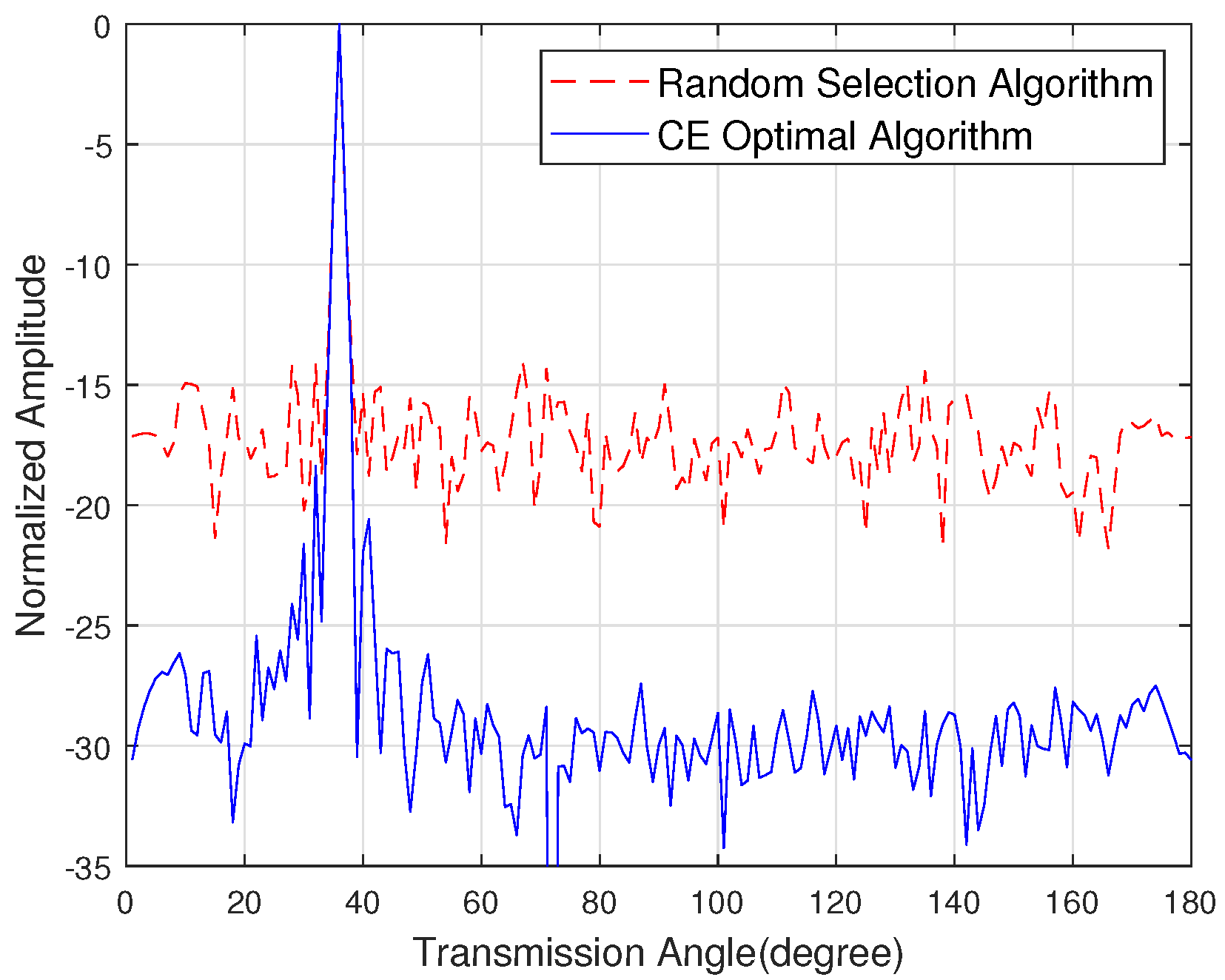
Figure 6 shows the sidelobe energy of the emission pattern when the eavesdropper angle is 80 degrees, the target user angle is 36 degrees and the number of antennas is 128. The random selection algorithm is introduced in [31]. The simulation shows that the sidelobe energy suppression in the eavesdropper direction is 44.94 dB. Figure 7 shows the sidelobe energy of the emission pattern when the direction of the eavesdropper is unknown, the target user angle is 40 degrees and the number of antennas is 128. The simulation shows that the sidelobe energy of the CE optimal algorithm is 10 dB lower than the random selection algorithm.
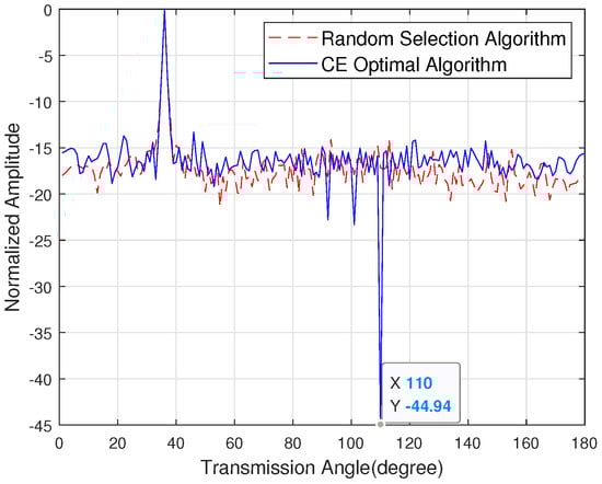
Figure 6.
The sidelobe energy of the emission pattern with the known channel state information of the eavesdropper.

Figure 7.
The sidelobe energy of the emission pattern with the unknown channel state information of the eavesdropper.
4. CE-Based Multi-User Hybrid Precoding Scheme
The previous section has introduced the design of analog beamforming algorithm, this section mainly introduces the design of the multi-user hybrid beamforming algorithm. The received signal of the multi-user hybrid beamforming in secure communication system is:
where represents the dot product of and each column of .
We set as the equivalent channel, formula (25) can be written as:
We use MMSE methods to design the digital beamforming matrix , thereby eliminating interference between multiple users.
Based on the above formulas, We propose a multi-user hybrid procoding scheme based on cross-entropy iteration which is shown in Algorithm 2. The input of this algorithm is the number of random combinations , the number of candidate signals , the number of iterations , the number of users L, and smoothing parameter . Then we initialize the probability of each antenna weight to 1 with to . First, we generate antenna combination vectors. According to the multi-user channel, we calculate the simulated precoding vector of antenna combinations , and the equivalent channel based on the simulated precoding vector . Then, the MMSE algorithm is adopted to calculate the digital precoding vector to eliminate the interference between multiple user beams, so as to ensure the normal transmission of data between multiple users. Next, we calculate the fitness of the pattern sidelobes generated by the antenna combinations and sort to obtain . According to the sorted sequence, the first antenna combination with is used to calculate the probability for the next iteration. Until the iteration ends, the antenna combination with low sidelobes of the pattern is output. In addition, Algorithm 2 can also be applied to other channel models because it only relates to the channel matrix . However, due to the existence of multipath in other channel model, the sidelobe energy will increase, making the performance of the proposed algorithm worse. Besides, how to set threshold for the fitness evaluation is an open question. We know that, when the threshold is smaller, the sidelobes of the pattern are lower but the number of antenna combinations that meet the requirements is less and the threshold is larger, the sidelobes of the pattern are higher, but the number of antenna combinations that meets the requirements is greater.
| Algorithm 2 Hybrid Beamforming Scheme Based on Cross-Entropy Iterative Algorithm. |
Input: Number of Random Combinations , Number of candidate Combinations , Total Number of iterations , Number of Users L, Smoothing Parameter Initialization: Probability of each antenna weight to 1, , Number of iterations
Output: Antenna Combination . |
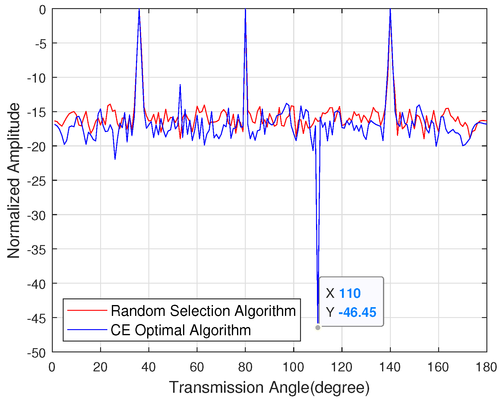
Figure 8 shows the sidelobe energy of the emission pattern under the known eavesdropper angle. A multi-user hybrid beamforming algorithm based on cross-entropy is used to iterate the random antenna combination, and the sidelobe energy is selected to be lower. In the direction of the target user, the normalized amplitude of the mainlobe energy of the target user is all 0 dB, and the sidelobe suppression reaches 46.45 dB in the direction of the eavesdropper.
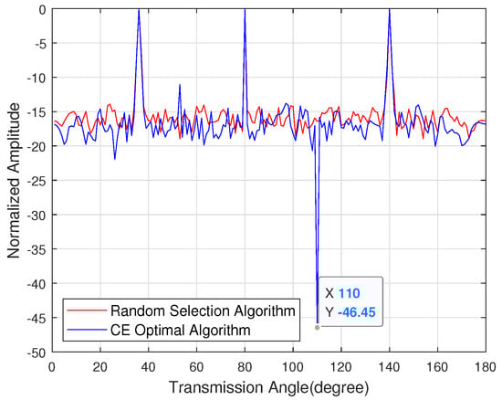
Figure 8.
The sidelobe energy of the emission pattern with the known channel state information of the eavesdropper.
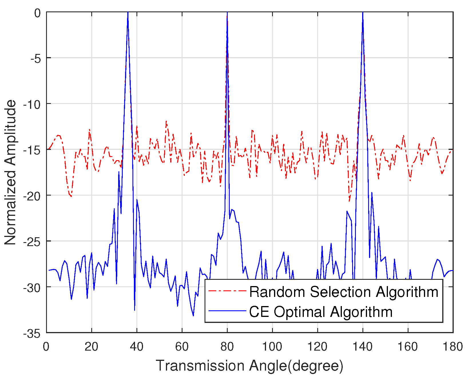
Figure 9 shows the sidelobe energy of the emission pattern under the unknown eavesdropper angle. By optimizing the sidelobe energy in the direction of non-target users, the antenna combination with lower sidelobe energy is obtained. The sidelobe energy with the CE optimal algorithm is 10 dB lower than the random selection algorithm, which allows multiple target users to communicate normally while eavesdroppers receive low energy noise constellations, thereby further improving secure communication.
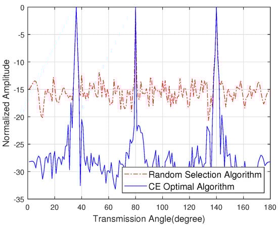
Figure 9.
The sidelobe energy of the emission pattern with the unknown channel state information of the eavesdropper.
5. Simulation Results
According to the CE-based multi-user hybrid beamforming algorithm, the physical layer security performance of the millimeter-wave communications system is simulated in this section. The influence of using the CE optimal algorithm and the random selection algorithm on the sidelobe energy and symbol error rate of the system is analyzed. The simulation parameters are shown in Table 4.
Table 4.
Simulation parameter table.
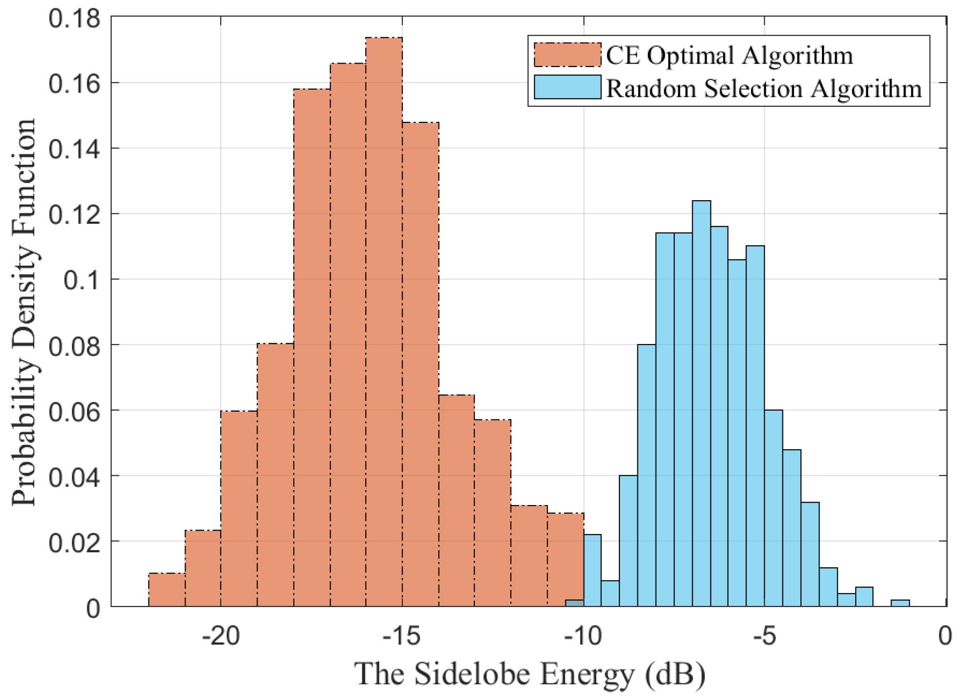
Figure 10 shows the probability density distribution function of the sidelobe energy. This figure first calculates the emission pattern based on the CE optimal algorithm and the random selection algorithm and normalizes the sidelobe energy by subtracting the mainlobe energy. Then, the normalized maximum sidelobe is obtained. The probability density distribution function of the maximum sidelobe energy is acquired by Monte Carlo simulation. It can be shown that the sidelobe energy obtained by the random selection algorithm is mainly distributed around −7 dB, while the sidelobe energy of the CE optimal algorithm is −17 dB, and both have a Gaussian-like distribution.

Figure 10.
The probability density distribution function of the sidelobe energy.
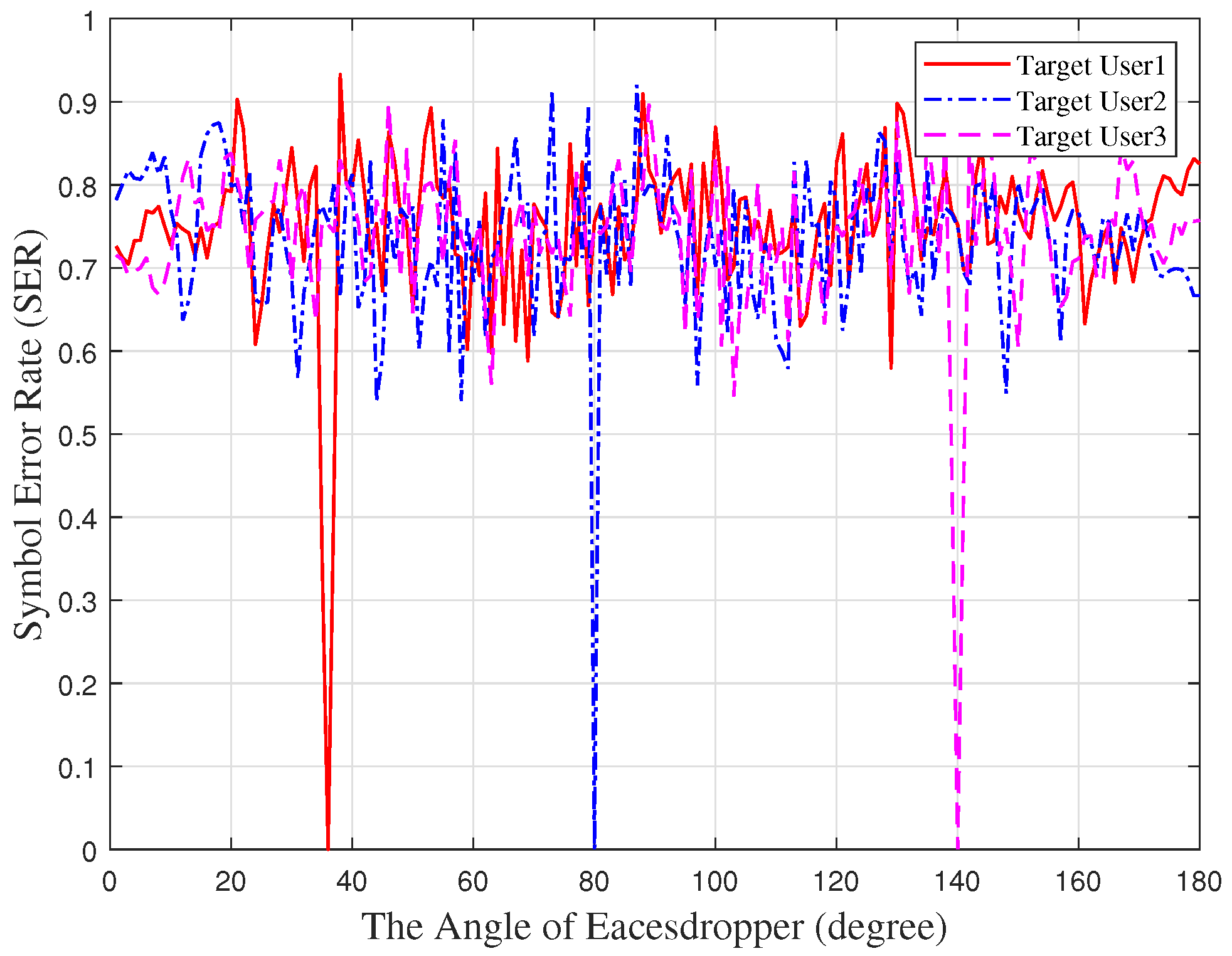
Figure 11 shows the relationship between the angle of the eavesdropper and the symbol error rate. The eavesdropper demodulates the symbols of target user1, target user2, target user3 from different angles and calculates the symbol error rate. It can be seen that, when the eavesdropper and the target user are located in the same direction, the symbol error rate tends to zeros. The symbol can be perfectly demodulated when the eavesdropper has a large-scale antenna or an ultra-low sensitivity receiver. Furthermore, the symbol error rate is about 0.75 when the eavesdropper is at other angles. Due to the constellation diagram being noise, it is difficult for the eavesdropper to demodulate the symbols.
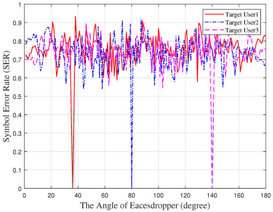
Figure 11.
The symbol error rate against the angle of the eavesdropper.
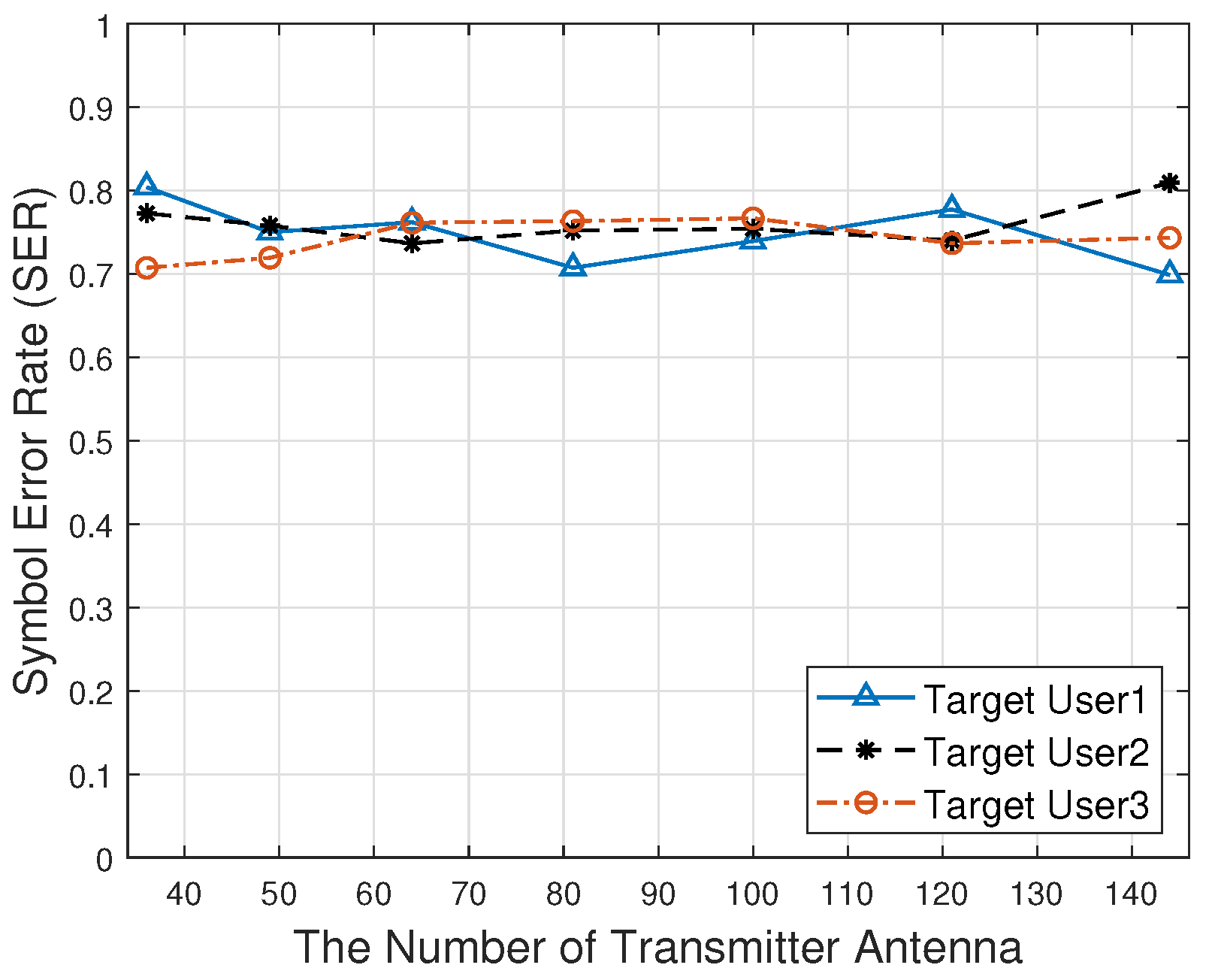
Figure 12 shows the relationship between the number of transmitter antennas and the symbol error rate. As the number of transmitter antennas increases, the symbol error rate is always approximately 0.75. The eavesdropper cannot correctly obtain the information transmitted by the target users.
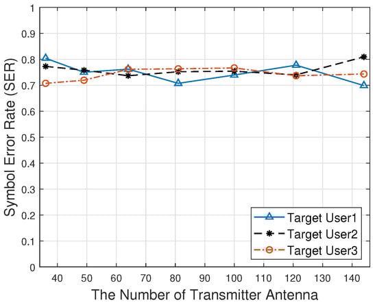
Figure 12.
The symbol error rate against the number of the transmitter antenna.
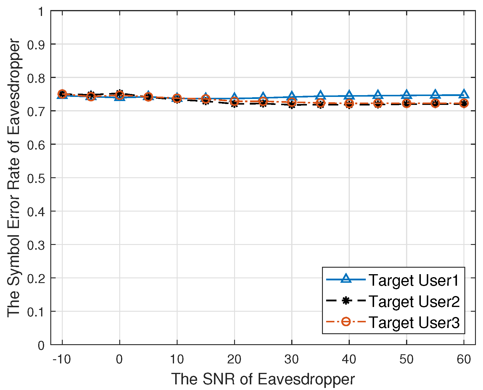
Figure 13 shows the relationship between the SNR of the eavesdropper and the symbol error rate. When the direction of the eavesdropper is not the same as the target user, as the SNR increases, the symbol error rate is always approximate 0.75. The signal cannot be demodulated correctly, which has a good security communication performance.
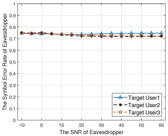
Figure 13.
The symbol error rate against the SNR of the eavesdropper.
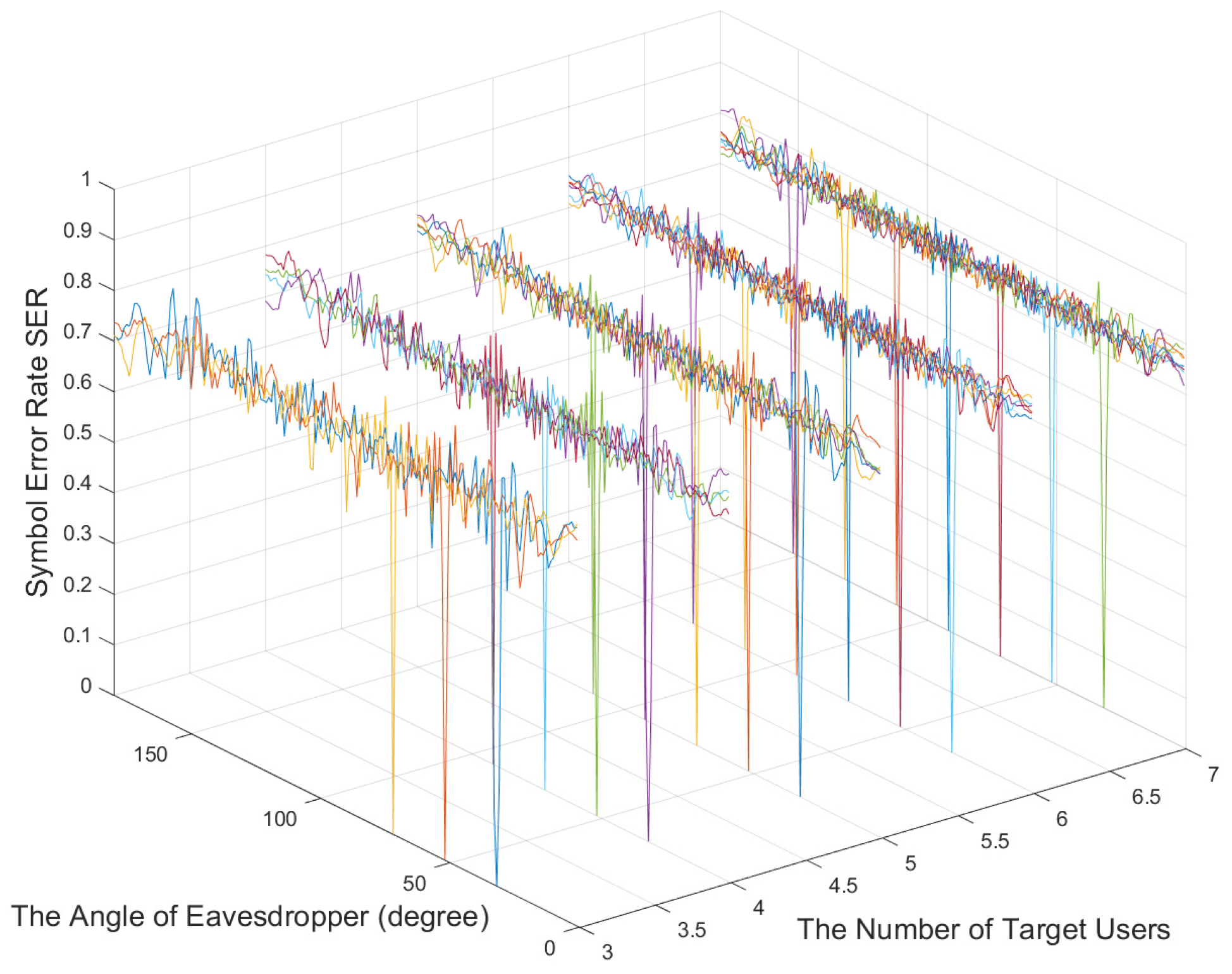
Figure 14 shows the relationship between the number of target users and the symbol error rate. As the number of target users increases, the symbol error rate does not deteriorate and is maintained at about 0.75 when the number of target users is less than that of the RF chains. Therefore, the CE optimal algorithm can achieve a better physical layer security communication performance.
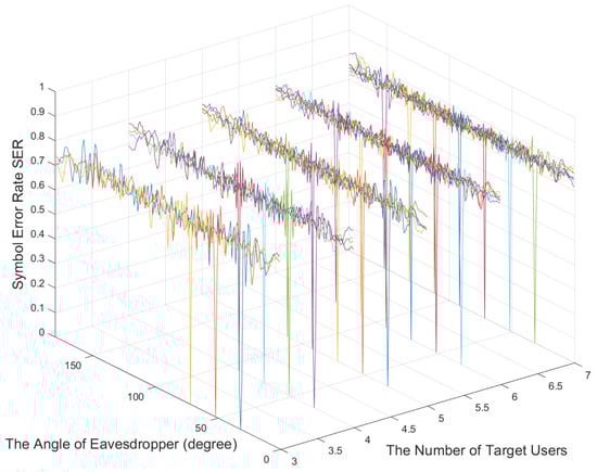
Figure 14.
The relationship between the number of target users and the symbol error rate.
6. Conclusions
In this paper, we propose a CE optimal based hybrid beamforming design algorithm for multi-user physical layer security modulation techniques. We first adopt the hybrid beamforming method and randomly select the antenna to transmit the signal at the symbol rate. In addition, in order to solve the problem of the high sidelobe energy of randomly selected antennas, this paper proposes a cross-entropy iteration method to choose the optimal antenna combination to transmit signals, thereby reducing the energy of eavesdropper-received signals and further improving the system’s security performance. The simulation shows that the proposed method has about 10 dB lower sidelobe energy than does the random selection method. Besides, while multiple target users are communicating normally, the eavesdropper’s symbol error rate of QPSK is always 0.75, which has a good physical layer security communication performance. In future research, a hybrid beamforming design scheme for physical layer secured mmWave communications in other channel models will be studied to realize the multi-user physical layer security.
Author Contributions
Formal analysis, J.L., N.Y., S.M. and X.B.; Funding acquisition, J.A.; Writing—original draft, J.L.; Writing—review and editing, J.L. and N.Y. All authors have read and agreed to the published version of the manuscript.
Funding
This research was funded by National Scientific Foundation of China under grants 61620106001, 62001030, and 62101048.
Conflicts of Interest
The authors declare no conflict of interest.
References
- Psomas, C.; Krikidis, I. Energy Beamforming in Wireless Powered mmWave Sensor Networks. IEEE J. Sel. Areas Commun. 2019, 37, 424–438. [Google Scholar] [CrossRef]
- Chang, B.; Zhao, G.; Zhang, L.; Imran, M.A.; Chen, Z.; Li, L. Dynamic Communication QoS Design for Real-Time Wireless Control Systems. IEEE Sens. J. 2020, 20, 3005–3015. [Google Scholar] [CrossRef]
- Guo, F.; Yu, F.R.; Zhang, H.; Li, X.; Ji, H.; Leung, V.C.M. Enabling Massive IoT Toward 6G: A Comprehensive Survey. IEEE Internet Things J. 2021, 8, 11891–11915. [Google Scholar] [CrossRef]
- Lin, W.; Matsumoto, T. Performance Analysis of Distortion-Acceptable Cooperative Communications in Wireless Sensor Networks for Internet of Things. IEEE Sens. J. 2019, 19, 1979–1989. [Google Scholar] [CrossRef] [Green Version]
- Busari, S.A.; Huq, K.M.S.; Mumtaz, S.; Dai, L.; Rodriguez, J. Millimeter-Wave Massive MIMO Communication for Future Wireless Systems: A Survey. IEEE Commun. Surv. Tutor. 2018, 20, 836–869. [Google Scholar] [CrossRef]
- Gao, X.; Feng, S.; Niyato, D.; Wang, P.; Yang, K.; Liang, Y.C. Dynamic Access Point and Service Selection in Backscatter-Assisted RF-Powered Cognitive Networks. IEEE Internet Things J. 2019, 6, 8270–8283. [Google Scholar] [CrossRef]
- Zhang, J.; Huang, Y.; Wang, J.; Schober, R.; Yang, L. Power-Efficient Beam Designs for Millimeter Wave Communication Systems. IEEE Trans. Wireless Commun. 2020, 19, 1265–1279. [Google Scholar] [CrossRef]
- Ju, Y.; Wang, H.M.; Zheng, T.X.; Yin, Q.; Lee, M.H. Safeguarding Millimeter Wave Communications Against Randomly Located Eavesdroppers. IEEE Trans. Wireless Commun. 2018, 17, 2675–2689. [Google Scholar] [CrossRef] [Green Version]
- Liu, R.; Yu, G.; Yuan, J.; Li, G.Y. Resource Management for Millimeter-Wave Ultra-Reliable and Low-Latency Communications. IEEE Trans. Commun. 2021, 69, 1094–1108. [Google Scholar] [CrossRef]
- An, J.; Zhang, Y.; Gao, X.; Yang, K. Energy-Efficient Base Station Association and Beamforming for Multi-Cell Multiuser Systems. IEEE Trans. Wirel. Commun. 2020, 19, 2841–2854. [Google Scholar] [CrossRef]
- Furqan, H.M.; Solaija, M.S.J.; Türkmen, H.; Arslan, H. Wireless Communication, Sensing, and REM: A Security Perspective. IEEE Open J. Commun. Soc. 2021, 2, 287–321. [Google Scholar] [CrossRef]
- Wu, Y.; Khisti, A.; Xiao, C.; Caire, G.; Wong, K.K.; Gao, X. A Survey of Physical Layer Security Techniques for 5G Wireless Networks and Challenges Ahead. IEEE J. Sel. Areas Commun. 2018, 36, 679–695. [Google Scholar] [CrossRef] [Green Version]
- Wang, W.Q.; Zheng, Z. Hybrid MIMO and Phased-Array Directional Modulation for Physical Layer Security in mmWave Wireless Communications. IEEE J. Sel. Areas Commun. 2018, 36, 1383–1396. [Google Scholar] [CrossRef]
- Qing, L.; Guangyao, H.; Xiaomei, F. Physical Layer Security in Multi-Hop AF Relay Network Based on Compressed Sensing. IEEE Commun. Lett. 2018, 22, 1882–1885. [Google Scholar] [CrossRef]
- Jameel, F.; Wyne, S.; Kaddoum, G.; Duong, T.Q. A Comprehensive Survey on Cooperative Relaying and Jamming Strategies for Physical Layer Security. IEEE Commun. Surv. Tutor. 2019, 21, 2734–2771. [Google Scholar] [CrossRef] [Green Version]
- Zhang, W.; Chen, J.; Kuo, Y.; Zhou, Y. Transmit Beamforming for Layered Physical Layer Security. IEEE Trans. Veh. Technol. 2019, 68, 9747–9760. [Google Scholar] [CrossRef]
- Hu, D.; Mu, P.; Zhang, W.; Wang, W. Minimization of Secrecy Outage Probability With Artificial-Noise-Aided Beamforming for MISO Wiretap Channels. IEEE Commun. Lett. 2020, 24, 401–404. [Google Scholar] [CrossRef]
- Song, J.; Lee, B.; Park, J.; Lee, M.S.; Lee, J.H. Beamformer Design for Physical Layer Security in Dual-Polarized Millimeter Wave Channels. IEEE Trans. Veh. Technol. 2020, 69, 12306–12311. [Google Scholar] [CrossRef]
- Nandan, N.; Majhi, S.; Wu, H.C. Beamforming and Power Optimization for Physical Layer Security of MIMO-NOMA Based CRN Over Imperfect CSI. IEEE Trans. Veh. Technol. 2021, 70, 5990–6001. [Google Scholar] [CrossRef]
- Lv, T.; Gao, H.; Yang, S. Secrecy Transmit Beamforming for Heterogeneous Networks. IEEE J. Sel. Areas Commun. 2015, 33, 1154–1170. [Google Scholar] [CrossRef] [Green Version]
- Gu, Y.; Wu, Z.; Yin, Z.; Zhang, X. The Secrecy Capacity Optimization Artificial Noise: A New Type of Artificial Noise for Secure Communication in MIMO System. IEEE Access 2019, 7, 58353–58360. [Google Scholar] [CrossRef]
- Xie, T.; Zhu, J.; Li, Y. Artificial-Noise-Aided Zero-Forcing Synthesis Approach for Secure Multi-Beam Directional Modulation. IEEE Commun. Lett. 2018, 22, 276–279. [Google Scholar] [CrossRef]
- Yu, X.; Hu, Y.; Pan, Q.; Dang, X.; Li, N.; Shan, M.H. Secrecy Performance Analysis of Artificial-Noise-Aided Spatial Modulation in the Presence of Imperfect CSI. IEEE Access 2018, 6, 41060–41067. [Google Scholar] [CrossRef]
- Valliappan, N.; Lozano, A.; Heath, R.W. Antenna Subset Modulation for Secure Millimeter-Wave Wireless Communication. IEEE Trans. Commun. 2013, 61, 3231–3245. [Google Scholar] [CrossRef] [Green Version]
- Alotaibi, N.N.; Hamdi, K.A. Switched Phased-Array Transmission Architecture for Secure Millimeter-Wave Wireless Communication. IEEE Trans. Commun. 2016, 64, 1303–1312. [Google Scholar] [CrossRef]
- Hong, Y.; Jing, X.; Gao, H. Programmable Weight Phased-Array Transmission for Secure Millimeter-Wave Wireless Communications. IEEE J. Sel. Top. Signal Process. 2018, 12, 399–413. [Google Scholar] [CrossRef]
- Zhang, X.; Xia, X.G.; He, Z.; Zhang, X. Phased-Array Transmission for Secure mmWave Wireless Communication via Polygon Construction. IEEE Trans. Signal Process. 2020, 68, 327–342. [Google Scholar] [CrossRef]
- Hafez, M.; Yusuf, M.; Khattab, T.; Elfouly, T.; Arslan, H. Secure Spatial Multiple Access Using Directional Modulation. IEEE Trans. Wirel. Commun. 2018, 17, 563–573. [Google Scholar] [CrossRef]
- Rubinstein, R.Y.; Kroese, D.P. The Cross-Entropy Method: A Unified Approach to Combinatorial Optimization, Monte-Carlo Simulation and Machine Learning; Springer: Berlin, Germany, 2013. [Google Scholar]
- Costa, A.; Jones, O.D.; Kroese, D. Convergence properties of the cross-entropy method for discrete optimization. Oper. Res. Lett. 2007, 35, 573–580. [Google Scholar] [CrossRef] [Green Version]
- Hafez, M.; Arslan, H. On directional modulation: An analysis of transmission scheme with multiple directions. In Proceedings of the 2015 IEEE International Conference on Communication Workshop (ICCW), London, UK, 8–12 June 2015; pp. 459–463. [Google Scholar] [CrossRef]

Publisher’s Note: MDPI stays neutral with regard to jurisdictional claims in published maps and institutional affiliations. |
© 2021 by the authors. Licensee MDPI, Basel, Switzerland. This article is an open access article distributed under the terms and conditions of the Creative Commons Attribution (CC BY) license (https://creativecommons.org/licenses/by/4.0/).