Article

Using a Two-Stage Method to Reject False Loop Closures and Improve the Accuracy of Collaborative SLAM Systems

School of Instrument Science and Engineering, Southeast University, Nanjing 210096, China
*
Author to whom correspondence should be addressed.
Electronics 2021, 10(21), 2638; https://doi.org/10.3390/electronics10212638
Submission received: 8 October 2021 / Revised: 22 October 2021 / Accepted: 23 October 2021 / Published: 28 October 2021
(This article belongs to the Section Systems & Control Engineering)

Abstract

:
Loop-closure detection is an essential means to reduce accumulated errors of simultaneous localization and mapping (SLAM) systems. However, even false positive loop closures could seriously interfere and even corrupt the back-end optimization process. For a collaborative SLAM system that generally uses both intra-robot and inter-robot loop closures to optimize the pose graph, it is a tough job to reject those false positive loop closures without a reliable a priori knowledge of the relative pose transformation between robots. Aiming at this solving problem, this paper proposes a two-stage false positive loop-closure rejection method based on three types of consistency checks. Firstly, a multi-robot pose-graph optimization model is given which transforms the multi-robot pose optimization problem into a maximum likelihood estimation model. Then, the principle of the false positive loop-closure rejection method based on χ 2 test is proposed, in which clustering is used to reject those intra-robot false loop-closures in the first step, and a largest mutually consistent loop-based χ 2 test is constructed to reject inter-robot false loop closures in the second step. Finally, an open dataset and synthetic data are used to evaluate the performance of the algorithms. The experimental results demonstrate that our method improves the accuracy and robustness of the back-end pose-graph optimization with a strong ability to reject false positive loop closures, and it is not sensitive to the initial pose at the same time. In the Computer Science and Artificial Intelligence Lab (CSAIL) dataset, the absolute position error is reduced by 55.37% compared to the dynamic scaling covariance method, and the absolute rotation error is reduced by 77.27%; in the city10,000 synthetic dataset, the absolute position error is reduced by 89.37% compared to the pairwise consistency maximization (PCM) and the absolute rotation error is reduced by 97.9%.

1. Introduction

Compared to single-robot SLAM systems, a collaborative SLAM system can more efficiently explore unknown environments with more robust and higher accurate mapping and positioning performance [1], in which the individual robot not only estimates its trajectory and surrounding maps, but also can use the shared information to implement collaborative localization, mapping, and collision avoidance. Therefore, the collaborative SLAM system has gotten more and more applications in fields such as indoor mapping, pollution detection, and disaster rescue [2,3].
Loop-closure detection, through recognizing the previously visited place is widely used to mitigate the cumulative error in the SLAM system. Many studies have been conducted on loop-closure detection, and Bag of Words [4]—as the representative method of appearance-based loop-closure detection—has been verified in many popular SLAM systems [5,6]. Nevertheless, due to the existence of perceptual aliasing and perceptual variability, the occurrence of false loop-closure cases is inevitable, which could highly affect the precision and robustness of the SLAM system.
Figure 1 shows a typical experiment to demonstrate the impact of false positive loop closures to the pose graph optimization results, the dataset is courtesy of Michael Kaess and was published along with iSAM2 [7], which includes 2500 vertices connected by 4949 edges. In the following experiment, 50 false positive loop-closure edges were randomly added which only occupy 1% of the total edges in the pose graph, where Figure 1a,c are the original pose graph without any optimization and the pose graph with 50 false positive loop-closure edges randomly added, respectively. Figure 1b,d are the optimization results using Gauss-Newton optimization method iterated 10 times of Figure 1a,b, respectively, and Figure 1b provides almost perfect results while Figure 1d presents totally corrupted results. From the figures, we can see the high importance of false positive loop-closure detection.
More than that, in the collaborative SLAM system, loop closures to be detected include both intra-robot and inter-robot loop closures. A single-robot SLAM system usually evaluates a candidate loop closure based on the local reliable nature of the odometer measurement value and rejects those loop measurement edges with large residual error [8]. In a collaborative SLAM system, generally, the pairwise internal consistency information between the loop measurement value and the local odometer measurement could be used to reject false inter-robot loop closure; however, since there is usually a lack of mutual pose transformation a priori knowledge, it is a big challenge to concurrently run both intra-robot and inter-robot loop-closure rejection.
Aiming at this problem, this paper proposes a two-stage false loop-closure rejection method based on three types of consistency checks, which can be embedded into the collaborative SLAM system to improve the accuracy of the whole system. Firstly, this paper establishes a multi-robot pose graph model which transfers the collaborative SLAM bundle adjustment problem into a maximum likelihood estimation one. Then, the principle of false positive loop-closure rejection method based on the χ 2 test is proposed, in which the clustering method is used to reject intra-robot false loop-closures in the first step, and a largest-mutually-consistence-loop based χ 2 test is constructed to reject those inter-robot false loop closures in the second step. Finally, the open dataset and the synthetic data are used to evaluate the performance of the given algorithm. The experimental results show that our method improves the robustness of the pose-graph optimization process during removing of perceptual aliasing, and it can improve the positioning accuracy and is not sensitive to the initial pose at the same time. In addition, the proposed approach is easy to port to existing popular collaborative SLAM systems.

2. Related Works

In pose graph SLAM, problems are often formulated as a maximum likelihood estimate of the time discretized robot trajectory given odometric and loop closure measurements [9,10] through recognizing the previously visited place. Loop closure technique can mitigate the cumulative error and appearance-based loop-closure detection [4] has been widely used. At the same time, the use of semantic information on place recognition has attracted a lot of interest recently [11], while considering that a false positive loop closure could highly downgrade and even corrupt the back-end optimization process of SLAM systems [12,13,14], it is of great value to effectively identify and reject false loop closures to obtain more accurate positioning results and more robust positioning performance both for single-robot and multi-robot collaborative SLAM systems. The aforementioned objective could be realized through improving the accuracy of place recognition, for example by using deep learning or other novel technologies, but it should be pointed out that mismatches are almost inevitable, especially in large scenarios involving collaborative SLAM systems. Therefore, it is essential to explore the approach to effectively reject false positive loop closure both for single-robot and multi-robot SLAM systems.

2.1. False Loop-Closure Rejection for Single-Robot SLAM Systems

In computer vision, random sample consensus (RANSAC) is a frequently used method to estimate the parameters of a mathematical model from a set of data containing outliers and then identify them. However, the actual verification in the literature shows that it is difficult to model the pose graph with a certain model for either a single-robot or a collaborative SLAM system [8], which means it is difficult to determine whether a detected loop closure within a robot or between different robots is an inlier or outlier. A practical way is to check whether it has consistency with the rest of the measurements, and then determine whether the loop closure is true or false according to the consistency check.
To reduce the impact of false loop closures in a single-robot SLAM system, the two-norm error measurement is usually replaced by a robust kernel function to mitigate the impact of those measurement edges with big errors on the optimization process [15]. Considering that the back-ends of most existing SLAM systems are based on the least square optimization and are not robust against outliers, Sünderhauf [16] proposed a robust back-end formulation using switchable constraints, which made the topology of the underlying factor graph representation subject to optimization instead of keeping fixed by introducing additional variables named switchable constraints to allow the false loop closures that produce large errors to be switched off during optimization. Such a solution increases the robustness of the SLAM system. However, the computation complexity is thereby increased for introducing new constraints. To overcome the preceding problem, Agarwal et al. [17] introduced the dynamic covariance scaling (DCS) method for the effective optimization of constraint networks under the presence of outliers through analyzing the behavior of the error function and deriving an analytical solution for computing the weighting factors, which generalized the switchable constraint method of Sunderhauf [16] only with a substantially lower computational overhead. However, both the aforesaid methods need to manually set the threshold value of the prior covariance matrix of the switching variable to represent the uncertainty, and the setting of this parameter lacks a strict mathematical explanation. As mentioned in Sünderhauf’s article [16], this parameter is either provided by the front end or obtained as an empirical value through a large number of experiments.
Recently, convex relaxation has become a frequently used approach to make the solution not fall into the local optimal value during the optimization process. Carlone [18] used ℓ₁-relaxation to turn the solution of the objective function into a convex optimization problem and used ℓ0-norm to find out true positive loop closures. In addition, semi-positive definite relaxation [19] has also been applied to model the heavy-tailed measurement. However, such methods are also sensitive to system parameters [20]. It should be pointed out that neither the switchable constraints nor the convex relaxation method is suitable for the incremental rejection of false loop closures. As known, when the above method attempts to determine whether a loop closure is a false positive or not, complete pose graph information is required, so they are difficult to be directly applied to those online SLAM systems [21].
Aiming at accelerating the speed of false positive closures rejection, Latif et al. [22] gave a consensus-based approach for robust place recognition in real-time. In that approach, loop-closures were clustered by their time intervals, and the concept of consistency between loop-closures as well as consistency checking method based on the χ 2 distribution was introduced, and which were adopted to remove false positive loop-closure from the online pose graph. However, this method could directly reject the whole cluster since only inter-consistency checks were performed, and potential correct loop-closures inside the rejected cluster were not used to eliminate accumulated errors.

2.2. False Positive Closure Rejection in a Collaborative SLAM System

Compared with the problem of false positive closure rejection of a single robot, it is a relatively more complex problem to reject false positive loop-closures in a collaborative SLAM system, since there is a lack of reliable a priori knowledge of relative pose transformation between different robots [16,18] and there also lack credible speedometer measurements [8]. Neira and his colleagues [23] proposed the joint compatibility branch and bound (JCBB) algorithm which selected loop-closures by seeking to determine the maximum jointly compatible set. However, performing JCBB in a multi-robot system is difficult because it needs to solve the graph for a combinatorial number of measurement combinations to evaluate the likelihood of each measurement given each combination of the other measurements, and with the increase of the number of loop-closures, the consumed time of problem solving increases sharply. Considering the high correlation between those abnormal loop-closures, Lajoie [24] established a discrete-continuous graphical model (DC-GM) explicitly representing the impact of perceptual aliasing, and turned the non-convex combinatorial optimization problem of the DC-GM into a semi-positive definite optimization (SDP) by using convex relaxation technology. Similar to single-robot false positive closure rejection, this method is equally sensitive to the system parameters.
The effectiveness of the pairwise consistent measurement (PCM) method [8], based on the maximum clique, has been widely verified in both real-time collaborative SLAM systems [20,25] and single-robot SLAM systems [26]. It is known that, in order to use PCM in a SLAM system, it is essential to ensure the reliability of local odometer measurements; otherwise, inliers could be rejected when the odometer measurement value is with a large number of continuous perceptual aliasing. Studies [25,27] improved the PCM approach in terms of weighting and calculating the speed of the maximum clipper, but they are still not able to efficiently handle the situation of a single odometer with large measurement errors.
Speaking overall, most of those existing works on false positive loop-closure rejection for single-robot SLAM systems are not suitable for online incremental outlier loop-closure rejection, and few studies on false positive loop-closure rejection among cooperative robots are conducted.

3. A Two-Stage Outlier Loop-Closure Rejection Algorithm

To detail our two-stage outlier loop-closure rejection algorithm, a multi-robot pose graph model is given here initially. The meanings of the specified symbols are as follows: N = { α , β } represents the robot set, X i α SE ( d ) represents the pose node to be estimated at the time i   and   d = 2 , 3 represents two-dimensional and three-dimensional situations respectively. Pose nodes can be described using the rotation matrix R i α SO ( d ) and position vector t i α R d   X α = [ X 1 α , X 2 α , , X n α ] is called robot trajectory, that is, the set of N pose nodes of robot in pose graph.

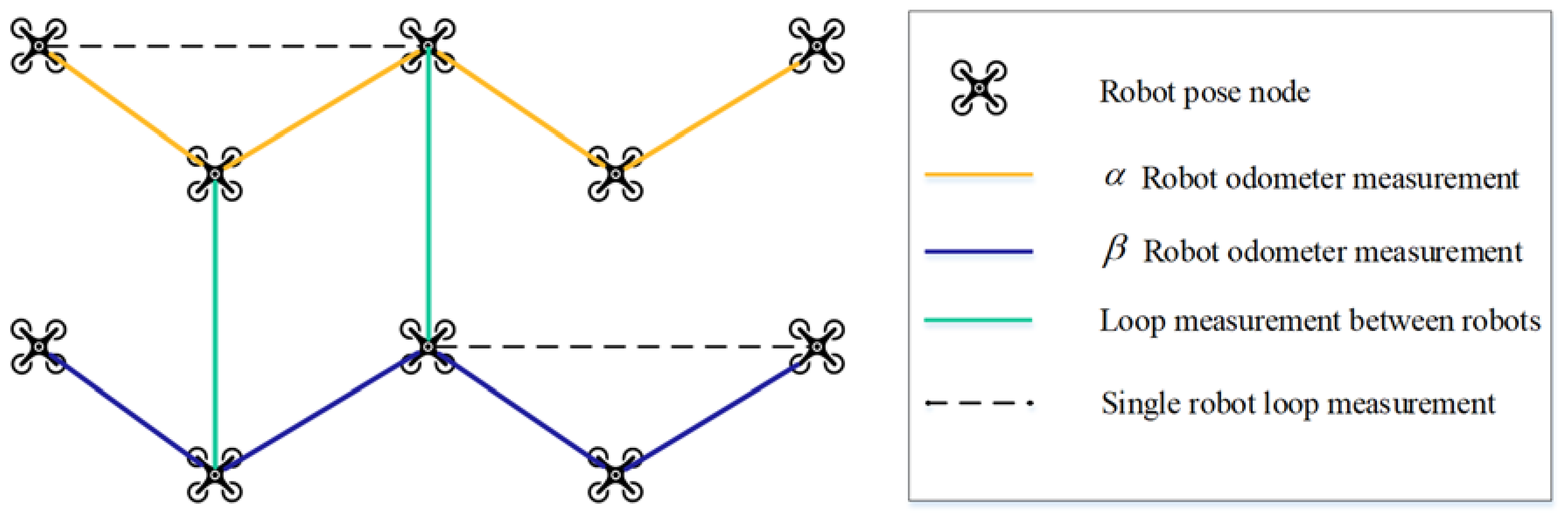
3.1. Pose Graph Model of Cooperative Robots

The relative pose measurements in the multi-robot pose graph model are divided into three types, as shown in Figure 2:
(1)
The odometer measurements for different robots α and β are represented using the solid yellow lines and solid blue ones respectively in Figure 2, denoted as symbols Z i j α and   Z i j β where j = i + 1 , and the set of odometer measurements are recorded as Z o d α and Z o d β ;
(2)
The loop closure in a single robot is represented by a dotted line in Figure 2, the corresponding symbols are Z i j α and Z i j β , and   j i + 1 , and the set of loop-closure in a single robot is recorded as Z l c α and Z l c β . Loop closures can be detected using appearance-based loop closing approaches that work following the bag of words approach [4];
(3)
The relative pose measurements between different robots are marked with solid green lines with the symbol Z i j α β in Figure 2, and the set of loop-closure between different robots is recorded as Z i j α β . Calculating relative position between robots is similar in nature to finding loop closures in the single robot problem: both of them involve comparing a query scan to a set of cached scans. The distinction is that the query scan in the former problem is received from a different robot [28].
To run global optimization, the transformation from each local coordinate system of different robots to the global coordinate system could be treated as an optimization variable [29]. Based on the above definition, the pose graph optimization problem of the multi-robot collaborative SLAM system can be described using a maximum likelihood estimation problem
X ^ , Δ ^   g = argmax X , Δ g   P ( Z α , Z β , Z α β   |   X , Δ g )
where X represents the trajectories of all robots, Z   means the set of measuring edges of all robots, and Δ g is the set of anchor nodes. In this way, the optimal pose node to be estimated can be solved according to the measured values. Generally, to solve the above likelihood estimation problem, it can be further transformed into a weighted least squares problem and solved by the mainstream solver. However, as shown in Figure 1 in the introduction, false positive loop closure with low proportion could cause completely wrong results. To improve the accuracy of the optimization results, the key point is the way to eliminate or minimize the impact of perceptual aliasing on the optimization results. Developing the perfect SLAM front-end that produces graphs that are free of outliers is generally impractical because of perceptual aliasing and perceptual variability. Therefore, optimization back-ends need to be able to deal with outliers resulting from an imperfect front-end. In this paper, our research is focused on using the consistency checking method based on the χ 2 test to reject false positive loop closures in order to improve the accuracy and robustness of collaborative SLAM systems.

3.2. Consistency Checking of Loop-Closures Based on χ 2 Test

As shown in Figure 2, the transformation which is represented as dotted line between the measured value and the estimated value of the relative pose transformation of two nodes i and j of the robot α is denoted as e i j ( z α ) , and the information matrix of the measured value is described using Ω i j , then the Mahalanobis distance can be described as
d i j 2 ( z α ) = e i j ( z α ) T Ω i j e i j ( z α )
According to the maximum likelihood estimation theory, the solution of the pose graph optimization is the one that minimizes the sum of Mahalanobis distances of all errors; therefore, the SLAM optimization problem is turned to the task of finding out those pose nodes satisfying the following condition.
x ^ α = argmin D 2 ( z α ) = argmin e i j ( z α ) T Ω i j e i j ( z α )
As known, the χ 2 test is a statistical hypothesis test being valid to perform when the test statistic is χ 2 distributed under the null hypothesis, in which the χ 2 value is computed according to the actual difference between the determined data. Specific to our method, if the calculated χ 2 value is greater than the theoretical value under a certain probability standard, then the corresponding measured value needs to be rejected.
In this paper, the false positive loop-closure detection and pose optimization algorithm in a multi-robot SLAM system is divided into two stages by using the above χ 2 test results based on consistency checking: (1) reject the false positive loop closure for each individual robot in the first stage; (2) reject the false positive loop closure between cooperative robots using the results of the first step. Figure 3 shows a flow chart of this algorithm.
Considering the loop-closure measurement distribution in the real scene has temporal continuity [16], the loop closure in a single robot is clustered incrementally. We determine whether a loop closure is false positive according to the results of the following three consistency checks: (1) the consistency of a single loop measurement subset; (2) the consistency between multiple loop-closure measurement subsets; and (3) the pairwise mutual consistency of loop measurement between robots using the local reliability information of the odometer measurement.
In our approach, the first step is to remove those false positive loop closures which fail to pass the first two types of consistency check, and the second step is to eliminate those false positive loop closures which fail to pass the last type of consistency check using the PCM algorithm based on the maximum clique. These two-stage error elimination methods are introduced in detail below.

3.3. First Step of Error Rejection: Rejection of Intra-Robot False Positive Loop-Closures

To distinguish between the odometer measurement and the loop-closure detection in Equation (3), the objective function can be written as
D 2 = z α Z o d α d i j 2 ( z α ) + z α Z l c α d i j 2 ( z α ) = z α Z o d α d i j 2 ( z α ) o d o m e t e r s + k = 1 n z α Z l c k α d i j 2 ( z α ) l o o p C l o s u r e s
Equation (5) divides the loop-closures into several subsets using the nature of time-series continuity of the loop-closures distribution in the real scene described in the literature [16] to perform clustering operations incrementally (that is, the process of dividing subsets), and the detailed steps are as follows:
  • Generate a set U to be inserted;
  • For each newly detected loop-closure detection Z i j α , verify whether it belongs to U according to Formula (5), and insert it if it does; otherwise, use all the measurement values in U to generate a new cluster, then clear U and insert Z i j α into U;
  • If there is no loop-closure detected, use the detection value in U to generate a new subset to complete the clustering.
After the clustering process, the k-th class in the loop-closure set satisfies the following conditions:
z i j α Z l c k α z p q α Z l c k α   s . t .   t i t p t g t j t q t g
where t i and t j represent the timestamp of the pose node connected by the newly detected loop-closure detection value respectively, t p and t q represent the two timestamps corresponding to the loop-closure detection value in the set U, t g represents the maximum time interval of the loop-closure detection value in a single subset. After clustering, the loop-closure detection set can be expressed as Z l c α = U k = 1 n Z k c k α and satisfying ( k l ) Z l c k α   Z l c l α = . Since the Mahalanobis distances of k independent standard normal distribution variables obey the χ 2 distribution; according to Equation (4), assuming that the error caused by the odometer is zero or infinitely close to zero, then when the iterative method is used to minimize the objective function, the pose node will be continuously updated as an optimization variable.
Due to the constraints introduced by those false positive loop closures, the value of the pose node will drift from the correct value, while the constraint added by the correct loop closure with a smaller error makes this deviation smaller. In a word, the determination of the consistency depends on the following precondition: although the odometer will have accumulated errors over time, with the nature of local reliability, it is still far smaller than the error caused by the perception deviation, so it can be used for judging whether the loop-closure detection is the perceptual aliasing. The concept of consistency can be further divided into the following two categories:
  • Consistency of a single loop-closure detection subset, which means that the sum of the Mahalanobis distance measured by a single loop-closure subset and the odometer passes the χ 2 test;
  • Consistency among multiple loop-closure subsets. Since the optimization direction of the loop-closure subset with larger errors is inconsistent with the correct loop closure due to the wrong place recognition result. Therefore, it can be judged whether the set of multiple loop-closure detection subsets and the sum of the Mahalanobis distance measured by the odometer can pass the χ 2 test. If not, we need to find the subset that does not satisfy the consistency judgment standard in this loop-closure detection subset and reject it as a whole. The detailed steps will be explained in the consistency check algorithm between subsets.
To satisfy consistency condition (1), the loop-closure of a single subset Z l c k α needs to satisfy the following conditions:
D G 2 = z α Z o d α d i j 2 ( z α ) + z α Z l c k α d i j 2 ( z α ) 2 < χ d G 2
D l 2 = e i j ( z α ) T Ω i j e i j ( z α ) < χ d l 2 , z α Z l c k α
where, D G and D l represent the error terms corresponding to the degree of freedom of the measured value contained in the said equations, which means they should be less than the set threshold based on the χ 2 test theoretically. If Equation (7) is not satisfied in the χ 2 test, the entire subset will be removed. In addition, the χ 2 test results of Equation (6) can be used to reject single inconsistent loop closure in the subset. According to the above consistency test conditions, the consistency check algorithm in a single loop-closure subset is given by Algorithm 1.
Algorithm 1. Check Algorithm inside Loop-closure Subsets
Input: - pose nodes, odometer measurements, loop-closure subset clusteri
Output: - single loop-closure measurement subset
(1)
Using pose nodes odometer measurements to construct PoseGraphOd
(2)
PoseGraphLc   PoseGraphOd;
(3)
Add clusteri to PoseGraphLc;
(4)
Optimize pose graph PoseGraphLc:
(5)
if   D G 2 < c d G 2   then :
(6)
for every loop-closure measurement edge loopclosure in cluster i do:
(7)
if   D l 2 < c d l 2   then :
(8)
cluster   {cluster, loopclosure};
(9)
else:
(10)
// formula (7) not satisfied, loop-closure need to be rejected
(11)
continue;
(12)
end if
(13)
end for
(14)
return cluster
(15)
else:
(16)
// formula (6) not satisfied, reject the entire loop-closure measurement subset
(17)
return cluster   {};
(18) 
end if
To satisfy the consistency condition (2), the collection of multiple loop-closure subsets must satisfy the following conditions:
D C 2 = k = 1 | C | z α Z l c k α d i j 2 ( z α ) 2 < χ d C 2
D G 2 = D C 2 + z α Z o d α e i j ( z α ) T Ω i j e i j ( z α ) < χ d G 2
Only when Equations (8) and (9) are satisfied at the same time, can the loop-closure subsets have consistency among them; otherwise, the loop-closure subset with the largest Mahalanobis distance is rejected, and then the consistency algorithm among loop-closure detection subsets is recursively called. The detailed process is described by Algorithm 2.
Algorithm 2. Checking consistency among loop-closure detection subsets
Input: - goodSet, candidateSet, PoseGraphOd which only contains pose nodes and odometer measurement
Output: - goodSet, rejectSet
(1)
PoseGraphLc   {PoseGraphOd, goodSet, candidateSet};
(2)
// Initialize rejection set to an empty set
(3)
rejectSet   {};
(4)
Optimize PoseGraphLc: ;
(5)
if   D C 2 < c d C 2 and D C 2 < c d C 2   then :
(6)
// All loop-closure can pass the consistency check
(7)
goodSet   {goodSet, candidateSet};
(8)
return goodSet, rejectSet;
(9) 
else:
(10)
find subset with largest Mahalanobis distance clusteri in candidateSet;
(11)
reject clusteri in candidateSet
(12)
rejectSet   {rejectSet, clusteri};
(13)
if candidateSet is not empty then:
(14)
{goodSet, rSet}
(15)
Recursively call consistency checking algorithm among loop-closure detection subsets;
(16)
rejectSet   {rejectSet, rSet};
(17)
end if
(18)
end if
(19) 
return goodSet, rejectSet;
The process of the first step of the error rejection algorithm is expressed by Algorithm 3.
Algorithm 3. The first step of the error rejection algorithm
Input: - pose nodes, Odometer measurements, Loop-closure subset C that includes Loop-closure
Output: - goodSet
(1)
Using pose nodes, Odometer measurements to construct PoseGraphOd;
(2)
Initialize consensus set to an empty set goodSet ←{};
(3)
Initialize rejection set to an empty set rejectSet←{};
(4)
while true do:
(5)
PoseGraphLc   PoseGraphOd;
(6)
currentSet C \ {goodSet   candidateSet};
(7)
Initialize candidate set to an empty set:candidateSet←{};
(8)
PoseGraphLc {PoseGraphLc, currentSet};
(9)
for every subset clusteri in candidateSet do:
(10)
Using Algorithm1 to check the consistency of clusteri
(11)
if subset is NOT empty then:
(12)
candidateSet   {candidateSet, clusteri}
(13)
end if
(14)
end for
(15)
if not candidateSet is empty then:
(16)
s = goodSet.size();
(17)
{goodSet, rSet}←
(18)
Recursively call consistency checking algorithm among loop-closure detection subsets;
(19)
if goodSet.size() > s then:
(20)
rejectSet {};
(21)
else:
(22)
rejectSet {rejectSet, rSet};
(23)
end if
(24)
else:
(25)
break;
(26)
end if
(27) 
end while:
Although it is a conservative approach to reject false positive loop-closures of a single robot based on the reliability of the local odometer measurement, since the entire subset of loops not satisfying the consistency condition will be fully rejected. However, as shown in Figure 1, we are more concerned about the negative impact of false positive loop-closures, it is a feasible approach to not retain all true positive loop-closures. Therefore, this algorithm is adopted as the first step of the error rejection method to complete the first two types of consistency checks.

3.4. The Second Step of Error Rejection: Reject False Positive Loop-Closure Detection among Cooperative Robots

Theoretically, in our approach, the false positive loop-closure detection between robots is based on the pairwise mutual consistency check algorithm of the largest group (PCM), and the χ 2 distribution is used to check the paired loop-closure mutual consistency between robots and then find the loop-closure subset with the largest mutual consistency and reject all others.
As it is known, PCM algorithm generally cannot keep 100% of all correct loop closures, but it can ensure the consistency of the loop-closure subset not being rejected, thereby ensuring that false positive loop-closure will not participate in the back-end optimization process. The principle of false positive loop-closure detection of PCM is as follows:
The principle of the PCM algorithm can be represented in Figure 4: the odometer measurements of single robot are indicated as a solid yellow line and a solid blue line respectively and the correct detected loop closures are indicated as solid green lines, the false loop closure is represented as a solid green line with a red arrow line above in Figure 4b. As shown in Figure 4a, when the measured value does not contain noise or a very small amount of noise, starting from the bottom left point of the initial pose can ‘return’ after calculating the result of the addition of two odometers and two loop-closures between robots on non-Euclidean space; when a false positive loop-closure happens, as shown in Figure 4b, generally there is a large error between the calculated pose and the initial pose (without mutual consistency). To measure the distance between the computed pose and the initial pose, which means to determine whether the paired loop-closures z j k α β and z i l α β satisfy the mutual consistency, the following conditions should be satisfied:
D I 2 = ( z i j α z j k α β z k l β ) z i l α β Σ < χ d z 2
where D I 2 represents the Mahalanobis distance of the computed pose error, Σ represents the covariance matrix of the computed poses, χ d 2 2 represents the χ 2 distribution corresponding to the degree of freedom d Z of the pose measurement edge, symbols and mean operations on the manifold, and the operational rules on 2-d and 3-d manifolds could refer to the literature [30].
For the loop-closure detection value between each robot, it is necessary to combine all loop-closures with other robots and complete the mutual consistency check, and then find the loop-closure subset that has the largest internal loop-closure with mutual consistency. The aforesaid process is with exponential time complexity, and it can be solved by transforming it into a maximum clique problem [31] in graph theory. As known, solving the maximum clique problem is an NP-hard problem, and the time cost of deterministic algorithms, such as backtracking and branch and bound method, increases exponentially with the problem size (the number of vertexes increases and the edge density increases) [32].
Heuristic algorithms—such as sequential greedy, DLS-MC, and intelligent search algorithm—could also be used to resolve the problem, and the ratio of computing time of heuristic algorithms to deterministic algorithms will get smaller and smaller with the increase of the vertex and edge density of the graph; however, heuristic algorithms sometimes can only obtain approximate optimal results.
Pattabiraman’s parallel method is applied [33] to actively cut the branches of the search tree, and PCM algorithm is used to execute the last type of consistency check to run the second-stage error rejection. The detailed description of the algorithm is as follows:
Through the above two-stage false positive loop-closure rejection method for single-robot and multi-robot systems, the pose of the collaborative SLAM system could be optimized based on the aforegiven pose graph optimization model. The second step of error rejection algorithm is presented by Algorithm 4.
Algorithm 4. Second step of error rejection algorithm
Input:- Pose nodes, odometer measurements, intra-robot loop closure set C that
Output: - Maximum mutual consistency set max_clique:
(1)
Using pose nodes, Odometer measurements to construct PoseGraphOd;
(2)
Creating a new set cliques and allocate space of size C.size;
(3)
cliques.size = C.size;
(4)
for loop in C:
(5)
creating empty set clique;
(6)
inserting loop into the collection clique;
(7)
for left loop in C \ loop: // for each other loops
(8)
if loop and left loop can be connected as shown in Figure 4:
(9)
Calculating whether the two loops satisfy mutual consistency through formula
(10)
if loop left loop satisfies mutual consistency:
(11)
inserting left loop into clique;
(12)
else:
(13)
// If the mutual consistency not satisfied, not added it
(14)
continue;
(15)
end if
(16)
end if
(17)
insert clique into cliques;
(18)
end for
(19)
end for
(20)
Using maximum clique to calculate the set with the largest number of loop-closure in cliques and assign it to max_clique;
(21)
return max_clique;

4. Experiments and Analysis

To evaluate the performance of the proposed algorithm, comparison experiments with the existing mainstream PCM method and its popular variants are designed and conducted using the open dataset and the synthetic data. The quantitative evaluation indexes include the rejection rate of false positive closure and the trajectory accuracy calculated after optimizing the rejected pose map. The two indexes to evaluate the accuracy of trajectory estimation are absolute translation error (ATE) and absolute rotation error (ARE), which are described using Equations (11) and (12).
ATE = ( 1 α N n α α i = 1 n α t ^ i α t i α 2 ) 1 2
ARE = ( 1 α N n α α i = 1 n α log ( ( R ^ i α ) T R i α ) 2 ) 1 2
where, t ^ t α   and t i α represent the real and estimated displacement vectors of robot α at time i respectively; R ^ i a and R i a represent the real and the estimated rotation matrixes, which are mapped to the rotation Lie algebra by log ( · ) V mapping. Our method is tested on the open dataset and the synthetic data respectively, and the results are compared with existing mainstream methods such as dynamic covariance scaling and PCM based on maximum clique to analyze the robustness of the algorithm to outliers and the accuracy of pose fusion. The test environment used is shown in the table below, and in our test only CPU is used.

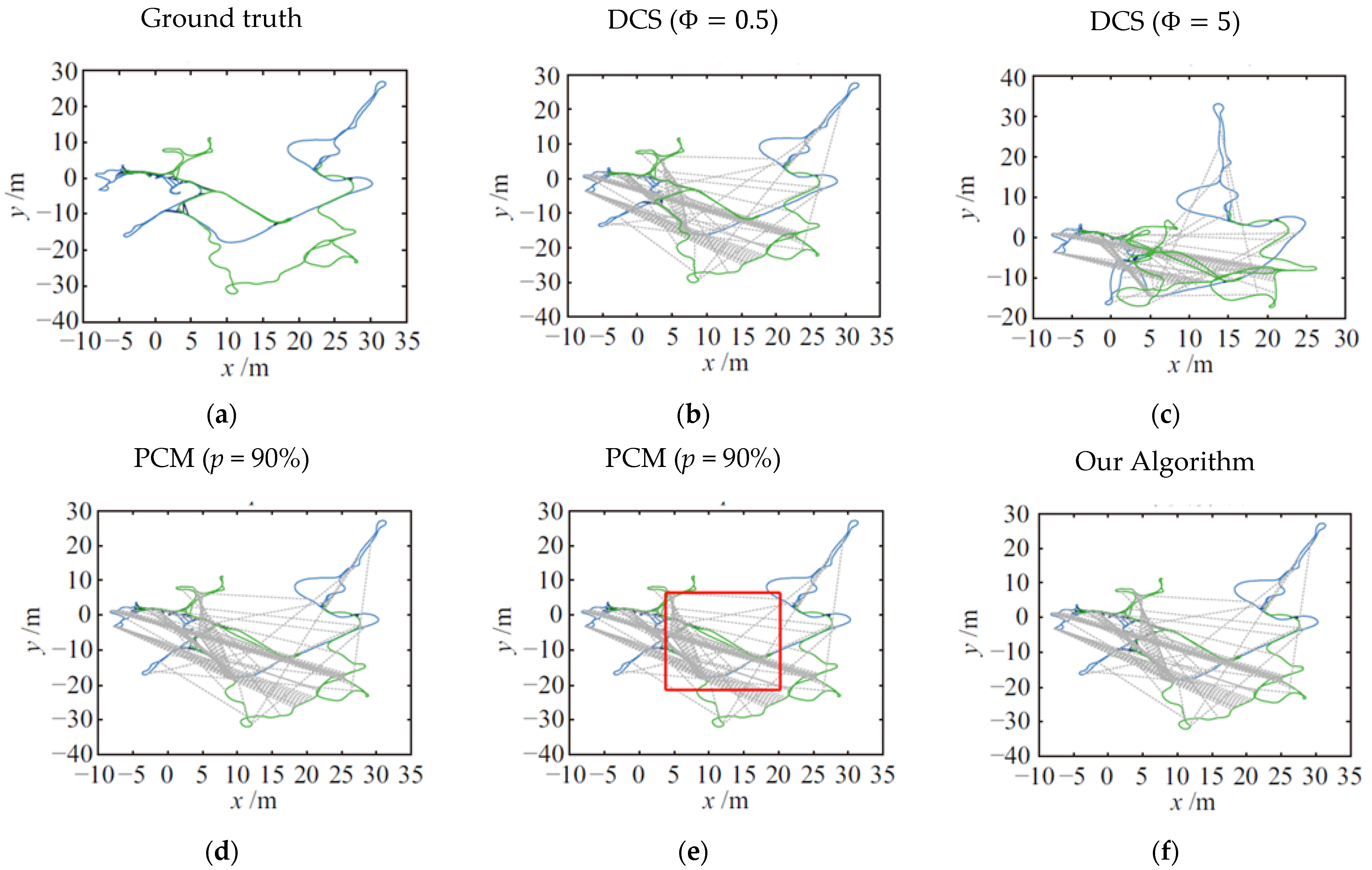
4.1. Test Using CSAIL Dataset

Open dataset CSAIL (MIT Computer Science and Artificial Intelligence Laboratory) is widely used in the computer vision community. The dataset is collected by laser scanning in the indoor scene of MIT Computer Science and Artificial Intelligence Laboratory building, and Carlone [34] generated a 2D graph file representing pose nodes and measurement edges in the dataset, which contains 1045 pose nodes and 1172 measurement edges (including 128 loop-closure detections). To represent the pose map of those cooperative robots, this dataset is cut into two robot pose datasets by us, in which the number of pose nodes of robot α is 522 and its loop measurement edges are 646. The number of pose nodes of robot β is 523, its loop measurement edge is 636, and there are 110 loop measurement edges between the two robots.
Outliers were generated according to the literature [16], and the outlier measurement edges between robots were added to the data set. Among them, multiple groups of mutually consistent abnormal edges are used to simulate the error loop-closure caused by perceptual aliasing, and the randomly added abnormal edges are used to simulate the influence of random noise.
Figure 5 and Table 1 show the comparison results of various algorithms when the proportion of abnormal measured values is 50%. The added edges include false positive loop-closures both from intra-individual and inter-individual robots. The optimal parameters of the DCS algorithm are obtained by analyzing the true value and initial value in advance Φ = 0.5. It can be seen from Figure 6 that when the parameter values of DCS and PCM algorithms are selected appropriately (in the upper and lower columns of Figure 6), the absolute position error and attitude error are small, mainly because the initial position and attitude error of CSAIL data set is small, and the odometer measurement is reliable, which satisfies the operation conditions of DCS and PCM algorithms better. The same parameters as PCM algorithm (p = 90%) are selected for our method. As shown in the red block diagram in Figure 6e, compared with PCM, the pose map fusion result of our algorithm in this paper.
A quantitative comparison results of ATE and ARE errors are given in Table 2. It could be found, when the abnormal measured percentage is 50%, that the absolute position error and attitude error value of our method are much less than those of DCS and PCM algorithms, and the position and attitude fusion accuracy of ours is the best.

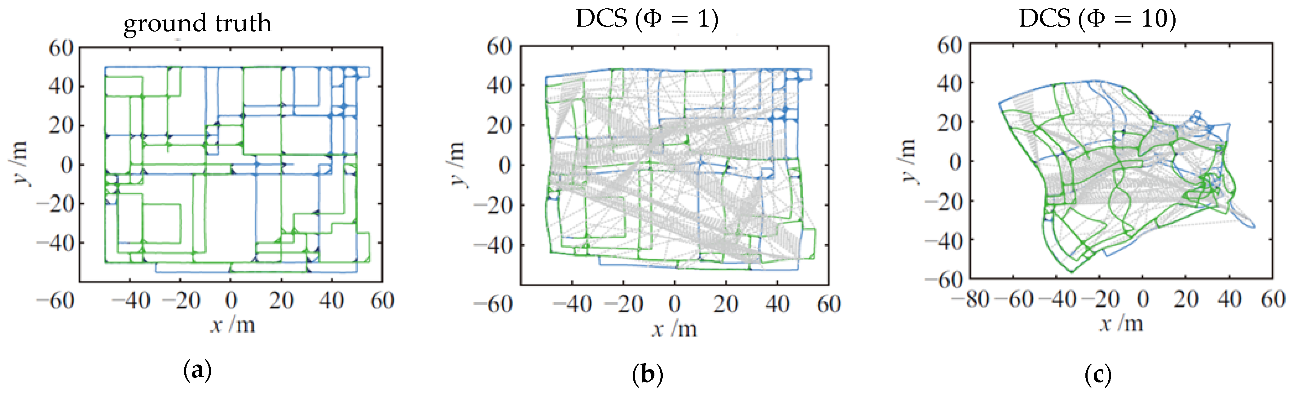
4.2. Validation Using Synthetic Data Sets

Another dataset used in our experiment is city10,000 which is a synthetic dataset published by Kaess and his collaborators [35]. In our test, the first 3000 pose nodes are used for experiments, and the data set is cut into two parts chronologically to simulate two different robot trajectories. Each part contains the robot’s pose nodes and measurement edges, and each robot trajectory data contains 1500 pose nodes. Robot α has 2571 its measurement edges and robot β has 2382 its measurement edges. There are 626 loop-closures between the two robots. The original pose diagram is shown in Figure 7.
Figure 8 shows the test results of each algorithm with 50% anomalies, including 20 sets of consecutive anomalous edges (10 edges as a set) and 100 random anomalous edges, where the thin blue and green lines indicate the odometer trajectories of the two robots, the thick blue and green lines indicate the loop-closure measurements on the robot’s own trajectory, the thick dark blue line indicates the normal loop-closure measurements between robots, and the gray dashed line represents the added anomalous loop-closure edges. The parameters of the DCS and PCM algorithms were set through a prior comparative analysis of the true values, and they are Φ { 1 , 10 } , p = 90%. The optimal parameter corresponding to the DCS algorithm on this synthetic dataset is set as = 1 according to [17].
As shown in Figure 8b, even with the optimal parameter setting, the positional fusion results of DCS ( Φ = 1 ) are still with large error, and in the red box of Figure 8e, the PCM algorithm still has a large gap in the accuracy of the fused poses since no false-positive loop closure is rejected for an individual robot.
From the results of position and pose error of each algorithm on the City10,000 data set in Table 2 and Figure 8a–f, one can see that: (1) the DCS algorithm is less effective, however the position error still reaches 5.6 m even when the parameters are adjusted to the optimal value; (2) the PCM algorithm still has a large gap with the true value under the condition of 90% confidence level; (3) with the confidence level being the same as that of PCM, the accuracy of position and pose estimation of our algorithm are much better than that of DCS and PCM.
In Table 3, it could be found that the performance of DCS algorithm highly relies on the initial parameter setting, and it is very difficult to select initial parameters without sufficient a priori information. The PCM algorithm relies on reliable odometer measurements to filter normal values, and the fused positional accuracy is poor without prior false-positive loop-closure rejection for individual robots. Overall, our proposed approach shows better robustness to outlier data, and can provide more precise results.

5. Conclusions and Prospects

It is generally an impossible mission to develop a perfect SLAM-end free of false positive loop-closure due to perceptual aliasing and perceptual variability, while the outliers can highly affect the accuracy and robustness. However, for a collaborative SLAM system that generally uses both intra and inter loop closures to optimize pose graph, it is difficult to reject those false positive loop closures without reliable a priori knowledge of the relative pose transformation among robots. Aiming at solving this problem, this paper proposes a two-stage false positive loop-closure rejection method based on three types of consistency checks that can be embedded in the collaborative SLAM system. Three kinds of consistency check methods were proposed: the first step of our algorithm is to eliminate the outlier loop-closures that fail the first two kinds of consistency check; the second step is to reject the false positive loop-closure between robots failing the last kind of consistency check, with the pairwise mutual consistency check algorithm based on the maximum clique. The experiments indicate that this method does not rely on a priori relative pose measurement: when the proportion of outliers is 50%, it has very good performance in restoring the original multi-robot trajectories, and the fusion accuracy is better than that of existing mainstream DCS and PCM methods. Our method can be directly embedded into the back-end of real-time collaborative SLAM systems—such as CCM-SLAM [36] and CVI-SLAM [37]—to improve their system robustness and accuracy. Future studies will be focused on points such as accelerating false positive loop-closure rejection process and integration with other sensors. Moreover, our method is currently offline and tested in public datasets and the focus of the algorithm is to eliminate false positive loops and improve accuracy. Due to the two-stage strategy, there is no advantage in time compared with PCM and DCS, so developing methods for using the proposed algorithm in an incremental fashion would also be one of our plans for future work.

Author Contributions

Conceptualization, X.Z. and Q.W.; Methodology, X.Z. and Z.Z.; Software, Z.Z. and X.Z.; Data curation, X.Z. and Y.Y.; Writing—original draft preparation, X.Z. and Z.Z.; Writing—review and editing, X.Z. and Q.W.; Supervision, X.Z.; Project administration, X.Z. and Y.Y.; Funding acquisition, X.Z. and Q.W. All authors have read and agreed to the published version of the manuscript.

Funding

This research was funded by the National Key Technologies R&D Program of China, grant no. 2020YFD1100201 and the National Natural Science Foundation of China, grant no. 62073078.

Institutional Review Board Statement

Not applicable.

Informed Consent Statement

Not applicable.

Data Availability Statement

Not applicable.

Acknowledgments

The authors would like to give thanks for the support from Jiangsu Overseas Visiting Scholar Program for University Prominent Young and Middle-aged Teachers and Presidents.

Conflicts of Interest

The authors declare no conflict of interest.

References

  1. Zou, D.; Tan, P.; Yu, W. Collaborative visual SLAM for multiple agents:A brief survey. Virtual Real. Intell. Hardw. 2019, 1, 461–482. [Google Scholar] [CrossRef]
  2. Yu, K.; Ahn, J.; Lee, J.; Kim, M.; Han, J. Collaborative SLAM and AR-guided navigation for floor layout inspection. Vis. Comput. 2020, 36, 2051–2063. [Google Scholar] [CrossRef]
  3. Ouyang, M.; Shi, X.; Wang, Y.; Tian, Y.; Shen, Y.; Wang, D.; Wang, P.; Cao, Z. A Collaborative Visual SLAM Framework for Service Robots. arXiv 2021, arXiv:2102.03228. [Google Scholar]
  4. G Alvez-L Opez, D.; Tard Os, J.D. Bags of Binary Words for Fast Place Recognition in Image Sequences. IEEE Trans. Robot 2012, 28, 1188–1197. [Google Scholar] [CrossRef]
  5. Campos, C.A.E.R. ORB-SLAM3: An Accurate Open-Source Library for Visual, Visual-Inertial and Multi-Map SLAM. arXiv 2020, arXiv:2007.11898. [Google Scholar]
  6. Qin, T.; Pan, J.; Cao, S.; Shen, S. A General Optimization-based Framework for Local Odometry Estimation with Multiple Sensors. arXiv 2019, arXiv:1901.03638. [Google Scholar]
  7. Kaess, M.; Johannsson, H.; Roberts, R.; Ila, V.; Leonard, J.; Dellaert, F. iSAM2: Incremental smoothing and mapping with fluid relinearization and incremental variable reordering. In Proceedings of the IEEE International Conference on Robotics and Automation, Shanghai, China, 9–13 May 2011; pp. 3281–3288. [Google Scholar]
  8. Mangelson, J.G.; Dominic, D.; Eustice, R.M.; Vasudevan, R. Pairwise Consistent Measurement Set Maximization for Robust Multi-Robot Map Merging. In Proceedings of the 2018 IEEE International Conference on Robotics and Automation (ICRA), Brisbane, QLD, Australia, 21–25 May 2018; pp. 2916–2923. [Google Scholar]
  9. Grisetti, G.; Kümmerle, R.; Stachniss, C.; Burgard, W. A Tutorial on Graph-Based SLAM. IEEE Intell. Transp. Syst. Mag. 2010, 2, 31–43. [Google Scholar] [CrossRef]
  10. Prados Sesmero, C.; Villanueva Lorente, S.; Di Castro, M. Graph SLAM Built over Point Clouds Matching for Robot Localization in Tunnels. Sensors 2021, 21, 5340. [Google Scholar] [CrossRef]
  11. Garg, S.; Sünderhauf, N.; Dayoub, F.; Morrison, D.; Cosgun, A.; Carneiro, G.; Wu, Q.; Chin, T.; Reid, I.; Gould, S.; et al. Semantics for Robotic Mapping, Perception and Interaction: A Survey. Found. Trends Robot. 2020, 8, 1–224. [Google Scholar] [CrossRef]
  12. Kümmerle, R.; Grisetti, G.; Strasdat, H.; Konolige, K.; Burgard, W. G2o: A general framework for graph optimization. In Proceedings of the 2011 IEEE International Conference on Robotics and Automation, Shanghai, China, 9–13 May 2011; pp. 3607–3613. [Google Scholar]
  13. Dellaert, F.; Kaess, M. Factor Graphs for Robot Perception; Now Foundations and Trends: Hanover, MA, USA, 2017; p. 154. [Google Scholar]
  14. Grisetti, G.; Kümmerle, R.; Stachniss, C.; Frese, U.; Hertzberg, C. Hierarchical optimization on manifolds for online 2D and 3D mapping. In Proceedings of the 2010 IEEE International Conference on Robotics and Automation, Anchorage, AK, USA, 3–7 May 2010; pp. 273–278. [Google Scholar]
  15. Tzoumas, V.; Antonante, P.; Carlone, L. Outlier-Robust Spatial Perception: Hardness, General-Purpose Algorithms, and Guarantees. In Proceedings of the 2019 IEEE/RSJ International Conference on Intelligent Robots and Systems (IROS), Macau, China, 3–8 November 2019; pp. 5383–5390. [Google Scholar]
  16. Sünderhauf, N.; Protzel, P. Switchable constraints for robust pose graph SLAM. In Proceedings of the 2012 IEEE/RSJ International Conference on Intelligent Robots and Systems, Vilamoura-Algarve, Portugal, 7–12 October 2012; pp. 1879–1884. [Google Scholar]
  17. Agarwal, P.; Tipaldi, G.D.; Spinello, L.; Stachniss, C.; Burgard, W. Robust map optimization using dynamic covariance scaling. In Proceedings of the 2013 IEEE International Conference on Robotics and Automation, Karlsruhe, Germany, 6–10 May 2013; pp. 62–69. [Google Scholar]
  18. Carlone, L.; Censi, A.; Dellaert, F. Selecting good measurements via ℓ1 relaxation: A convex approach for robust estimation over graphs. In Proceedings of the 2014 IEEE/RSJ International Conference on Intelligent Robots and Systems, Chicago, IL, USA, 14–18 September 2014; pp. 2667–2674. [Google Scholar] [CrossRef]
  19. Mazuran, M.; Diego Tipaldi, G.; Spinello, L.; Burgard, W.; Stachniss, C. A statistical measure for map consistency in SLAM. In Proceedings of the 2014 IEEE International Conference on Robotics and Automation (ICRA), Hong Kong, China, 31 May–7 June 2014; pp. 3650–3655. [Google Scholar]
  20. Lajoie, P.; Ramtoula, B.; Chang, Y.; Carlone, L.; Beltrame, G. DOOR-SLAM: Distributed, Online, and Outlier Resilient SLAM for Robotic Teams. IEEE Robot. Autom. Lett. 2020, 5, 1656–1663. [Google Scholar] [CrossRef] [Green Version]
  21. Wu, F.; Beltrame, G. Cluster-based Penalty Scaling for Robust Pose Graph Optimization. IEEE Robot. Autom. Lett. 2020, 5, 6193–6200. [Google Scholar] [CrossRef]
  22. Latif, Y.; Cadena, C.; Neira, J. Robust loop closing over time for pose graph SLAM. Int. J. Robot. Res. 2013, 32, 1611–1626. [Google Scholar] [CrossRef]
  23. Neira, J.; Tardos, J.D. Data association in stochastic mapping using the joint compatibility test. IEEE Trans. Robot. Autom. 2001, 17, 890–897. [Google Scholar] [CrossRef] [Green Version]
  24. Lajoie, P.; Hu, S.; Beltrame, G.; Carlone, L. Modeling Perceptual Aliasing in SLAM via Discrete–Continuous Graphical Models. IEEE Robot. Autom. Lett. 2019, 4, 1232–1239. [Google Scholar] [CrossRef] [Green Version]
  25. Chang, Y.; Tian, Y.; How, J.P.; Carlone, L. Kimera-Multi: A System for Distributed Multi-Robot Metric-Semantic Simultaneous Localization and Mapping. arXiv 2020, arXiv:2106.14386. [Google Scholar]
  26. Rosinol, A.; Abate, M.; Chang, Y.; Carlone, L. Kimera: An Open-Source Library for Real-Time Metric-Semantic Localization and Mapping. In Proceedings of the 2020 IEEE International Conference on Robotics and Automation (ICRA), Paris, France, 31 May–31 August 2020; pp. 1689–1696. [Google Scholar]
  27. Do, H.; Hong, S.; Kim, J. Robust Loop Closure Method for Multi-Robot Map Fusion by Integration of Consistency and Data Similarity. IEEE Robot. Autom. Lett. 2020, 5, 5701–5708. [Google Scholar] [CrossRef]
  28. Dong, J.; Nelson, E.; Indelman, V.; Michael, N.; Dellaert, F. Distributed real-time cooperative localization and mapping using an uncertainty-aware expectation maximization approach. In Proceedings of the 2015 IEEE International Conference on Robotics and Automation (ICRA), Seattle, WA, USA, 26–30 May 2015; pp. 5807–5814. [Google Scholar]
  29. Kim, B.; Kaess, M.; Fletcher, L.; Leonard, J.; Bachrach, A.; Roy, N.; Teller, S. Multiple relative pose graphs for robust cooperative mapping. In Proceedings of the 2010 IEEE International Conference on Robotics and Automation, Anchorage, AK, USA, 3–7 May 2010; pp. 3185–3192. [Google Scholar]
  30. Smith, R.; Self, M.; Cheeseman, P. Estimating Uncertain Spatial Relationships in Robotics. In Proceedings of the 1987 IEEE International Conference on Robotics and Automation, Raleigh, NC, USA, 31 March–3 April 1987. [Google Scholar]
  31. Wu, Q.; Hao, J. A review on algorithms for maximum clique problems. Eur. J. Oper. Res. 2015, 242, 693–709. [Google Scholar] [CrossRef]
  32. Bomze, I.M.; Budinich, M.; Pardalos, P.M.; Pelillo, M. The maximum clique problem. In Handbook of Combinatorial Optimization; Springer: Berlin/Heidelberg, Germany, 1999; pp. 1–74. [Google Scholar]
  33. Pattabiraman, B.; Patwary, M.M.A.; Gebremedhin, A.H.; Liao, W.; Choudhary, A. Fast Algorithms for the Maximum Clique Problem on Massive Graphs with Applications to Overlapping Community Detection. Internet Math. 2015, 11, 421–448. [Google Scholar] [CrossRef] [Green Version]
  34. Carlone, L.; Aragues, R.; Castellanos, J.A.; Bona, B. A fast and accurate approximation for planar pose graph optimization. Int. J. Robot. Res. 2014, 33, 965–987. [Google Scholar] [CrossRef]
  35. Kaess, M.; Ranganathan, A.; Dellaert, F. iSAM: Incremental Smoothing and Mapping. IEEE Trans. Robot. 2008, 24, 1365–1378. [Google Scholar] [CrossRef]
  36. Schmuck, P.; Chli, M. CCM-SLAM: Robust and efficient centralized collaborative monocular simultaneous localization and mapping for robotic teams. J. Field Robot. 2018, 36, 763–781. [Google Scholar] [CrossRef] [Green Version]
  37. Karrer, M.; Schmuck, P.; Chli, M. CVI-SLAM—Collaborative Visual-Inertial SLAM. IEEE Robot. Autom. Lett. 2018, 3, 2762–2769. [Google Scholar] [CrossRef] [Green Version]
Figure 1. The impact of false positive loop closures to optimization results. (a) The original pose graph without optimization; (b) The optimized result of the original pose graph using g2o; (c) The pose graph with only 1% false positive loop edges randomly added (in red color); (d) The optimized result of (c) using g2o.
Electronics 10 02638 g001
Figure 2. Multi-robot pose diagram optimization model.
Electronics 10 02638 g002
Figure 3. Flow chart of two-stage error elimination method.
Electronics 10 02638 g003
Figure 4. Schematic diagram of PCM algorithm. (a) In the correct loop-closure, a robot returns to the starting point after pose transformation; (b) A false positive loop-closure, which is unable to return to the starting point after pose transformation.
Electronics 10 02638 g004
Figure 5. Trajectories of the original CSAIL dataset after cutting, and the solid green line and solid blue line in the figure represent the odometer measurement of the two robots respectively.
Electronics 10 02638 g005
Figure 6. Comparison of pose fusion results on CSAIL dataset. (a) Ground truth of CSAIL data set; (b) Optimization result using DCS algorithm with Φ = 0.5 ; (c) Optimization result using DCS algorithm with Φ = 5 ; (d) Optimization result using PCM algorithm with p = 90%; (e) Optimization result using PCM algorithm with p = 90%, the red box indicates the difference from ground truth; and (f) Optimization result using our algorithm.
Electronics 10 02638 g006
Figure 7. City10,000 synthetic dataset. The solid green line and solid blue line in the figure represent the odometer measurement of the two robots α and β respectively.
Electronics 10 02638 g007
Figure 8. Comparison of pose fusion results of various algorithms in City10,000 dataset. (a) Ground truth of City10,000 data set; (b) Optimization result using DCS algorithm with Φ = 1 ; (c) Optimization result using DCS algorithm with Φ = 10 ; (d) Optimization result using PCM algorithm with p = 90%; (e) Optimization result using PCM algorithm with p = 90%, the red box indicates the difference from ground truth; (f) Optimization result using our algorithm.
Electronics 10 02638 g008aElectronics 10 02638 g008b
Table 1. Hardware and software configuration of the experiment.
NameConfiguration
CPUIntel [email protected] GHz
Memory32 GB
OSUbuntu 18.04
Software environmentVSCode, GTSAM4.0.3
Table 2. ATE and ARE errors of algorithms on the CSAIL dataset.
ATE/mARE/rad
Initial value1.7920.082
DCS (Φ = 0.5)0.1860.022
DCS (Φ = 5)14.7870.673
PCM (p = 90%)1.3480.198
Our algorithm (p = 90%)0.0950.008
Table 3. ATE and ARE errors of algorithms in CSAIL dataset.
ATE/mARE/rad
Initial value15.2660.276
DCS (Φ = 1)5.6880.149
DCS (Φ = 10)34.7151.067
PCM (p = 90%)1.0940.145
Our algorithm (p = 90%)0.1260.004
Publisher’s Note: MDPI stays neutral with regard to jurisdictional claims in published maps and institutional affiliations.

