Article

Miniaturized Broadband-Multiband Planar Monopole Antenna in Autonomous Vehicles Communication System Device

Department of Electronic Engineering, National Taipei University of Technology, Taipei City 10608, Taiwan
*
Author to whom correspondence should be addressed.
Electronics 2021, 10(21), 2715; https://doi.org/10.3390/electronics10212715
Submission received: 13 October 2021 / Revised: 3 November 2021 / Accepted: 5 November 2021 / Published: 8 November 2021
(This article belongs to the Special Issue Recent Advances in Antenna Design for 5G Heterogeneous Networks)

Abstract

:
The article mainly presents that a simple antenna structure with only two branches can provide the characteristics of dual-band and wide bandwidths. The recommended antenna design is composed of a clockwise spiral shape, and the design has a gradual impedance change. Thus, this antenna is ideal for applications also recommended in these wireless standards, including 5G, B5G, 4G, V2X, ISM band of WLAN, Bluetooth, WiFI 6 band, WiMAX, and Sirius/XM Radio for in-vehicle infotainment systems. The proposed antenna with a dimension of 10 × 5 mm is simple and easy to make and has a lot of copy production. The operating frequency is covered with a dual-band from 2000 to 2742 MHz and from 4062 to beyond 8000 MHz and, it is also demonstrated that the measured performance results of return loss, radiation, and gain are in good agreement with simulations. The radiation efficiency can reach 91% and 93% at the lower and higher bands. Moreover, the antenna gain can achieve 2.7 and 6.75 dBi at the lower and higher bands, respectively. This antenna design has a low profile, low cost, and small size features that may be implemented in autonomous vehicles and mobile IoT communication system devices.

1. Introduction

The vigorous development of IoT technology has laid a solid foundation for continued growth in the 5G era [1,2]. Therefore, networking, artificial intelligence, virtual reality (VR), and augmented reality (AR) technology can be used to provide relevant local 5G-centered services in health care, education, and other fields [3,4]. The rise of 5G communications has initiated various IoT business model development. The driving factors that trigger IoT applications include the low cost of storing and computing data on cloud platforms. In addition, it also includes emerging edge computing trends, the decline in data, sensors, equipment costs, and the availability of mobile application development platforms [5]. Therefore, emerging technologies integrate intelligent roads, intelligent vehicles, and artificial intelligence into our lives [6]. Therefore, 5G technology still has a lot to be discussed and technical improvement, combined with other wireless communication technologies, and continues to improve wireless communication development in Beyond 5G (B5G). Large-scale low-latency internet of things and 5G private network services focus on the next generation of B5G/6G development. Therefore, the spectrum planning and telecommunication service mode of B5G satellite communications will be essential in the future. The use of low-orbit satellites is expected to supplement areas that ground base stations cannot cover and through 5G/B5G/emerging wireless communication, vertical application demonstrations, IoT devices, and scenarios are introduced to provide innovative applications [7,8].
Furthermore, low-orbit satellite communication is also a key technology for future 6G commercial transformation. The development of 5G technology to 6G and satellite communications also includes the evolution of existing technologies and the development of emerging technologies for terrestrial communications, which will generate demand for spectrum planning [7,9]. In addition, the rapid progress of telecommunications infrastructure will affect the future development of artificial intelligence and self-driving vehicles.
The current internet of things devices must have a good match with wireless communication. However, the antenna design requires a design with multiple frequency bands and a large bandwidth is the same basic design principle. The main reason is that various wireless communication design standards must be accommodated in one device [10,11,12].
In recent literature discussion, antenna design is mostly compact multi-band antenna design as the main discussion topic. The superior design of coplanar waveguide (CPW) and slot line antenna (SL) can be used to achieve antenna design goals, including easy manufacturing and high compatibility with microwave circuits. In addition, using the CPW architecture design, CPW line segments with different widths and gap widths are used to achieve the ideal resonance frequency and massive bandwidth [13,14,15].
Multi-band antennas have integrated the applications of multiple wireless communication standards. It can be seen that the antenna design of IoT mobile devices with multi-band operation capabilities will be in great demand in the future market. Therefore, many design and development methods have been extended to multi-band antennas and integrated into various wireless communication product applications. However, the antenna design can be implemented in multiple frequency bands with antenna size minimization. Different generating frequency bands have been proposed in a single antenna, such as double L-slit, inductive slot [16,17,18,19,20,21,22,23,24,25].
The design of IoT electronic products requires miniaturization and compact circuit design. Therefore, the antenna design space must be sacrificed. However, the antenna’s effectiveness still needs to reach a certain level—no matter what kind of wireless communication product, finding any possible design practice is an important issue.
This research article mainly presented a miniaturized broadband-multiband planar monopole antenna with a clockwise spiral shape of two branches for Beyond-5G, 5G, 4G, V2X, DSRC, WiFi 6 band, WLAN, and WiMAX application in autonomous vehicles and mobile IoT communication system device.

2. Recommended Monopole Antenna Construction

The recommended antenna structure is disclosed and presented in Figure 1—the proposed antenna design with the best characteristic, including small size, broadband bandwidth, and low-profile structure. The proposed antenna employed a clockwise spiral shape of two branches to achieve dual-band performance covering 2000 to 2742 MHz and 4062 to over 8000 MHz, as shown in Figure 1a,e. The proposed antenna is validated by a mini coaxial cable with the characteristic impedance of 50 ohms and connects to an SMA connector, as shown in Figure 1a. This design is suitable for eight novel wireless communication systems, including Beyond-5G for LEO Device to Device (D2D) application, 5G, 4G, V2X, DSRC, WiFi 6 band, WLAN, and WiMAX systems. The antenna material is simulated and fabricated using the most commonly used FR4 substrate in the industry, as shown in Figure 1b. The antenna area is placed on the edge side in a device design, and the related wireless and baseband function components for the vehicle applications will be designed in the ground plane to combine the antenna design. The design parameters of the FR4 substrate are with the dielectric constant (εr) of 4.4, the dielectric loss tangent of 0.00245, and the height of 0.8mm.
The main antenna area with the dimension of 10 × 7.5 mm, and the ground for system placement includes an integrated circuit with power, baseband, and wireless transceiver function, which is located the dimension of 10 × 42.5 mm, as the detailed information displayed in Figure 1a–c. The actual antenna photo produced is shown in Figure 1d. The antenna design only needs the top surface to complete the design. Therefore, the tolerance sensitivity of this design is low, and it is easy to adjust the accurate operating frequency design. In addition, the clockwise spiral shape of two branches has defined Strip 1 and Strip 2 to explain the physical phenomena of surface current distribution analysis and resonance frequency, as shown in Figure 1e.
The surface current distribution is analyzed in Figure 2. The lower band is displayed at 2350 and 2450 MHz in Figure 2a,b. The upper band at 5080, 5500, 5890, 6500, and 7150 MHz are in Figure 2c–g. There is a strong current on the branch of Strip 1 at the operation frequency of 2350 and 2450 MHz. Therefore, it can be clearly understood that the operating frequency in the low-frequency band is a quarter wavelength contributed by Strip 1. Strip 2 mainly excites resonance at operating frequencies of 5080 and 5500 MHz, as shown in Figure 2c,d of the current distribution diagram. Finally, the operation frequency over 5890 MHz is affected by the parallel coupling path of Strip 1, and Strip 2 produces a high-frequency broadband effect. The effect of the parallel coupling path of Strip 1 and Strip 2 is demonstrated in Figure 2e–g.

3. Validation Analysis, Results, and Discussion

The characteristics and performance of the proposed antenna have been researched in this section. The design analysis process includes the various parameters analysis, the performance with simulation, and measurement results. Figure 3 demonstrates the reflection coefficient’s performance with the comparison of simulation and measurement for the proposed dual-band monopole antenna. The validation result agrees with the result simulated and measured. The validation tool employed an EM simulator for simulation results and a vector network analyzer as the equipment of Agilent E7071C for measurement results. The measured impedance bandwidths are defined by 3:1 VSWR, widely used for the internal WWAN antenna design specification [26,27,28,29,30]. The antenna bandwidth defined by VSWR is 3:1 to match the CTIA specification standard with the built-in WWAN antenna design integrated RF active circuit application. Thus, under 6 dB reflection coefficient conduction, the operating frequency can reach the lower band of 2000–2742 MHz and the higher band of 4062–8000 MHz. The bandwidth of the lower band can achieve 31.22%, and the bandwidth of the upper band has an incredible bandwidth of 65.29%. Therefore, the proposed antenna with a dual-band design is suitable for multi-functional wireless communication system standards in autonomous vehicles’ communication system devices.
The progressive analysis of antenna architecture characteristics is shown in Figure 4. Strip 1 has three types to analyze the return loss effect is presented in Figure 4a. The upper operating band is controlled by strip 2 when only strip 2 is without the strip 1 condition as the type 1 structure. Type 2 is with both strip layouts, which can generate the lower and upper operating band. Moreover, the end of strip 1 has been designed with progressive impedance change from narrow to wide, the performance of return loss can achieve a better impedance for the suggestion antenna design as the type 3 antenna configuration is shown in Figure 4a. Discuss that the length change of W9 has a significant influence on the high-frequency response, as shown in Figure 4b. Therefore, the length of W9 equal to 5.5 mm is the best impedance matching response.
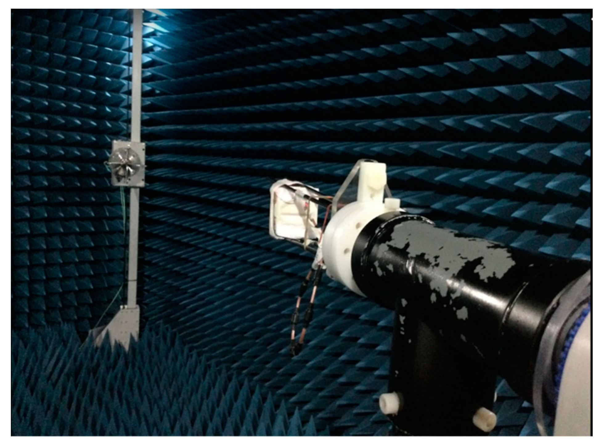
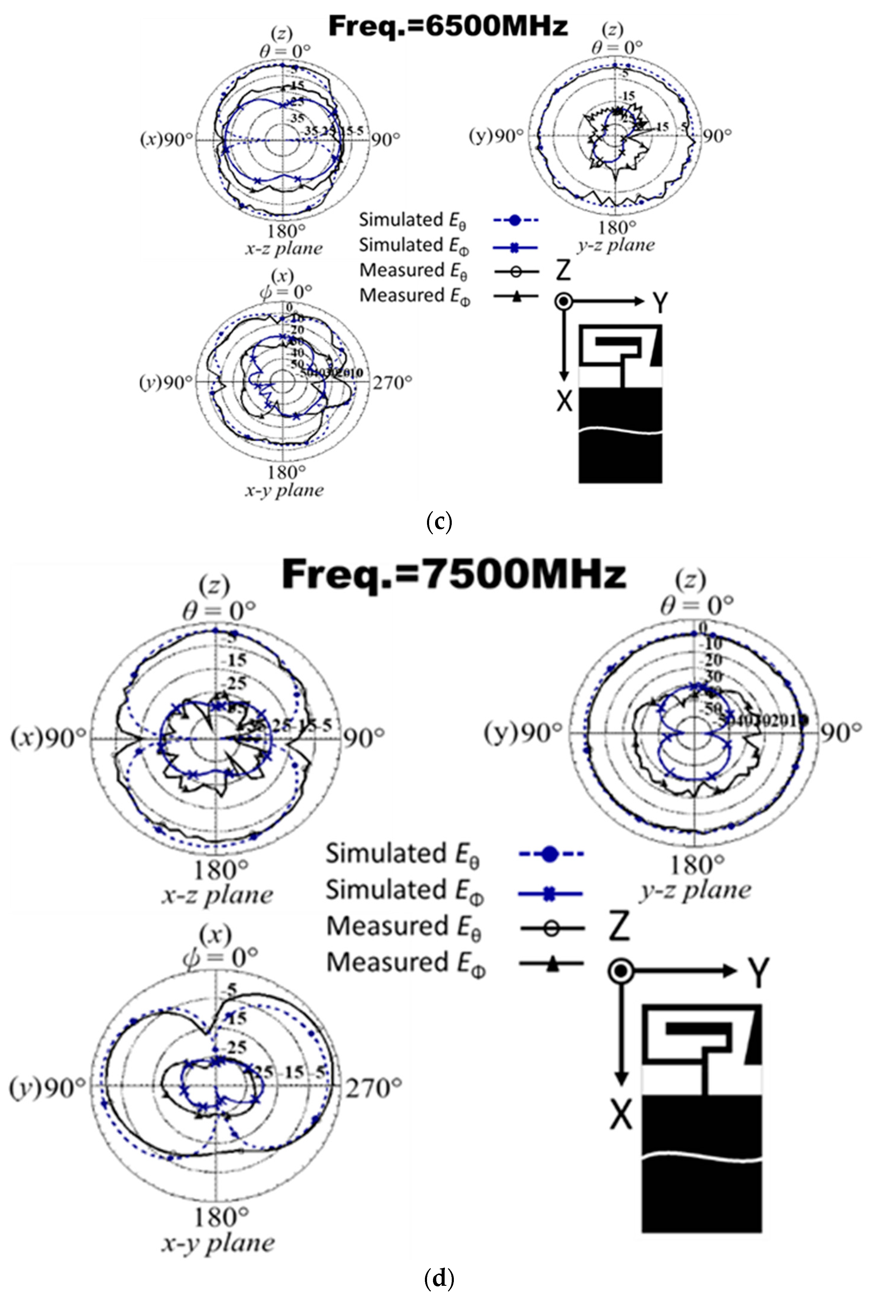
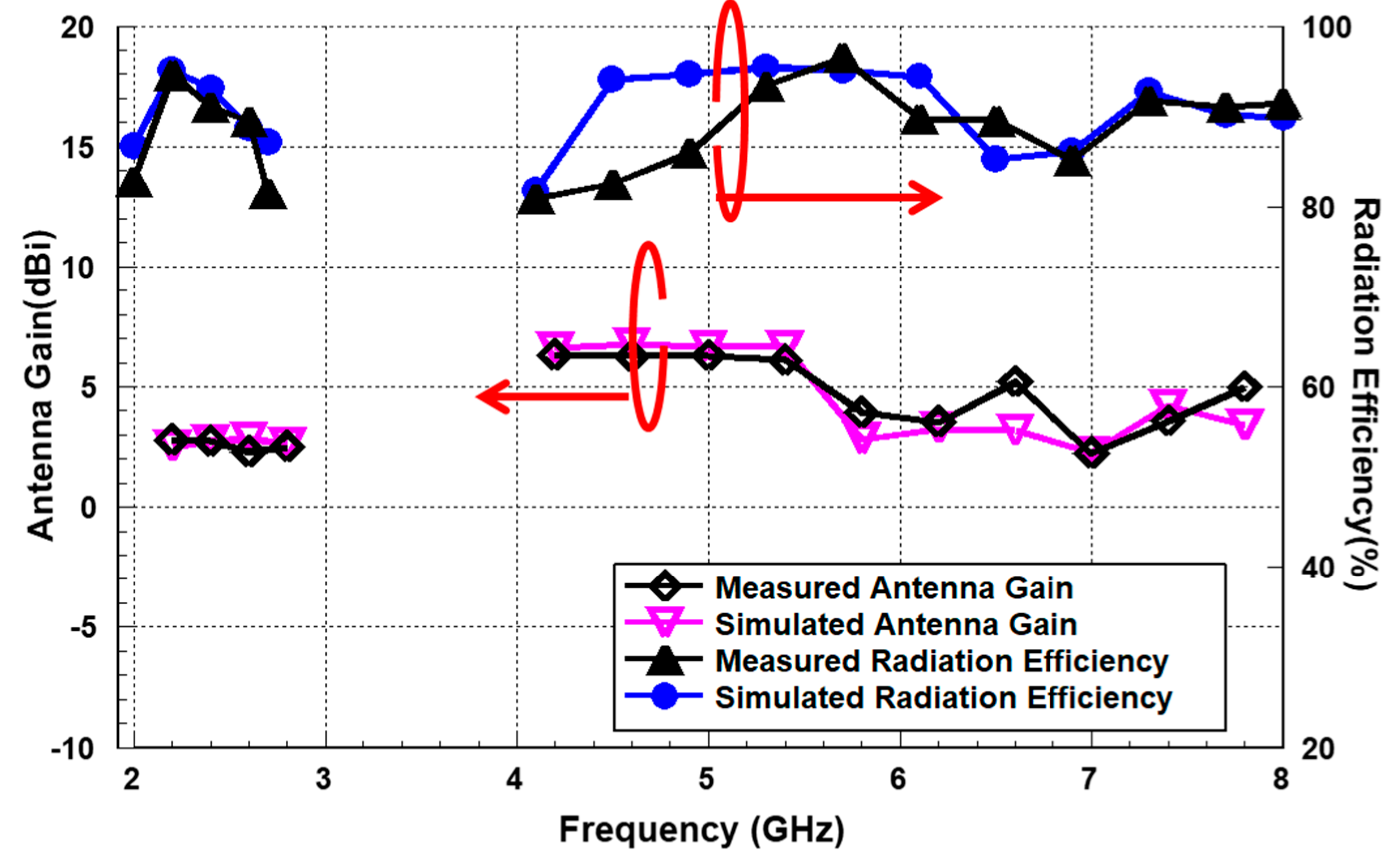
The antenna radiation performance verification uses the AMS-8100 model anechoic chamber antenna measurement system manufactured by ETS-Lindgren, as shown the Figure 5.The simulation and measurement radiation patterns are presented in Figure 6, including four operating bands with 2450, 5500, 6500, and 7500 MHz. The radiation results reach omnidirectional modes are good agreement with simulated and measured. Furthermore, the antenna gains and efficiencies are also shown in Figure 7. The results are demonstrated that both performances achieve very close with simulation and measurement. The gain can obtain about 2.7 dBi in the lower band, and the gain can get about 6.75 dBi in the upper band. Thus, the antenna efficiency can reach 91% for the lower band, and the antenna efficiency can achieve 93% for the upper band. In addition, the proposed antenna was also compared with recent literature and listed the bandwidth and dimensions, as the Table 1 The proposed antenna characteristic is shown as compact and widely operating bands. This table uses the journal papers of the past two years for antenna design comparison. The proposed antenna design has a larger bandwidth than the literature [26,27,28,29,30]. The antenna’s gain also has a comparable measurement result to the literature [26,27,28,29,30]. The antenna size of the proposed antenna is smaller than in the literature [26,27,28,29,30]. The system ground size is smaller than the literature [26,30]. The overall antenna size is smaller than in the literature [26,28,30].
This antenna design is suitable for multi-functional wireless communication system standards, covering eight systems. The first wireless communication standard supported is 5G with 13 bands of n1/n7/n30/n38/n40/n41/n46/n47/n53/n79/n90/n95/n96 in two operating frequencies within 2110–2690 MHz and 5150–7125 MHz. The second wireless communication standard system is Beyond-5G for low earth-orbiting satellite (LEO) application, which is operated in X band spectrum and is designed by the International Telecommunication Union (ITU), which is the operating frequency from space to earth in 7250 to 7750 MHz and from earth to space in 7900 to 8400 MHz. The third is the LTE system with fifteen frequency bands, including the support bands of 7/10/16/23/30/34/38/40/41/46/47/65/67/68 in the operating frequency of 2000–2690 MHz and 5150–5920 MHz. The fourth standard system is V2X, and DSRC for autonomous vehicles application belongs to the IEEE Wireless Access in the Vehicular Environment (WAVE), covering the operating frequency between 5850–5925 MHz. The fifth, sixth, and seventh supported system is ISM band in those operating frequencies including 2450–2483.5 MHz, 2300–2690 MHz, 3400–3590 MHz, 5170–5930 MHz, 5150–5350 MHz, and 5725–5850 MHz to correspond to the wireless communication standard with WiFi 2.4G/5G, WiMAX, and Bluetooth. In addition, the WiFi 6 band also is designed in the operating frequency of 5925–7125 MHz. Finally, Sirius/XM Radio has also supported the 2320–2345 MHz band for the in-vehicle infotainment system (IVI system). The results of the proposed antenna have been analyzed by simulation and measurement. As a result, the proposed antenna has stable radiation and a widely broadband characteristic in this research.

4. Conclusions

Herein, we have presented the proposed antenna structure with two branches that can achieve dual-band and broadband bandwidth characteristics. Moreover, the antenna performances have been analyzed, validated, and manufactured. Thus, this design is suitable for in-vehicle infotainment and autopilot equipment systems in autonomous vehicle communication systems, including 5G, B5G, 4G, V2X, ISM band of WLAN, Bluetooth, WiFi 6 band, WiMAX, and Sirius/XM Radio application.

Author Contributions

Conceptualization, M.-A.C.; methodology, M.-A.C.; software, M.-A.C.; validation, M.-A.C. and C.-W.Y.; formal analysis, M.-A.C.; investigation, M.-A.C.; resources, M.-A.C.; writing—original draft preparation, M.-A.C.; writing—review and editing, M.-A.C.; visualization, M.-A.C.; supervision, M.-A.C.; project administration, M.-A.C.; funding acquisition, M.-A.C. All authors have read and agreed to the published version of the manuscript.

Funding

This work was supported by the Ministry of Science and Technology, Taiwan, R.O.C under Grant Project MOST 109-2222-E-027-008.

Data Availability Statement

All data are included within manuscript.

Conflicts of Interest

The authors declare no conflict of interest.

References

  1. Bassoli, R.; Granelli, F.; Arzo, S.T.; Di Renzo, M. Toward 5G cloud radio access network: An energy and latency perspective. Trans. Emerg. Telecommun. Technol. 2021, 32, e3669. [Google Scholar] [CrossRef]
  2. Zebari, G.M.; Zebari, D.A.; Al-zebari, A. Fundamentals of 5G Cellular Networks: A Review. J. Inf. Technol. Inform. 2021, 1, 1–5. [Google Scholar]
  3. Kao, L.-C.; Liao, W. 5G intelligent A+: A pioneer multi-access edge computing solution for 5G private networks. IEEE Commun. Stand. Mag. 2021, 5, 78–84. [Google Scholar] [CrossRef]
  4. Gao, G.; Li, W. Architecture of visual design creation system based on 5G virtual reality. Int. J. Commun. Syst. 2021, e4750. [Google Scholar]
  5. Alshouiliy, K.; Agrawal, D.P. Confluence of 4g lte, 5g, fog, and cloud computing and understanding security issues. In Fog/Edge Computing For Security, Privacy, and Applications; Springer: Cham, Switzerland, 2021; pp. 3–32. [Google Scholar]
  6. Chan, T.K.; Chin, C.S. Review of autonomous intelligent vehicles for urban driving and parking. Electronics 2021, 10, 1021. [Google Scholar] [CrossRef]
  7. Mahmoud, H.H.H.; Amer, A.A.; Ismail, T. 6G: A comprehensive survey on technologies, applications, challenges, and research problems. Trans. Emerg. Telecommun. Technol. 2021, 32, e4233. [Google Scholar]
  8. Dao, N.-N.; Pham, Q.-V.; Tu, N.H.; Thanh, T.T.; Bao, V.N.Q.; Lakew, D.S.; Cho, S. Survey on aerial radio access networks: Toward a comprehensive 6g access infrastructure. IEEE Commun. Surv. Tutor. 2021, 23, 1193–1225. [Google Scholar] [CrossRef]
  9. Guo, F.; Yu, F.R.; Zhang, H.; Li, X.; Ji, H.; Leung, V.C. Enabling massive IoT toward 6G: A comprehensive survey. IEEE Internet Things J. 2021, 8, 11891–11915. [Google Scholar] [CrossRef]
  10. Kulkarni, J. Wideband cpw-fed oval-shaped monopole antenna for wi-fi5 and wi-fi6 applications. Prog. Electromagn. Res. C 2021, 107, 173–182. [Google Scholar] [CrossRef]
  11. Kulkarni, J.; Sim, C.Y.D. Multiband, miniaturized, maze shaped antenna with an air-gap for wireless applications. Int. J. RF Microw. Comput.-Aided Eng. 2021, 31, e22502. [Google Scholar] [CrossRef]
  12. Xu, H.; Chen, Z.; Zhao, Z.; Liu, H.; Zhu, S. A flexible and compact tri-band antenna for vehicular wireless video transmission systems. Int. J. RF Microw. Comput.-Aided Eng. 2021, 31, e22741. [Google Scholar] [CrossRef]
  13. Wong, K.-L.; Chang, H.-J.; Wang, C.-Y.; Wang, S.-Y. Very-low-profile grounded coplanar waveguide-fed dual-band WLAN slot antenna for on-body antenna application. IEEE Antennas Wirel. Propag. Lett. 2019, 19, 213–217. [Google Scholar] [CrossRef]
  14. Wen, L.; Gao, S.; Yang, Q.; Luo, Q.; Yin, Y.; Ren, X.; Wu, J. A compact monopole antenna with filtering response for WLAN applications. In Proceedings of the 2019 International Symposium on Antennas and Propagation (ISAP), Xi’an, China, 27–30 October 2019; pp. 1–3. [Google Scholar]
  15. Liu, D.Q.; Zhang, M.; Luo, H.J.; Wen, H.L.; Wang, J. Dual-band platform-free PIFA for 5G MIMO application of mobile devices. IEEE Trans. Antennas Propag. 2018, 66, 6328–6333. [Google Scholar] [CrossRef]
  16. Ali, T.; Khaleeq, M.M.; Biradar, R.C. A multi-band reconfigurable slot antenna for wireless applications. AEU-Int. J. Electron. Commun. 2018, 84, 273–280. [Google Scholar] [CrossRef]
  17. Rezapour, M.; Rashed-Mohassel, J.; Keshtkar, A.; Naser-Moghadasi, M. Isolation enhancement of rectangular dielectric resonator antennas using wideband double slit complementary split ring resonators. Int. J. RF Microw. Comput.-Aided Eng. 2019, 29, e21746. [Google Scholar] [CrossRef]
  18. Ng, W.-H.; Lim, E.-H.; Bong, F.-L.; Chung, B.-K. Folded patch antenna with tunable inductive slots and stubs for UHF tag design. IEEE Trans. Antennas Propag. 2018, 66, 2799–2806. [Google Scholar] [CrossRef]
  19. Kulkarni, J. Multi-band printed monopole antenna conforming bandwidth requirement of GSM/WLAN/WiMAX standards. Prog. Electromagn. Res. Lett. 2020, 91, 59–66. [Google Scholar] [CrossRef]
  20. Ghaffar, A.; Li, X.J.; Hussain, N.; Awan, W.A. Flexible frequency and radiation pattern reconfigurable antenna for multi-band applications. In Proceedings of the 2020 4th Australian Microwave Symposium (AMS), Sydney, NSW, Australia, 13–14 February 2020; pp. 1–2. [Google Scholar]
  21. Yang, G.; Zhang, S.; Li, J.; Zhang, Y.; Pedersen, G.F. A multi-band magneto-electric dipole antenna with wide beam-width. IEEE Access 2020, 8, 68820–68827. [Google Scholar] [CrossRef]
  22. Chung, M.A. Embedded 3D multi-band antenna with ETS process technology covering LTE/WCDMA/ISM band operations in a smart wrist wearable wireless mobile communication device design. IET Microw. Antennas Propag. 2020, 14, 93–100. [Google Scholar] [CrossRef]
  23. Camacho-Gomez, C.; Sanchez-Montero, R.; Martinez-Villanueva, D.; Lopez-Espi, P.-L.; Salcedo-Sanz, S. Design of a multi-band microstrip textile patch antenna for LTE and 5G services with the CRO-SL ensemble. Appl. Sci. 2020, 10, 1168. [Google Scholar] [CrossRef] [Green Version]
  24. Kumar, C.M.; Muvvala, N.K. Multi band metamaterial inspired L type slot patch antenna. In Proceedings of the 2020 International Conference on Smart Technologies in Computing, Electrical and Electronics (ICSTCEE), Bengaluru, India, 9–10 October 2020; pp. 34–38. [Google Scholar]
  25. Khan, M.I.; Chandra, A.; Kumar, V.; Das, S. A planar dual band dual polarized slot antenna using coplanar waveguide. In Proceedings of the 2018 IEEE International Students’ Conference on Electrical, Electronics and Computer Science (SCEECS), Bhopal, India, 24–25 February 2018; pp. 1–4. [Google Scholar]
  26. Ghouz, H.H.M.; Sree, M.F.A.; Ibrahim, M.A. Novel wideband microstrip monopole antenna designs for WiFi/LTE/WiMax devices. IEEE Access 2020, 8, 9532–9539. [Google Scholar] [CrossRef]
  27. Le, T.T.; Yun, T.-Y. Miniaturization of a dual-band wearable antenna for WBAN applications. IEEE Antennas Wirel. Propag. Lett. 2020, 19, 1452–1456. [Google Scholar] [CrossRef]
  28. Zhang, H.; Chen, D.; Zhao, C. A novel printed monopole antenna with folded stepped impedance resonator loading. IEEE Access 2020, 8, 146831–146837. [Google Scholar] [CrossRef]
  29. Sreelakshmi, K.; Rao, G.S.; Kumar, M. A compact grounded asymmetric coplanar strip-fed flexible multi-band reconfigurable antenna for wireless applications. IEEE Access 2020, 8, 194497–194507. [Google Scholar] [CrossRef]
  30. Kulkarni, J. Multiband triple folding monopole antenna for wireless applications in the laptop computers. Int. J. Commun. Syst. 2021, 34, e4776. [Google Scholar] [CrossRef]
Figure 1. Disclosure of recommended antenna structure: (a) view of the antenna structure and overall design of the measurement layout, (b) schematic diagram of the layout applied to IoT devices; (c) detailed dimensions and layout of the antenna; (d) antenna entity diagram; (e) the clockwise spiral shape of two branches (Strip 1 and Strip 2).
Electronics 10 02715 g001
Figure 2. Surface current distribution analysis at: (a) 2350 MHz; (b) 2450 MHz; (c) 5080 MHz; (d) 5500 MHz; (e) 5890 MHz; (f) 6500 MHz; (g) 7150 MHz.
Electronics 10 02715 g002aElectronics 10 02715 g002b
Figure 3. The verification result of the reflection coefficient with simulation and measurement for the proposed monopole antenna.
Electronics 10 02715 g003
Figure 4. The evolution analysis with various types and lengths for the proposed antenna: (a) evolution analysis of antenna design with type 1, 2, and 3; (b) strip length W9.
Electronics 10 02715 g004
Figure 5. Photographs of the fabricated antenna PCB and the process of measurement.
Electronics 10 02715 g005
Figure 6. Simulation and measurement of radiation patterns at different operating frequencies: (a) 2450 MHz; (b) 5500 MHz; (c) 6500 MHz; (d) 7500 MHz.
Electronics 10 02715 g006aElectronics 10 02715 g006b
Figure 7. The results of peak gain and radiation efficiency.
Electronics 10 02715 g007
Table 1. Comparison of the proposed antenna with other research literature.
ReferencesPublication YearOverall Size (mm2)System Ground Size (mm2)Antenna Size (mm2)Operation Range (GHz)Resonant Frequency (GHz)Bandwidth (%)Gain (dBi)Applications
[26]202036 × 3836 × 21.738 × 24.44.5–5.575.03530%6WiFi/LTE/WiMax
(1070 MHz)
[27]202020 × 1910 × 1913.5 × 102.4–2.542.745.1% (140 MHz)
3.7% (220 MHz)
2.1 WBAN
5.72–5.945.833.5
[28]202054 × 375 × 5454 × 321.6–2.21.931.5% (600 MHz)1.67-
[29]202024 × 198 × 8.516 × 162.33–2.472.45.8% (140 MHz)
13.3% (240 MHz)
6.6% (370 MHz)
2.26Bluetooth/5G NR/WLAN
3.68–3.926.33.14
5.38–5.755.5653.73
[30]2021260 × 208260 × 20021 × 82.25–2.642.4455.8% (390 MHz)
13.3% (380 MHz)
6.6% (1410 MHz)
4.38LTE/WIFI/sub-6 GHz/5G bands
3.25–3.633.444
5–6.415.7055.68
Proposed-50 × 1042.5 × 1012.5 × 7.52–2.742.4631.22% (740 MHz)
65.29% (3938 MHz)
2.75G, B5G, 4G, V2X, ISM band of WLAN, Bluetooth, WiFi 6 band and WiMAX, Sirius/XM Radio
4.062–86.2056.75
Publisher’s Note: MDPI stays neutral with regard to jurisdictional claims in published maps and institutional affiliations.