Article

Connected Objects Geo-Localization Based on SS-RSRP of 5G Networks

1
Innov’Com Laboratory, Higher School of Communications of Tunis, Sup’Com, University of Carthage, Cité Technologique des Communications Route de Raoued Km 3.5, El Ghazala Ariana Tunisie 2083, Tunisia
2
Computer Science Department, King Abdulaziz University, Jeddah 21589, Saudi Arabia
*
Author to whom correspondence should be addressed.
Electronics 2021, 10(22), 2750; https://doi.org/10.3390/electronics10222750
Submission received: 15 September 2021 / Revised: 5 November 2021 / Accepted: 8 November 2021 / Published: 11 November 2021
(This article belongs to the Special Issue Future Generation Wireless Communication)

Abstract

:
The Global Positioning System (GPS) is not the only way to solve connected objects’ geo-localization problems; it is also possible to use the mobile network infrastructure to geo-locate objects connected to the network, using antennas and signals designed for voice and data transfer, such as the 5th generation network. 5G is considered as a least expensive solution because there is no specific equipment to set up. As long as the object is in an area covered by the network, it connects to the nearest 5G Micro-Cell (MC). Through exchange of signals with the MC node we can locate the object. Currently, this location is very fast with less than 5 s but not very precise because it depends on the number of MC antennas of the operator in question and their distance. This paper presents a novel technique to geo-locate connected object in a covered 5G area. We exploit the 5G SS-RSRP used for signal quality measurement, to estimate the distance between two Connected Objects (COs) in move and in a dense urban area. The overall goal is to present a new concept laying on the 5G SS-RSRP signalling. The proposed solution takes into consideration the Deterministic and the Stochastic effect of the received signals which is not treated by the previous works. The accuracy is optimum even after approaching to the distance of one meter which is not reached in previous works too. Our method can also be deployed in the upcoming 5G network since it relies on 5G signals itself. This work and that of Wang are both based on RSRP and give comparable theoretical complexities therefore comparable theoretical execution times as well. However, to obtain a reliable learning Wang requires a huge amount of data which makes it difficult to get a real time aspect of this algorithm. The use of RSRP and the elimination of the learning phase will give more chance to our work to achieve desired performances. Numerical results show the appropriateness of the proposed algorithms and good location accuracy of around one meter. The Cramer Rao Lower Bound derivations shows the robustness of the proposed estimator and consolidate the work.

1. Introduction

Global Positioning System (GPS) has for decades been the unique practical way of global positioning. This long period of pioneering work has allowed GPS to acquire major technical improvements in terms of equipment and theory. But the most important benefit of GPS remains linked to the change of human habits by making localization an unavoidable feature in our lives and in different fields such as transports, military, health and games. In spite of this remarkable accomplishment, GPS still has limitations that slow down and keep on slowing down progress in the field of localization. These limitations are mainly related to the accuracy of the satellite signals used or their availability.
Indeed, for security reasons, GPS limits the accuracy of signals used in the civil domains giving a geo-localization of the order of a few meters. The security and the strategic nature of this limitation confirms that this will not be lifted in the coming years.
Location-based applications such as vehicle collision detection, real-time Assisted Living for healthcare providers or visually impaired people localization will continue to be subject of scientific papers until we have improved the accuracy to a few centimeters. However, the next generation of mobile network, 5G, promises a leap in performance technologically compared to 4G. They can offer a flow rate of 10 times higher than the current 4G. The latency is also reduced tremendously since it is divided by 10 compared to 4G and LTE-A. The 5G network ensures robust reliability and radio link availability. The network is also able to simultaneously connect a large number of objects with a better energy efficiency [1]. All those criteria make the 5G a strong candidate to assist GPS features.
Localization solutions based on radio signals have evolved theoretically and fundamentally over the last few decades for the 4G and older generations. Works in 2G and 3G such as [2,3,4] have accuracy over 100 m. Ref. [5] use trilateration techniques in 3G and 4G networks and have achieved accuracies of 50 m. Refs. [6,7] use delay techniques and obtain accuracies of 10 m.
However, the next generation of mobile network, 5G, promises a leap in technology performance compared to 4G and previous generations. They can offer a flow rate of 10 times higher than the current 4G. The latency is also reduced tremendously since it is divided by 10 compared to 4G and LTE-A. The 5G network ensure robust reliability and radio link availability. The network is also capable to simultaneously connect a large number of objects with a better energy efficiency. All those criteria make the 5G a strong candidate to assist GPS features.
The performance promised by the arrival of 5G is estimated in the latest 3GPP standard update to be less than 4 m. This will unlock new opportunities for location-based applications such as vehicle collision detection or precise topographic mapping. Recent research works are trying to improve the accuracy to reach the 3GPP objectives and specially to satisfy the requirements of new applications [8].
The works in [9,10,11] use mmWave and a massive number of antennas, confirming achievable positioning accuracy below one meter. In [12] authors use RSS measurements and distributed massive MIMO and show an accuracy of 35 m from a single base station. The works in [13,14,15] use multipath assisted techniques with advanced tracking algorithms for positioning. Other works such as [16,17,18,19] propose collaborative positioning solutions and localization solutions in ultra-dense networks where the simulation of certain works shows the ability to reach accuracies of less than one meter.
Khan et al. [20] provided an algorithm to predict the location of a person in 5G networks using RSS measurements. For this purpose, the authors use in the first step the relative coordinates by using Isomap and in a second step these coordinates are transformed by a Procrustes analysis. The performance of their algorithm is evaluated using the Cramer-Rao lower bound. Talvitie et al. [21] address high-speed object positioning and tracking in a 5G network. The authors obtain a positioning accuracy of less than 3 m for real data collected on a high-speed train route between Shanghai and Beijing. Authors use an extended Kalman filter to predict the positions.
The objective of this paper is to present an innovative method to exploit the 5G radio network to assist GPS in Geo-localization. The evaluation was carried out on a simulated signal on air and compared to recently published works. Parameters, such as Synchronization Signal-Reference Signal Received Power (SS-RSRP), distance between two COs were estimated. The method was validated together with the suitable distribution law to inform about the accuracy of the precision. In fact, distance is the only exact metric that we can use as a basis for experimental validation of our method. Whether it is the distance between two COs or the distance between two positions of a single COs, this measurement can be obtained easily and with the desired level of accuracy. Knowing D i j this will be a key solution to many problems in industry 4.0, e.g., (inter-car distance detection, inter-robot distance detection and even inter-drone etc....). The distance D i j will become fully known without the deployment of any sensors or GPS equipment. In 5G concept any single device will be covered immediately by the nearest 5G antenna (MC). Hence the coverage is guaranteed everywhere, certainly in outdoors or even in indoors. Another important application, knowing D i j , will give full knowledge of a realtime constellation of Connected Objects (COs) in move. In this work, following are the four global achievements:
  • We demonstrated analytically and by simulation that the proposed algorithm gives good accuracy when approaching the 0.55 m barrier. This barrier has never been reached in previous works.
  • We have full knowledge of the error distribution, as it follows the Rayleigh law. This knowledge will help to tune the solution to other positioning scenarios and applications.
  • The CRLB is derived to showcase the robustness of the proposed estimator at low and high SNR. Theoretical analysis and simulation both confirm the validity of the proposed model.
  • A comparative study of complexity is also performed with two recent works Wang in [22] and Kim in [23].

2. System Model

2.1. Path Loss Model

In urban dense environment, the propagated radio signals are subject to many electromagnetic phenomena such as, reflection, refraction, scattering and diffraction. Hence the received signal will be guided through multiple paths, and this will create the multi-paths fading subject to destructive or constructive interference. In large scale fading cases, obstacles trigger shadowing effects and create multi-paths and in small scale fading interference will occur and create multi-paths as well.
The behavior of the Radio Signal Strength (RSS) in time and in space, is two folds: deterministic and stochastic process. The degradation of power signal strength is defined as Path Loss P L . Many factors could be used for the estimation of P L , such as multi-paths phenomenon, distance from transmitter, penetration losses through walls, etc. The RSS expression is the combination of deterministic effects and stochastic effects using Gaussian model as
P L d = P L d 0 + 10 n log 10 ( d d 0 ) Deterministic effect + χ σ Stochastic effect [ dBm ]
where d represents the l 2 -norm distance between the transmitter at ( x t , y t ) and the receiver ( x r , y r ) . P L d 0 is the loss at a reference distance d 0 . The constant n is generally greater than 2 and specific to propagation environment. χ σ is the main stochastic behavior of P L and it could be modeled as zero mean Gaussian random variable with variance σ 2 . However, when the channel is time variant the wide-sense stationary process assumption is lost and the shadowing or the multi-paths fading effects will dominate χ σ  [24].
The RSS could be modeled as described by the equation below:
RSS ( d , t ) = RSS d 0 10 n log 10 ( d d 0 ) Path loss Φ dBm ( d ) Shadowing Ξ dBm ( d , t ) Multipath
From (2) the path loss is considered as large scale fading (very slow process) and the remaining part is considered as small scale fading (fast process) due to multi-paths and shadowing. The main part responsible for shadowing effects is Φ dBm = log 10 ( Φ mW ) and Φ N ( 0 , σ Φ 2 ) is a zero mean Gaussian distribution with variance σ Φ 2 . Next to shadowing, multi-paths fading could be also modeled in function of space and time as Ξ dBm ( d , t ) = 10 log 10 ( Ξ mW ) and Ξ dBm ( d , t ) N ( 0 , σ Ξ 2 ) . In many commercial wireless devices the path loss (RSS) can be recoded using the Received Signal Strength Indicator (RSSI) metric. For the rest of this paper, the RSS will be used as RSSI recoded values from wireless devices.

2.2. SS-RSRP Model

Synchronization Signal-Reference Signal Received Power (SS-RSRP) is useful for 5G system analysis. It can also shed light on emerging 5G Public Networks (PN) operation and thus help develop local licensing regulations and interference control mechanisms. Generally SS-RSRP is measured through the use of pilots symbols, specific to the deployed cell commonly known as Cell specific Reference Signal (CRS) in 4G networks and altered in 5G by the Synchronization Signal Block (SSB). The accurate measurement of SS-RSRP mainly in micro cells and dense urban area and where interferences become a potential source of signal degradation, makes the accuracy of received SS-RSRP a challenging task. Henceforth, this subsection, will derive analytically the received SS-RSRP based on the full knowledge of RSS signal.
Another approximation of P L is used in literature as P L = P E P c a + G R x , where P E is the transmission power of T x antenna, P c a is the cable losses and G R x is the R x antenna gain.
The proposed model will be elaborated based on Figure 1, along with the following assumptions:
1
We will assume in this paper, that there is no cable losses to simplify the calculation process. Hence P L = P E + G R x .
2
The antenna gain depends on the direction of arrival to the Macro-Cell (MC) G R x = 10 ( 180 θ 70 π ) 2  [25].
Currently OFDM is the potential waveform for 5G networks, hence we consider the k t h -OFDM symbol in baseband model. The transmitter and receiver are both equipped with one antenna ( n r = n t ) . The channel type deployed in this paper is a selective Rayleigh channel.
The analytical function of the received k t h -OFDM symbol is expressed as y k = l = 0 L 1 h k ( l ) u k ( k l ) + w k , where u k is the transmitted symbol, w k is zero mean white Gaussian complex noise of variance N 0 2 and L is the number of multipath. Let us define the equivalent channel matrix C ( n c + n g ) × ( n c + n g ) , where n c is the number of subcarrier and n g is the number of subcarrier reserved for the Cycle Prefix (CP) interval. Thus one can rewrite the k t h -OFDM received signal in matrix notation as y k = G k u k + w k , where y k C ( n c + n g ) × 1 and w k C ( n c + n g ) × 1 represents additive white Gaussian noise channel at time k. When removing CP, the frequency domain signal is generated again by a DFT process and the whole mathematical expression is defined as z k = 1 n c ( F I n c ) ξ 2 y k , ξ 2 C n c × ( n c n g + 1 ) is the cycle prefix removing matrix for the first n g elements of y k . This will lead to another expression of the DFT-output as z k = ( F I n t ) ξ 3 ( F 1 I n t ) x k + w k = H k x k + w k , ξ 2 = [ 0 n c n g I n g ] I n g . The matrix ξ 3 C n c × n c is the circulant matrix, and ξ 3 = ξ 2 G k ξ 1 where w k is the noise in the frequency domain with zero mean and variance σ w 2 and H k is C n c × n c frequency domain matrix defined as H k = ( F I n c ) ξ 3 ( F 1 I n c ) .
Now we can express analytically the channel matrix in frequency domain H k as [26,27]:
H k = H k ( 0 ) 0 0 H k ( n c n t )
where nth block H k ( n ) represents the OFDM channel gain at the nth subcarrier and can be written as
H k ( n ) = l = 0 L 1 h k ( l ) exp j 2 π n k n c
The received frequency-domain signal z n , k at the DFT output can be expressed as
z n , k = H ( n ) x n , k + w n , k
In 5G NR the Synchronization Signal Block SSB is used for signal measurement, therefore N special sub-carriers dedicated to SSB measurement are deployed. The SS-RSRP signal is defined as average of channel power during one measurement period of (SSB). Hence
SS RSRP = 1 N k = 0 N 1 H k 2 n c L P h 2 N
The frequency domain channel H n , k is a diagonal, with the following expression
H k 2 = H k ( 0 ) 2 0 0 H k ( n c ) 2 = H k H k H = n c H ( n ) 2 1 n n c
whereas
H k ( n ) 2 = l = 0 L 1 h k ( l ) exp j 2 π n k n c 2
l = 0 L 1 h k ( l ) exp j 2 π n k n c 2
l = 0 L 1 h k ( l ) 2 = L . P h 2
where P h = E { h k p ( l ) h k k m ( l ) * } denotes the mean power to each channel coefficient in time domain. On the other side, the mathematical expression of RSSI at the receiver could be interpreted as:
RSSI = n = 1 N ( H k ( n ) ) 2 L P h 2
Henceforth, the SS-RSRP in dBm could be re-written as
SS RSRP [ dBm ] = RSSI [ dBm ] + 10 log 10 ( n c ) 10 log ( N )
Whereas the RSSI values are fully known at the receiver side, hence we can estimate the SS-RSRP values as follows:
SS RSRP ^ [ dBm ] = RSSI [ dBm ] + 10 log 10 ( n c N )
= P E [ dBm ] + G R x [ dBm ]
When combining (2) and (12), we can derive the expression of the angle θ i ^ and the frontal distance with the MC as
θ i ^ = ( 70 π 180 ) 2 ( SS RSRP i ^ P E )
d i ^ = d 0 10 RSSI i ^ RSSd 0 + Φ i + Ξ i 10 n
Finally, when we refer to Figure 1 the distance between two COs in 5G cell will be estimated as
D i j = d i 2 + d j 2 2 d i d j cos ( α ) = α i j

3. Distance Estimation

The initial phase of the proposed solution is to simulate a realistic RSS environment using Matlab. The model setup deploys the log-normal shadowing model as presented in (2). All parameters are set using empirical observations and Gaussian noises Φ d B m ( d ) and Ξ d B m ( d , t ) . The MC position is supposed well known fixed at (0,0) and any estimated distance will be calculated based on ( l 2 ) norm. Each environment has its own empirical path loss constants n as in (2). Hence it will be crucial to extrapolate correct n values as described. The n value is obtained by setting the derivative of the following mean square error estimate J ( n ) = Σ i = 1 k ( P L d 0 χ σ 10 n log 10 ( d i d 0 ) ) 2 to zero, J ( n ) n = 0 . The Algorithm 1 describes the initial phase for a realistic RSS environment, measured at the receive antenna, where P t denotes the transmit power (dBm) of the transmitter, d 0 is the reference distance d 0 ( m ) , P d 0 is the received power at the distance d 0 and P L d 0 = P t P d 0 is the path loss at the reference distance. The Algorithm 1 will serve to generate a realistic RSS value to be used in the next estimation phase as described in Algorithm 2. The Algorithm 2 summarizes the needed steps to estimate the distance between two COs. The COs are supposed to be in move while deploying a 5G NR radio access network.
Algorithm 1 Simulation of a realistic RSS environment
1:
Phase I: Initialization
2:
CO position = ( x 1 , y 1 )                    ▹ Initial position of the first CO
3:
MC position = ( 0 , 0 )                      ▹ Initial position of the MC
4:
Estimate n value using J ( n ) n = 0
5:
Set values of P t , d 0 , P d 0 , P L d 0
6:
Φ dBm ( d ) = r a n d ( x , y )        ▹ Std. deviation of Shadowing in spatial domain (x,y)
7:
Ξ dBm ( d , t ) = r a n d ( 2 )        ▹ Std. deviation of Gaussian noise in temporal domain
8:
Phase II: Generates a real RSS value
9:
forx in 0 to l i m i t 1  do
10:
    for y in 1 to l i m i t 2  do
11:
        if  ( x , y ) == ( 0 , 0 )  then
12:
           rss ( i , j ) = 0
13:
        else if  ( x , y ) == ( x 1 , y 1 ) then
14:
           rss ( x , y ) = P t
15:
        else
16:
           rss ( x , y ) = P t P L d 0 10 n log 10 ( ( x 1 2 + y 1 2 ) d 0 ) Φ dBm ( d ) Ξ dBm ( d , t )
17:
        end if
18:
    end for
19:
end for
Algorithm 2 Distance Estimation in 5G NR
1:
fori in 1 to q do
2:
     RSSI i values acquisition using Algorithm 1
3:
     SS RSRP i ^ [ dBm ] = RSSI i [ dBm ] + 10 log 10 ( n c N )         ▹ SS-RSRP Estimation as in (12)
4:
     θ i ^ = ( 70 π 180 ) 2 ( SS RSRP i ^ P E i )                  ▹ Angle estimation as in (14)
5:
     d i ^ = d 0 10 RSSI i ^ RSSd 0 + Φ i + Ξ i 10 n                ▹ Frontal distance estimation as in (14)
6:
end for
7:
forj in 1 to p do
8:
     SS RSRP j ^ [ dBm ] = RSSI j [ dBm ] + 10 log 10 ( n c N )         ▹ SS-RSRP Estimation as in (12)
9:
     θ j ^ = ( 70 π 180 ) 2 ( SS RSRP j ^ P E j )                 ▹ Angle estimation as in (14)
10:
     d j ^ = d 0 10 RSSI j ^ RSSd 0 + Φ j + Ξ j 10 n                ▹ Frontal distance estimation as in (14)
11:
end for
12:
fori in 1 to q do
13:
    for j in 1 to p do
14:
         D i j = d i 2 + d j 2 2 d i d j cos ( α i j )           ▹ Mutual distance estimation as in (16)
15:
    end for
16:
end for

4. Numerical Results and Validation

We consider a 5G NR transmission system whose parameters, taken by 5G Release 15 [28], are listed in Table 1. To obtain all the numerical results shown in the next of this section, 10,000 independent realizations were simulated. Perfect knowledge of channel state has been supposed in all our performance evaluation trials.

4.1. MSE Method

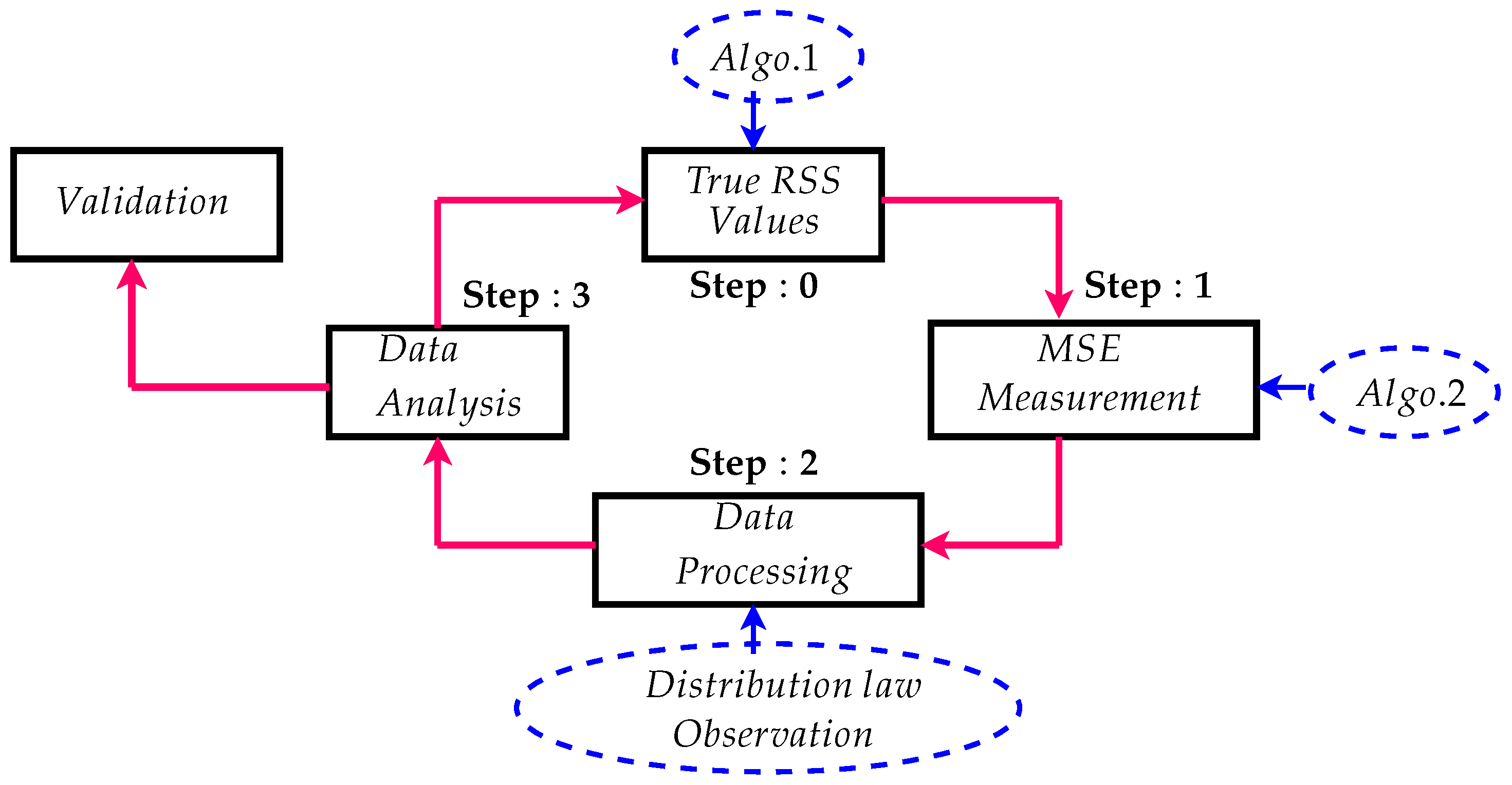
We used Matlab software Release 2019 Ubuntu version to compile Algorithms 1 and 2. Initially a realistic radio signal strength environment is generated using Algorithm 1. The two COs are supposed to be mobile within one meter square with a full coverage ensured by an MC. Afterward Algorithm 2 is enabled to generate the estimated distance between the two COs. We illustrated the whole process as in Figure 2.
In order to scale the accuracy of the proposed Algorithm, we used the Minimum Mean Square Error (MSE). As it is illustrated in Figure 3 the MSE tends to zeros at the very first rounds of Algorithm 2. We notice that the convergence time for Algorithm 2 is not immediate, this is due to the needed calculation time required for RSSI generation in Algorithm 1 and also the processing time needed for Algorithm 2. Henceforth the MSE values become zeros after a short transitional phase.

4.2. Accuracy Quantification

We can quantify the accuracy of our method as the deviation in horizontal and vertical coordinates ( x , y ) compared to the estimated coordinates ( x ˜ , y ˜ ) . Q = ( x x ˜ , y y ˜ ) = ( X , Y ) . Normal distribution appears to be the most convenient choice, especially in the light of Figure 4. One can consider the deviations at x and y are independent random variables and follow Gaussian laws of zero mean and variance σ 2 = 0.1758 m. The intervals next to the parameter are the 95% confidence intervals for the distribution parameters. These values are collected after Matlab processing of Figure 4. The density of joint probability of deviations ( X , Y ) is given by:
P X Y ( x , y ) = P X ( x ) P Y ( y ) = exp ( x 2 + y 2 2 σ 2 ) 2 π σ 2
The characterization of the precision in x and in y does not give information about the probability of the distance between the desired point and the point obtained. To obtain this probability, we change Cartesian coordinates to polar coordinates according to the transformation:
( X , Y ) = ( R cos ( Θ ) , R sin ( Θ ) )
Thus the Jacobian of transformation is r :
r = ( x , y ) ( r , θ ) = cos ( θ ) sin ( θ ) r sin ( θ ) r cos ( θ )
This will lead to:
P R Θ ( r , θ ) = r 2 π σ 2 exp ( r cos ( θ ) ) 2 + ( r sin ( θ ) ) 2 2 σ 2
= r 2 π σ 2 exp ( r 2 2 σ 2 )
Hence to find the marginal, it is necessary to integrate on the other random variable, that is:
P Θ ( θ ) = r = 0 + P R , Θ ( r , θ )
= r = 0 + r 2 π σ 2 exp ( r 2 2 σ 2 ) d r
= 1 2 π
The angle is therefore uniformly distributed over [0, 2 π ]. On the other hand, we deduce:
P R ( r ) = r σ 2 exp ( r 2 2 σ 2 ) d r
The probability density followed by the distance R is that of a Rayleigh variable as illustrated in Figure 5.
As it is shown in Figure 5, the precision of the proposed method is robust when we are approaching the barrier of one meter. The precision becomes weak while approaching the origin. At distance greater than 0.55 m the error probability tends to the zero.

4.3. Complexity and Performance Analysis

Our solution uses 2 algorithms. The theoretical complexity depends only on the second one since the first one is executed off-line and the complexity of our solution will be O ( n 2 ) . The Algorithm described in [22] is based on SS-RSRP measurements and a step using Random forest classifier with the machine learning Library Sklearn. We are interested here in the Algorithm without considering the learning part which is also executed off-line. The theoretical complexity of this Algorithm is O ( n 2 ) , Kim et al. in [23] proposed a multiple-model PHD filter and map fusion for cooperative positioning and mapping in vehicular networks with 5G mmWave communication links. The proposed framework is based on 3 algorithms. The Map correction Algorithm uses repetitively and successively the two other algorithms. The theoretical complexity of these algorithms is O ( n 3 ) . Presented works in Table 2 are all compliant with 5G standards but with different complexities. The theoretical complexity of Kim et al. is higher than the other two algorithms and therefore the theoretical execution time is higher. Our work and that of Wang are both based on SS-RSRP and give comparable theoretical complexities therefore comparable theoretical execution times. However, to obtain a reliable learning Wang’s method requires a huge amount of data which makes it difficult to be used in real time. The use of the SS-RSRP and the absence of a learning phase are the main advantages of our work that allowed us to achieve the desired performance.

4.4. CRLB Analysis

The Cramer-Rao Bound (CRB) is a second performance criterion that gives a lower bound to the mean square error of estimation in the set of unbiased estimates. It is used here as a performance measure for the proposed estimator. The observed signal is described by (16). It can be written as
D P s i = d i 2 + d j 2 2 d i d j cos ( θ i θ j ) D i j + w ( n )
where w ( n ) is a white Gaussian noise following N ( 0 , σ 2 ) . σ 2 denotes the variance of the white Gaussian noise. In this equation we have four unknown variables Ψ = [ d i , d j , θ i , θ j ] . To derive the CRLB, first, we write the likelihood function as
p ( D i j ; D P s i ) = n = 0 N 1 1 2 π σ 2 exp ( D i j D P s i ) 2 2 σ 2
Since we have
2 p ( D i j ; D P s i ) 2 D P s i = I ( Ψ ) g ( D i j ) D P s i
The Fisher Information matrix I ( Ψ ) doses exist and the CRLB = 1 I ( Ψ ) . In fact
I ( Ψ ) i j = 1 σ 2 n = 0 N 1 Ψ i Ψ j D P s i
After some mathematical manipulations we find
I ( Ψ ) 1 σ 2 2 N σ 2 2 N 0 0
We assume that the sum of sines or cosines becomes negligible for large N.
The CRLB gives the lowest variance of our proposed estimator D i j . Figure 6 shows that the proposed estimator follows at all SNR ranges the CRLB with almost the same gap. At one meter we notice a gap of 9 dB, this is due to the mathematical approximation done to derive the CRLB. When the SNR values increase asymptotically the variance of the estimator becomes closer to the CRLB limit.

5. Conclusions

In this paper we proposed an innovative method to estimate the distance between two mobile COs from the measurements of SS-RSRP when 5G is deployed. We have provided a sophisticated analysis, naturally assuming that the SS-RSRP values depend on the distance from the COs to the MC. In particular, it has been shown that the use of these 5G signals makes it possible to provide good location accuracy without resorting to the GPS system. Using simulations and a detailed analytical study, it has been shown that the proposed algorithms have achieve good location accuracy of distance of around one meter.

Author Contributions

Funding acquisition was ensured by F.A. All the scientific investigation are equally ensured by the three authors: A.B., A.H. and F.A. All authors have read and agreed to the published version of the manuscript.

Funding

This project was funded by the Deanship of Scientific Research (DSR) at King Abdulaziz University, Jeddah, under grant no.(G: 840-611-1441). The authors, therefore, acknowledge with thanks DSR for technical and financial support. The APC was funded by Deanship of Scientific Research (DSR) at King Abdulaziz University.

Institutional Review Board Statement

Not applicable.

Informed Consent Statement

Not applicable.

Data Availability Statement

The study did not report any data.

Conflicts of Interest

The authors declare no conflict of interest.

References

  1. Henk, W.; Gonzalo, S.G.; Giuseppe, D.; Davide, D.; Fredrik, T. 5G mmWave Positioning for Vehicular Networks. IEEE Wirel. Commun. 2017, 24, 80–86. [Google Scholar]
  2. Spirito, M.; Poykko, S.; Knuuttila, O. Experimental Performance of Methods to Estimate the Location of Legacy Handsets in GSM. In Proceedings of the IEEE 54th Vehicular Technology Conference. VTC Fall 2001. Proceedings (Cat. No.01CH37211), Atlantic City, NJ, USA, 7–11 October 2001; Volume 4, pp. 2716–2720. [Google Scholar] [CrossRef]
  3. Borkowski, J.; Niemela, J.; Lempiainen, J. Enhanced Performance of Cell ID+RTT by Implementing Forced Soft Handover Algorithm. In Proceedings of the IEEE 60th Vehicular Technology Conference, 2004. VTC2004-Fall. 2004, Los Angeles, CA, USA, 26–29 September 2004; Volume 5, pp. 3545–3549. [Google Scholar] [CrossRef]
  4. Wennervirta, J.; Wigren, T. RTT Positioning Field Performance. IEEE Trans. Veh. Technol. 2010, 59, 3656–3661. [Google Scholar] [CrossRef]
  5. Sadowski, J. TDOA navigation Using CDMA2000 Signals “Experimental results”. In Proceedings of the 2014 Ubiquitous Positioning Indoor Navigation and Location Based Service (UPINLBS), Corpus Christi, TX, USA, 20–21 November 2014; pp. 265–271. [Google Scholar] [CrossRef]
  6. Duffett-Smith, P.J.; Tarlow, B. E-GPS: Indoor Mobile Phone Positioning on GSM and W-CDMA. In Proceedings of the 18th International Technical Meeting of the Satellite Division of The Institute of Navigation (ION GNSS 2005), Long Beach, CA, USA, 13–16 September 2005; pp. 2762–2768. [Google Scholar]
  7. Gioia, C.; Borio, D. Stand-alone and Hybrid Positioning Using Asynchronous Pseudolites. Sensors 2015, 15, 166–193. [Google Scholar] [CrossRef] [PubMed] [Green Version]
  8. Bartoletti, S.; Conti, A.; Dardari, D.; Giorgetti, A. 5G Localization And Context-Awareness; University of Bologna: Bologna, Italy, 2018. [Google Scholar]
  9. Guerra, A.; Guidi, F.; Dardari, D. Position and Orientation Error Bound For Wideband Massive Antenna Arrays. In Proceedings of the 2015 IEEE International Conference on Communication Workshop (ICCW), London, UK, 8–12 June 2015; pp. 853–858. [Google Scholar]
  10. Wen, F.; Wymeersch, H.; Peng, B.; Tay, W.P.; So, H.C.; Yang, D. A Survey On 5G Massive MIMO Localization. Digit. Signal Process. 2019, 94, 21–28. [Google Scholar] [CrossRef] [Green Version]
  11. Shahmansoori, A.; Garcia, G.E.; Destino, G.; Seco-Granados, G.; Wymeersch, H. 5G Position And Orientation Estimation Through Millimeter Wave MIMO. In Proceedings of the 2015 IEEE Globecom Workshops (GC Wkshps), San Diego, CA, USA, 6–10 December 2015; pp. 1–6. [Google Scholar]
  12. Savic, V.; Larsson, E.G. Fingerprinting-based Positioning in Distributed Massive MIMO Systems. In Proceedings of the 2015 IEEE 82nd Vehicular Technology Conference (VTC2015-Fall), Boston, MA, USA, 6–9 September 2015; pp. 1–5. [Google Scholar]
  13. Wang, W.; Jost, T.; Gentner, C.; Zhang, S.; Dammann, A. A Semiblind Tracking Algorithm For Joint Communication and Ranging with OFDM Signals. IEEE Trans. Veh. Technol. 2015, 65, 5237–5250. [Google Scholar] [CrossRef]
  14. Witrisal, K.; Hinteregger, S.; Kulmer, J.; Leitinger, E.; Meissner, P. High-Accuracy Positioning for Indoor Applications: RFID, UWB, 5G, and Beyond. In Proceedings of the 2016 IEEE International Conference on RFID (RFID), Orlando, FL, USA, 3–5 May 2016; pp. 1–7. [Google Scholar]
  15. Gentner, C.; Jost, T.; Wang, W.; Zhang, S.; Dammann, A.; Fiebig, U.C. Multipath Assisted Positioning with Simultaneous Localization and Mapping. IEEE Trans. Wirel. Commun. 2016, 15, 6104–6117. [Google Scholar] [CrossRef] [Green Version]
  16. Dammann, A.; Raulefs, R.; Zhang, S. On Prospects of Positioning in 5G. In Proceedings of the 2015 IEEE International Conference on Communication Workshop (ICCW), London, UK, 8–12 June 2015; pp. 1207–1213. [Google Scholar]
  17. Koivisto, M.; Costa, M.; Werner, J.; Heiska, K.; Talvitie, J.; Leppänen, K.; Koivunen, V.; Valkama, M. Joint Device Positioning and Clock Synchronization in 5G Ultra-Dense Networks. IEEE Trans. Wirel. Commun. 2017, 16, 2866–2881. [Google Scholar] [CrossRef] [Green Version]
  18. Hakkarainen, A.; Werner, J.; Costa, M.; Leppanen, K.; Valkama, M. High-Efficiency Device Localization in 5G Ultra-Dense Networks: Prospects And Enabling Technologies. In Proceedings of the 2015 IEEE 82nd Vehicular Technology Conference (VTC2015-Fall), Boston, MA, USA, 6–9 September 2015; pp. 1–5. [Google Scholar]
  19. Koivisto, M.; Hakkarainen, A.; Costa, M.; Kela, P.; Leppanen, K.; Valkama, M. High-Efficiency Device Positioning and Location-Aware Communications in Dense 5G Networks. IEEE Commun. Mag. 2017, 55, 188–195. [Google Scholar] [CrossRef] [Green Version]
  20. Khan, M.A.; Saeed, N.; Ahmad, A.W.; Lee, C. Location Awareness in 5G Networks Using RSS Measurements for Public Safety Applications. IEEE Access 2017, 5, 21753–21762. [Google Scholar] [CrossRef]
  21. Talvitie, J.; Koivisto, M.; Levanen, T.; Ihalainen, T.; Pajukoski, K.; Valkama, M. Radio Positioning and Tracking of High-Speed Devices in 5G NR Networks: System Concept and Performance. In Proceedings of the 2019 27th European Signal Processing Conference (EUSIPCO), A Coruña, Spain, 2–6 September 2019; pp. 1–5. [Google Scholar] [CrossRef]
  22. Wang, D.; Hosangadi, G.; Monogioudis, P.; Rao, A. Mobile Device Localization in 5G Wireless Networks. In Proceedings of the 2019 International Conference on Computing, Networking and Communications (ICNC), Honolulu, HI, USA, 18–21 February 2019. [Google Scholar]
  23. Hyowon, K.; Karl, G.; Lin, G.; Giorgio, B.; Sunwoo, K.; Henk, W. 5G mmWave Cooperative Positioning and Mapping using Multi-Model PHD Filter and Map Fusion. IEEE Trans. Wirel. Commun. 2020, 19, 3782–3795. [Google Scholar]
  24. Yarkan, S.; Guzelgoz, S.; Arslan, H.; Murphy, R. Underground Mine Communications: A Survey. IEEE Commun. Surv. Tutor. 2009, 11, 125–142. [Google Scholar] [CrossRef]
  25. Kangas, A.; Wigren, T. Angle of Arrival Localization in LTE Using MIMO Pre-Coder Index Feedback. IEEE Commun. Lett. 2013, 17, 1584–1587. [Google Scholar] [CrossRef]
  26. Guerreiro, J.; Dinis, R.; Montezuma, P. On the Optimum Performance of CE-OFDM Schemes in Frequency-Selective Channels. In Proceedings of the 2016 International Conference on Telecommunications and Multimedia, TEMU 2016, Heraklion, Crete, Greece, 25–27 July 2016; pp. 1–6. [Google Scholar]
  27. Ahmed, B.; Sun, Y.M.; Lassad, A.; Fabien, D.; Ridha, B. A Novel Algebraic Carrier Frequency Offset Estimator for ASTC-MIMO-OFDM Systems over a Correlated Frequency-Selective Channel. IEEE Trans. Veh. Technol. 2012, 61, 2468–2475. [Google Scholar]
  28. 3GPP. Technical Specification Group Services and System Aspects; Release 15 Description; Summary of Rel-15 Work Items; Technical Report 15.0.0; Version 14.2.2; 3rd Generation Partnership Project (3GPP): Sophia Antipolis, France, 2019. [Google Scholar]
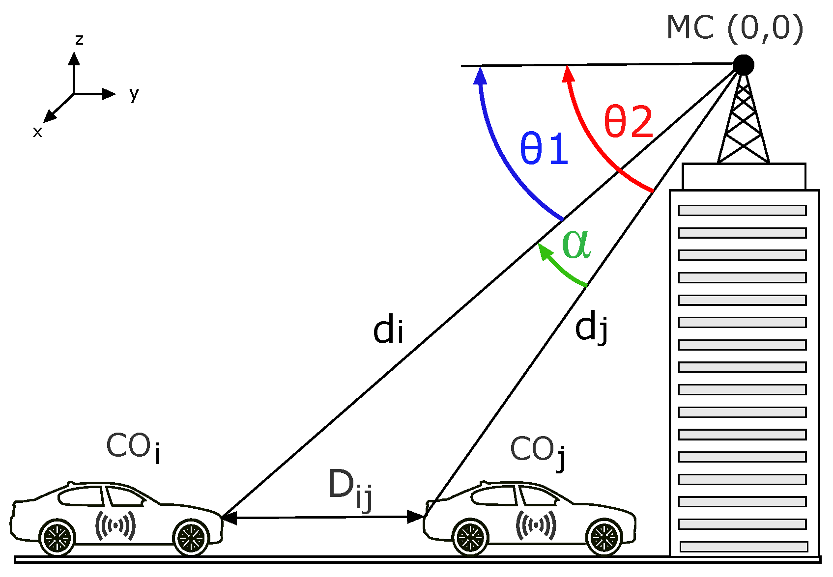
Figure 1. Angle orientation with Micro-cell.
Electronics 10 02750 g001
Figure 2. The basic model of assessment.
Electronics 10 02750 g002
Figure 3. Minimum Mean Square Error.
Electronics 10 02750 g003
Figure 4. Distribution of the obtained errors.
Electronics 10 02750 g004
Figure 5. Error probability followed by the distance.
Electronics 10 02750 g005
Figure 6. Cramer Rao Lower Bound compared to simulation results.
Electronics 10 02750 g006
Table 1. The 5G NR Rel.15 Simulation Parameters.
System ParameterParameter Value
Channel modeTDL-D
Bandwidth20 MHz
Number of subcarriers3300
Extended Cyclic Prefix2048
Subcarrier spacing60 kHz
Table 2. Performance and complexity comparison.
Recent Works5G ComplianceComplexityAccuracy (m)Additional Data
Our workcompliant O ( n 2 ) [0.55, 1]No
Wang et al. [22]compliant O ( n 2 ) n/aLearning Data
Kim et al. [23]compliant O ( n 3 ) n/aNo
Publisher’s Note: MDPI stays neutral with regard to jurisdictional claims in published maps and institutional affiliations.