Article

Educational Low-Cost C-Band FMCW Radar System Comprising Commercial Off-the-Shelf Components for Indoor Through-Wall Object Detection

Department of Electronics Engineering, College of Engineering, Pusan National University, Busan 46241, Korea
*
Author to whom correspondence should be addressed.
Electronics 2021, 10(22), 2758; https://doi.org/10.3390/electronics10222758
Submission received: 12 October 2021 / Revised: 8 November 2021 / Accepted: 9 November 2021 / Published: 11 November 2021
(This article belongs to the Section Microwave and Wireless Communications)

Abstract

:
This paper presents an educational low-cost C-band frequency-modulated continuous wave (FMCW) radar system for use in indoor through-wall metal detection. Indoor remote-sensing applications, such as through-wall detection and positioning, are essential for the comprehensive realization of the internet of things or super-connected societies. The proposed system comprises a two-stage radio-frequency power amplifier, a voltage-controlled oscillator, circuits for frequency modulation and system synchronization, a mixer, a 3-dB power divider, a low-noise amplifier, and two cylindrical horn antennas (Tx/Rx antennas). The antenna yields gain values in the 6.8~7.8 range when operating in the 5.83~5.94 GHz frequency band. The backscattered Tx signal is sampled at 4.5 kHz using the Arduino UNO analog-to-digital converter. Thereafter, the sampled signal is transferred to the MATLAB platform and analyzed using a customized FMCW radar algorithm. The proposed system is built using commercial off-the-shelf components, and it can detect targets within a 56.3 m radius in indoor environments. In this study, the system could successfully detect targets through a 4 cm-thick ply board with a measurement accuracy of less than 10 cm.

1. Introduction

There are numerous radar applications, such as radar-based range-breathing separation, monitoring of the worker activities, biomedical MIMO radars, radar systems for structural health monitoring, hand gesture recognition using micro-Doppler signatures, radars for unmanned aerial vehicles (UAVs), etc. Especially, radar technology is widely used in the military and internet of things (IoT) applications because it facilitates the development of remote-sensing equipment [1,2,3,4,5,6]. Military radars, such as those used in aerial defense, battlefield, and traffic-control operations, comprise large active phased-array systems to realize high-precision long-range detection (exceeding 100 km) and tracking [7,8,9]. Meanwhile, radars used in IoT applications are considerably smaller and lighter than their military counterparts because they are required to detect objects within an approximately 300 m range [10,11,12]. Recently, the development of compact integrated remote-sensing platforms for use in IoT applications, including healthcare, networking, and autonomous driving, has attracted increased industrial and academic research interest. For example, the radar systems used in automotive applications are among the most popular and fast-growing technologies owing to their superior detection capability compared with that of the lidar and vision-analysis techniques even under harsh environments involving rain or snow [13]. Additionally, the electromagnetic (EM)-field-based imaging and sensing technologies are widely investigated with regard to their household and disaster-control applications. The indoor positioning and object tracking are key technologies for future hyper-connected humancentric IoTs [14]. However, the low-cost implementation of high-performance radar systems remains a major technological challenge. The simultaneous consideration of the radar architecture and detection algorithms could facilitate the balancing of operation costs with respect to radar performance.
Several radar types exist, including the continuous wave Doppler, frequency-modulated continuous wave (FMCW), and pulsed radars, and each type affords several advantages and disadvantages to users [15]. The FMCW radar possesses a simple and low-complexity architecture. Furthermore, it can simultaneously detect the speed and distance of objects with high accuracy. These radars are widely employed in IoT applications because they do not require high computing power and data acquisition devices. These characteristics of the FMCW radar facilitate the design of low-cost, compact radar systems [16,17,18,19,20]. For instance, a simple FMCW radar system is proposed, but it is built using a high-cost lumped standalone RF component and audio input port of a PC in [21]. The audio input port has a high data sampling rate but requires a PC to process the received FMCW signal. This paper presents the development of a low-cost, compact FMCW radar system comprising commercial-off-the-shelf (COTS) components operating in the C-band (5.83–5.94 GHz) for educational purposes. The proposed system is intended for use in indoor positioning and through-wall applications, and it features a simple low-cost system architecture using the versatile Arduino platform. The proposed system is assembled on a 1-mm-thick FR4 printed circuit board (PCB) using the surface-mount technology. Arduino UNO—a well-known open-source, economical microcontroller platform—is used for data acquisition owing to its high scalability and suitability for use in many applications [22,23]. It is one of the most widely adopted IoT platforms due to its high scalability [24,25]. The radio-frequency front-end (RFFE) of the proposed radar and Arduino platform is synchronized using a customized modulator. The circular horn antennas are inspired by the antenna concept and designed based on the dominant-mode analysis. The proposed FMCW radar system costs less than USD 100.
The remainder of this paper is organized as follows. Section 2 describes the architecture of the proposed FMCW radar as well as details concerning the modulator, amplifiers, mixer, baseband circuit, and antennas. Additionally, the signal-processing algorithm for object detection is discussed. Section 3 discusses the measured performance of the proposed radar system. Finally, the major conclusions drawn from this study are presented in Section 4.

2. FMCW Radar System for Through-Wall Metal Detection

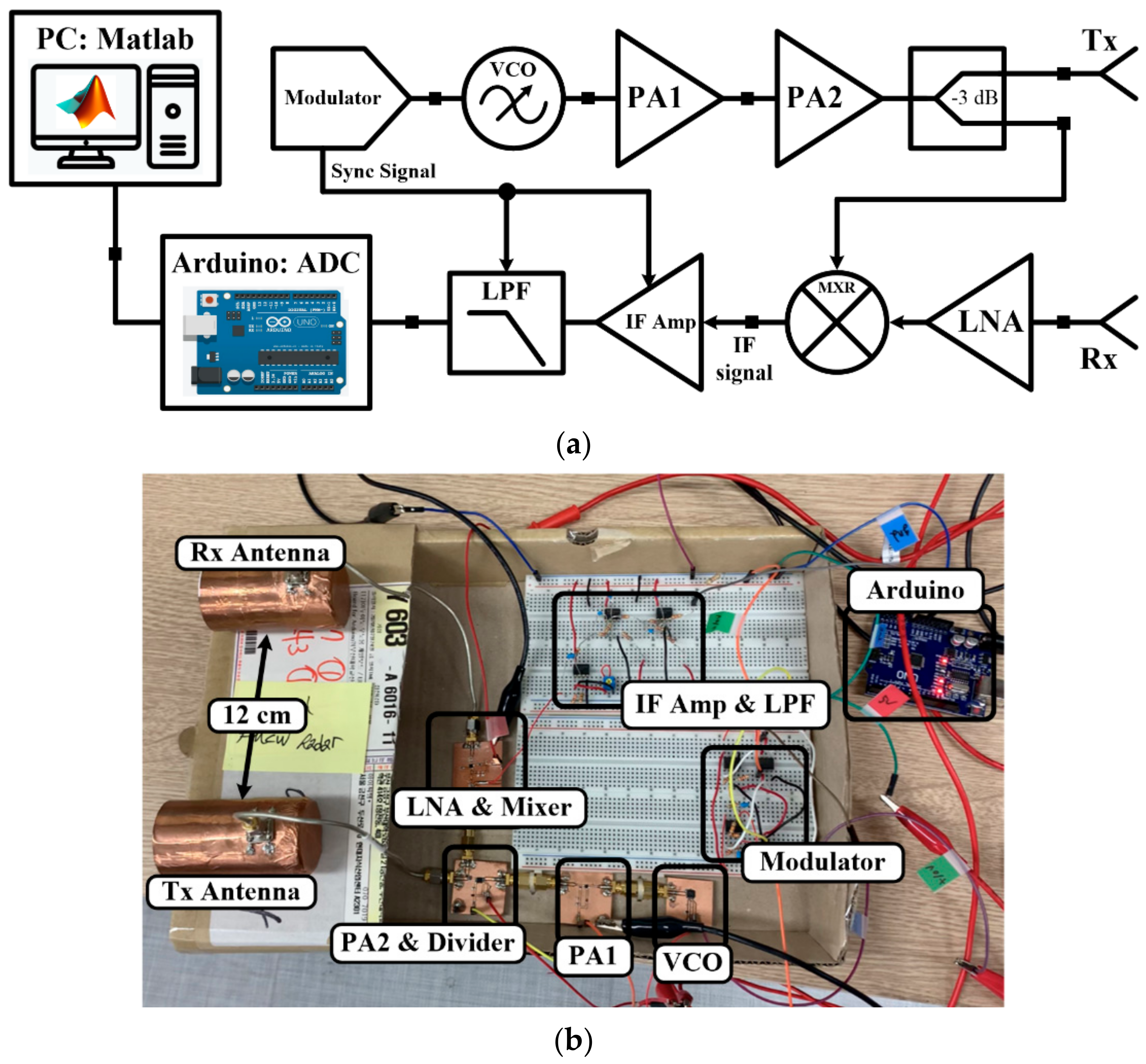
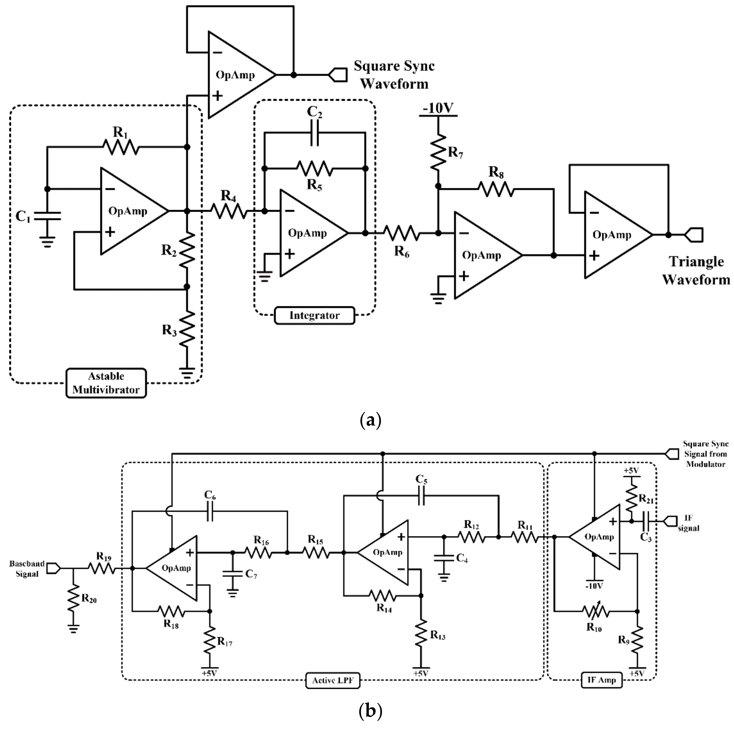
2.1. Low-Cost FMCW Radar System
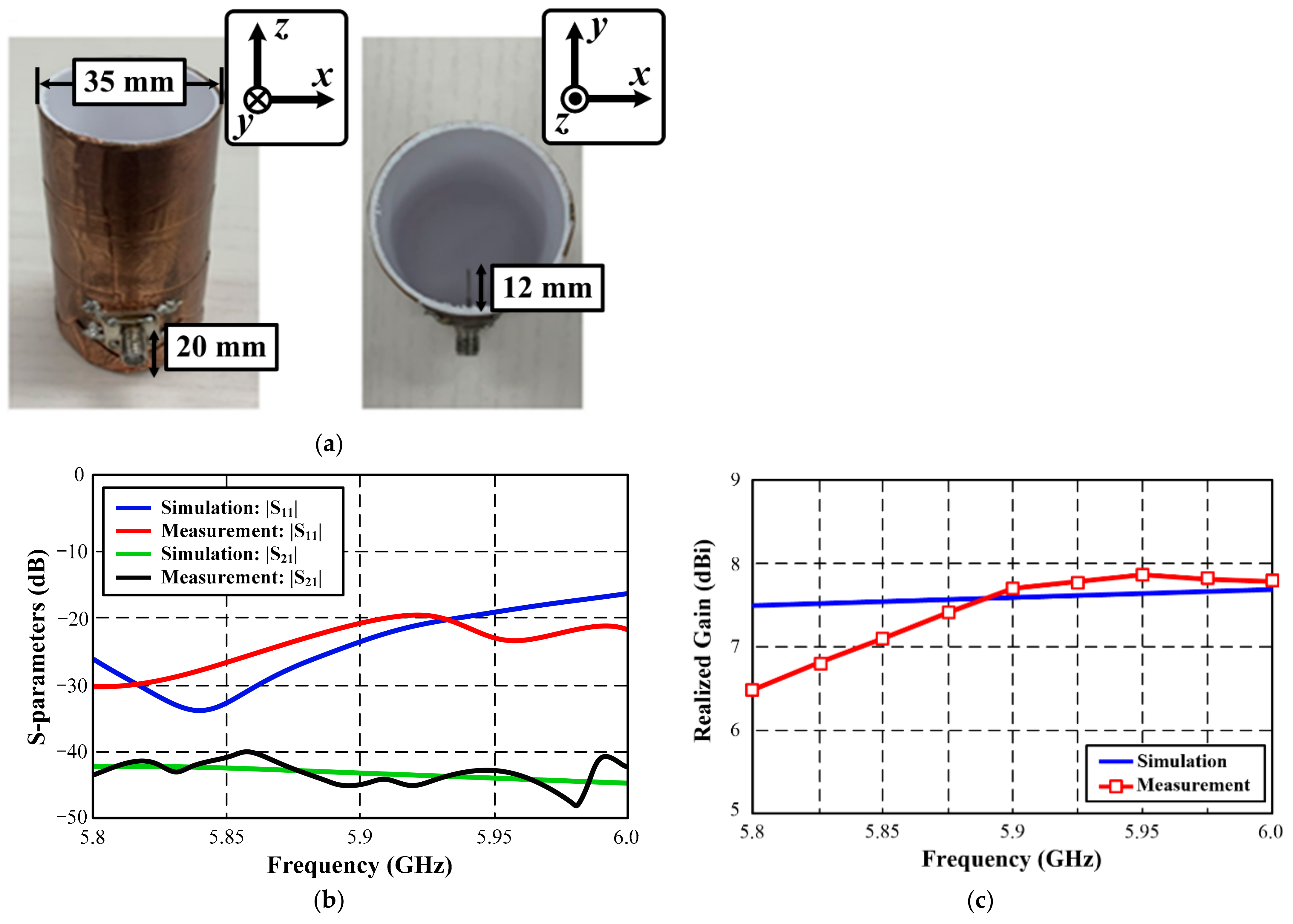
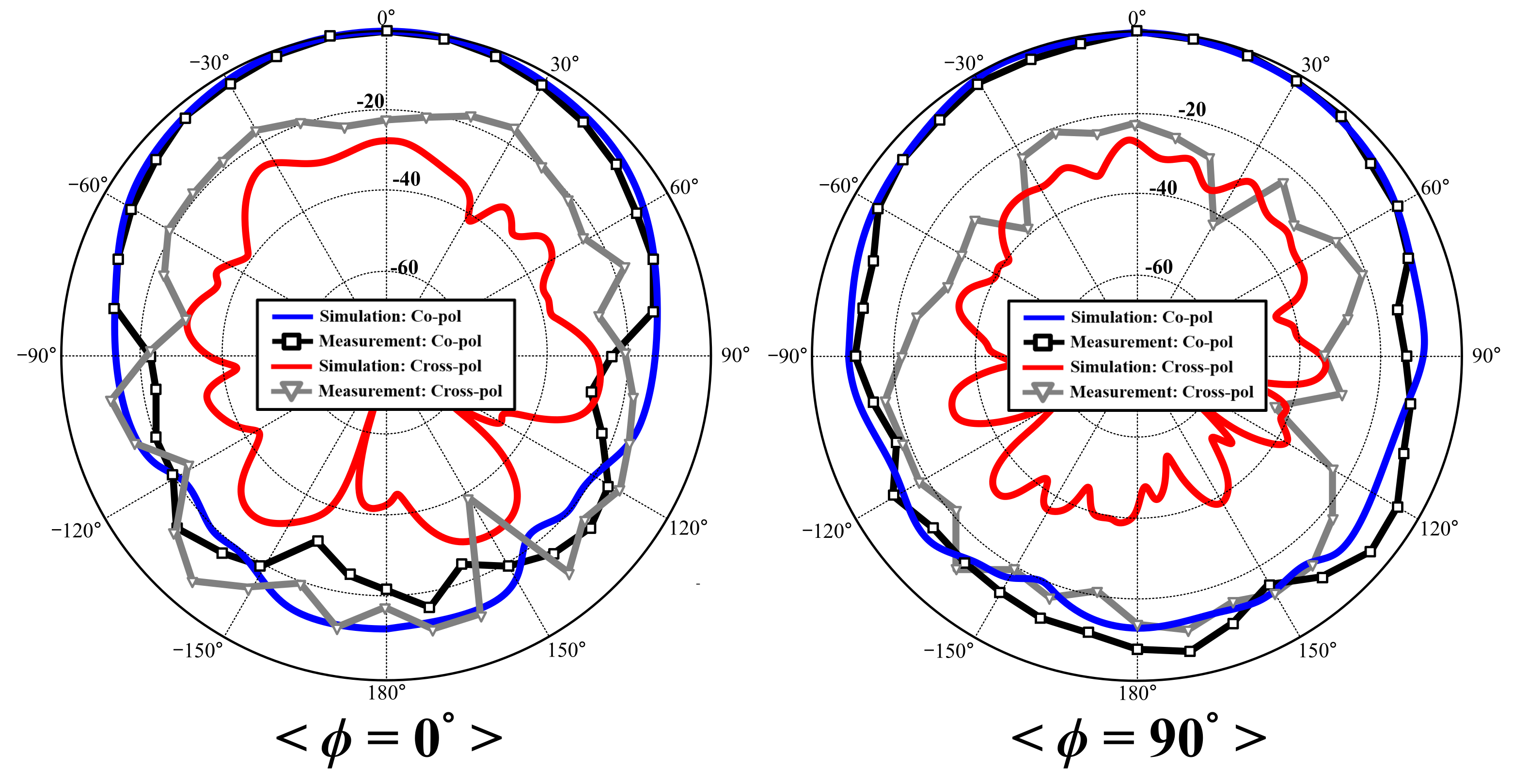
Figure 1 depicts the block diagram and prototype of the proposed low-cost radar system. The modulator generates a synchronization signal for the entire system and controls the voltage-controlled oscillator (VCO) for frequency modulation (FM). The Tx chain comprises a two-stage power amplifier (PA), power divider, and VCO (Figure 1a). In this configuration, the measured output signal power of the VCO (HMC431LP4ETR, Analog Devices [26]) equals 2 dBm, and the FM signal is amplified by the two-stage PA. The gain values of PA1 (GRF2505, Guerrilla RF [27]) and PA2 (HMC407MS8GE, Analog Devices [28]) equal 11.5 dB and 10 dB, respectively. Each PA possesses sufficient bandwidth to cover the VCO-generated FMCW signal. The measured insertion loss of the power divider (PD4859J5050S2HF, Anaren [29]) equals 0.7 dB in the C-band. The power delivered to the antenna equals 19.8 dBm, and an identical RF power is transferred to the mixer. The Rx chain comprised a low-noise amplifier (LNA) and mixer because the proposed radar uses a homodyne Rx system. The LNA (QPL9503TR7, Qorvo [30]) yields 21.6 dB gain, and its noise figure equals 1 dB at room temperature (25 °C). The amplified Rx signal is downconverted by the mixer (HMC218BMS8GE, Analog Devices [31]) to generate a baseband signal. The proposed system employs direct conversion to achieve a baseband signal frequency in the 0~1.5 kHz range. The baseband signal is amplified by the intermediate frequency (IF) amplifier and filtered by an active fourth-order low-pass filter (LPF). The 3-dB bandwidth (BW) of the LPF lies in the 0~1.5 kHz range to reject the out-of-band high-order harmonics and noise. Subsequently, the filtered baseband signal is sampled and brought into the MATLAB (MathWorks®, USA) platform using the Arduino UNO analog-to-digital converter (ADC) at 4.5 kHz frequency. This sampling frequency is sufficient to recover signals with a BW of up to 1.5 kHz. In the proposed system, the modulator, LPF, and IF amplifier circuits are designed using the same operational-amplifier OpAmp units (TLE2062, Texas Instruments [32]). Table 1 lists all COTS components used in the proposed system.
Figure 2 illustrates the modulator and baseband circuits of the proposed system. The modulator comprises an astable multivibrator and integrator for square and triangular wave generation, respectively. The square wave is characterized by a 50 ms period, and it synchronizes the baseband amplifier and active filter. The baseband stage, which comprises the IF amplifier and LPF, transmits the Rx signal to the Arduino because the microcontroller exclusively accepts positive voltages. Therefore, upon attainment of a positive voltage, the synchronizing square signal activates the baseband circuit. Subsequently, this square signal is transformed into a triangular wave by the integrator. The period of the triangular voltage wave also equals 50 ms. This triangular voltage wave controls the VCO, which subsequently generates an FM signal. Figure 3a depicts the time history of the generated voltage waveforms. Figure 3b reveals that the VCO output frequency is a function of the tuning voltage (Vt). The nearly linear increase in the VCO output frequency with increase in Vt can be modeled as the linear expression, as follows:
f 0 = 0.11 · V t + 5.4   GHz
As observed in this study, the VCO output frequency lies in the 5.83~5.94 GHz range, which corresponds to Vt values in the 3.88~4.93 V range. Table 1 lists the resistance and capacitance values of all COTS components used in the proposed system. The active LPF is designed using the conventional active-filter design principle. It comprises two second order LPF filters to reject noise signals and high-order harmonics. The 3-dB bandwidth of the fourth order LPF lies in the 0~1.5 kHz range.

2.2. Antenna Design

The cylindrical horn antennas used in the proposed system were designed based on the dominant-mode analysis. A commercial product package was used to this end, and it was metalized using a copper tape, as illustrated in Figure 4a. The simulations were performed using the Ansys HFSS 2021 R2 package. The horn antennas measured 35 × 88 mm (diameter × height), and they operated in a single dominant TM11 propagation mode in the 5~6.6 GHz frequency range. A 12 mm-long feeding probe was mounted 20 mm away from a shorting wall. All antenna parameters were measured inside an anechoic chamber. The measured antenna S-parameters cover the required operation frequency band of 5.83~5.94 GHz, and the isolation between the Rx and Tx antennas equals 40 dB when the distance between them equals 12 cm (Figure 1b and Figure 4b). The measured antenna gain values lie in the 6.8~7.8 dB range, and the cross-pol suppression level exceeds 20 dB at the rated operation frequency (Figure 4c). Figure 5 depicts the observed radiation patterns in the E- and H-planes (ϕ = 0° and ϕ = 90°, respectively). All measurements demonstrate good agreement with the simulation results.

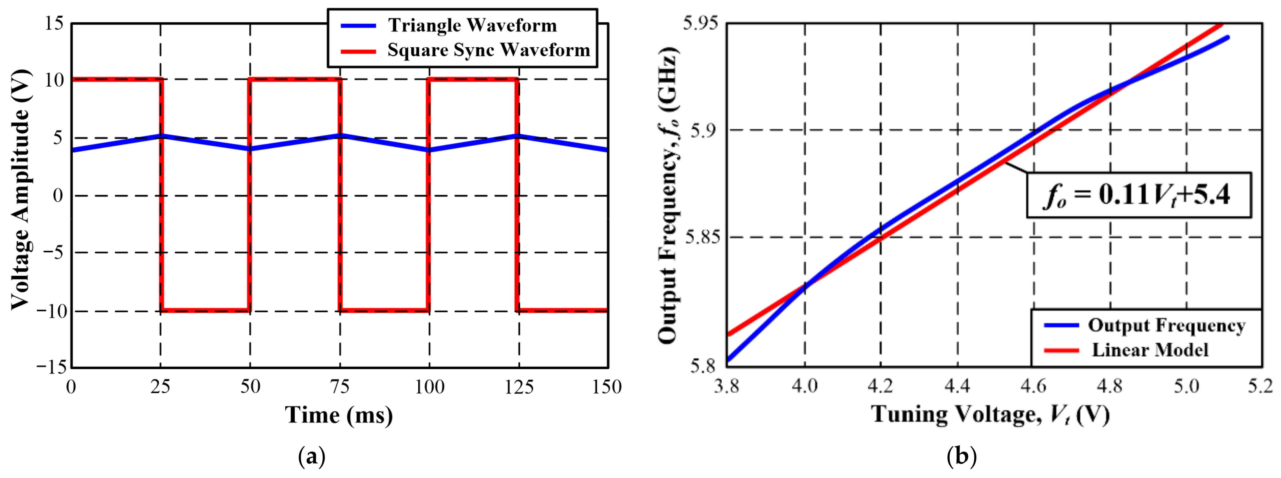
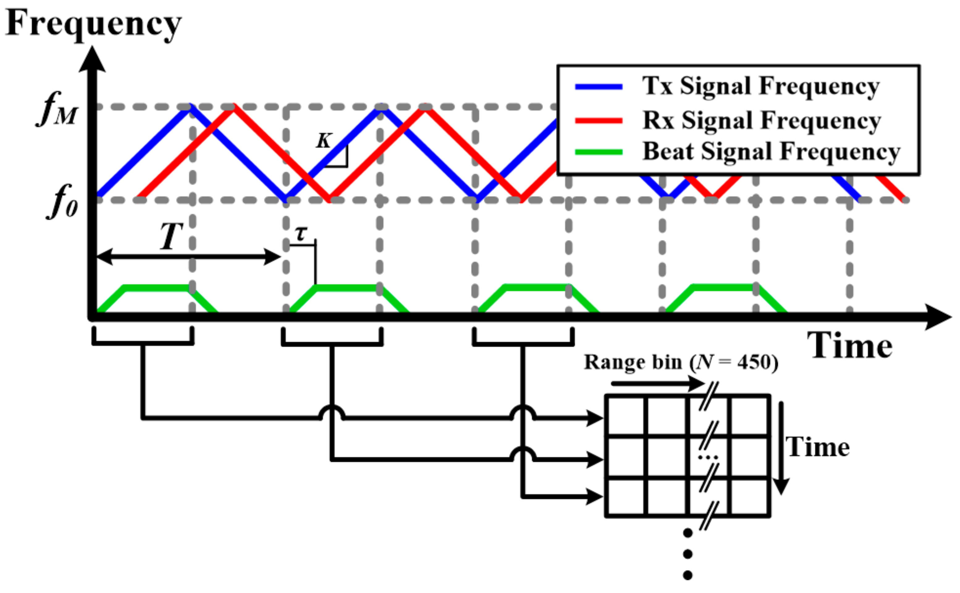
2.3. Operating Principle of Proposed FMCW Radar

The Arduino UNO ADC used in this study operates at a 4.5 kHz sampling rate, thereby limiting the FMCW radar bandwidth to 2.25 kHz in accordance with the Nyquist sampling theorem. The bandwidth of the proposed FMCW radar system equals 1.5 kHz, which is lower than the above-mentioned limit. The VCO output frequency (fT) as a function of time T could be expressed as
f T = f 0 + K · t ( 0 t < T / 2 ) f M K · t ( T / 2 t < T )
where f0 and fM denote the lowest and highest frequencies, respectively, and K denotes the time rate of increase of the triangular wave. As described in (3), the received signal frequency (fR) is delayed by τ = 2·R/c where R denotes the distance between the radar and detection target and c denotes the speed of light (c = 3 × 10⁸ m/s).
f R t = f T t τ
The down-converted signal is filtered by the active LPF over half the square-wave period (T/2), thereby producing a beat signal frequency, as illustrated in Figure 6. This beat signal frequency (fB) can be expressed as
f B t = f T t f R t
where fT and fR denote the Tx and Rx signal frequencies, respectively. The time-domain data of the beat signal are sampled using the Arduino UNO ADC at 4.5 kHz and sent to a PC via serial communication. The duration of the beat signal is 25 ms. Each i-th range bin (SBB(i, N)) stores 450 data points (N = 450) because they comprise 112.5 beat signal data points. The remaining 337.5 sample points represent zero-padded data, as described in Figure 6. The zero-padded data format increases signal smoothness in the frequency domain [33]. The proposed FMCW radar system requires DC offset filtering because it uses a homodyne system. As described in (5), DC offset can be removed from the baseband signal by subtracting the averaged value (Save) of each data stored in the range bin.
S B B i , N = S B B i , N S a v e
Thus, a new DC-offset-removed range bin S B B i , N is created, and a range-time intensity (RTI) graph can be plotted based on the magnitude of the new fast-Fourier-transformed (FFT) range bin.

3. Experimental Results

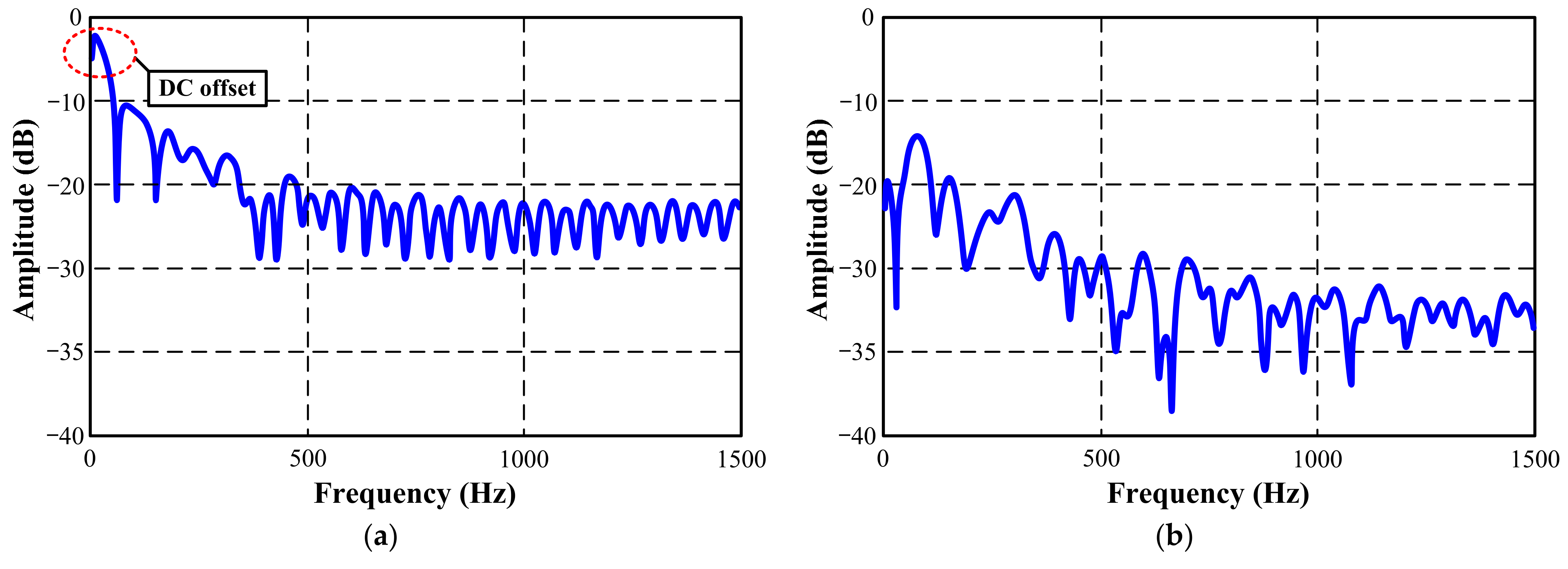
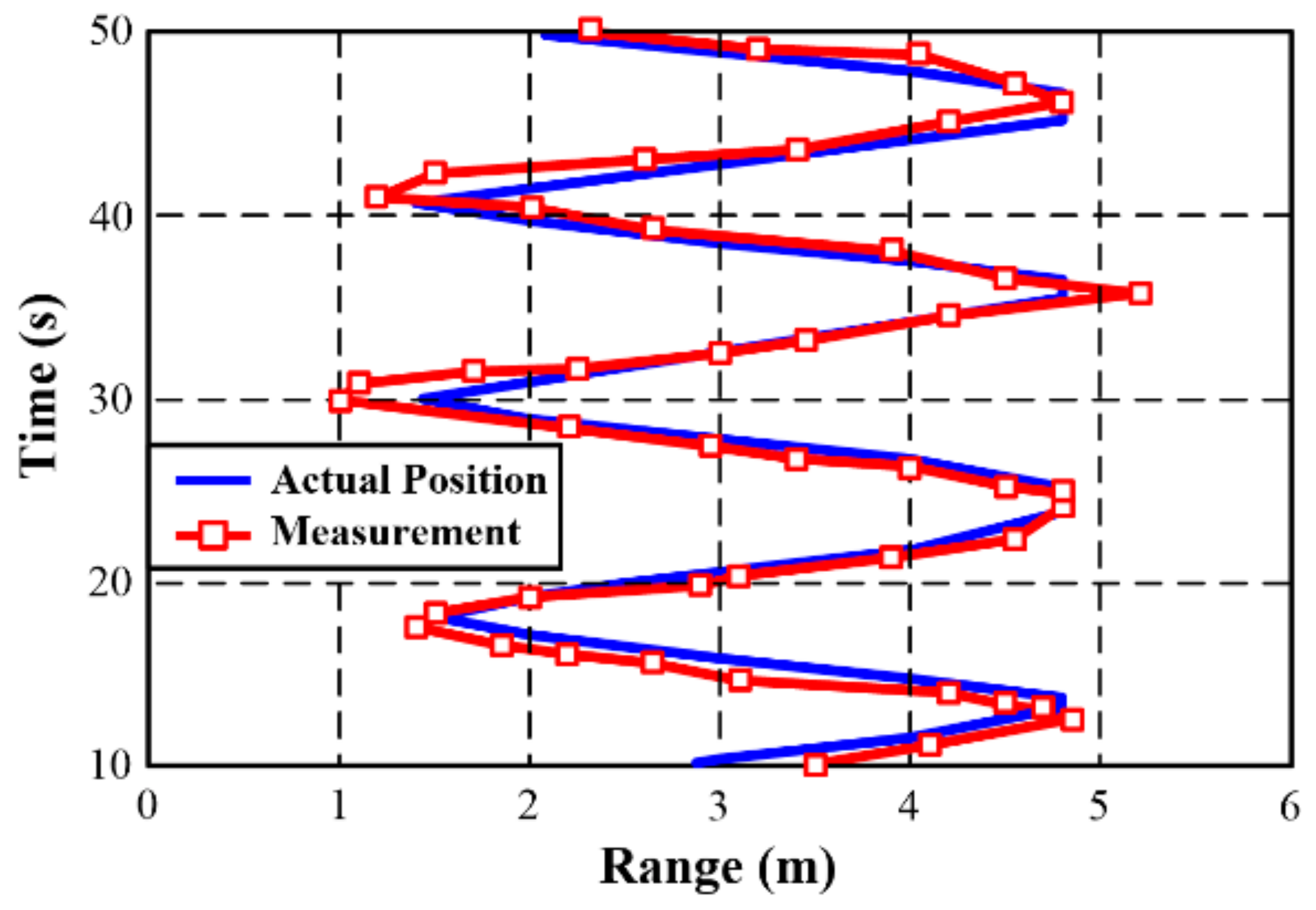
3.1. Indoor FMCW Radar Measurement

The performance of the proposed low-cost FMCW radar system was verified in an indoor environment maintained at 25 °C. A 30 × 30 cm2 copper plate was placed facing the radar, and the distance between them was measured. As observed, the DC offset was successfully removed, and the peak-signal strength was clearly observed to facilitate distance measurement. Figure 7 illustrates the effect of the DC offset removal described in (5). The time-varying distance (R) between the radar and object can be calculated as follows. In (6), B denotes bandwidth of the proposed FMCW radar system, fB is beat frequency, T is frequency rising time, and c is the speed of light.
R = f B · c · T / 2 · B
The maximum detection range (RM) of the proposed FMCW radar is realized when the beat frequency of the FMCW radar equals fB. In this study, the value of RM equaled 56.3 m, which is sufficient in an indoor environment. The theoretical range resolution (Rres) of the proposed FMCW radar system (BW: 110 MHz) equals 1.36 m, as described in (7). It can be improved by using the broad bandwidth.
R r e s = c / 2 · B
Figure 8 depicts plots of the measured and actual positions of a metallic object in the range–time space. In this study, the piecewise cubic Hermite interpolating polynomial (PCHIP) was employed to extract distance data from the measured range bin. As observed, the average range error equals 0.37 m, which is less than the distance resolution.

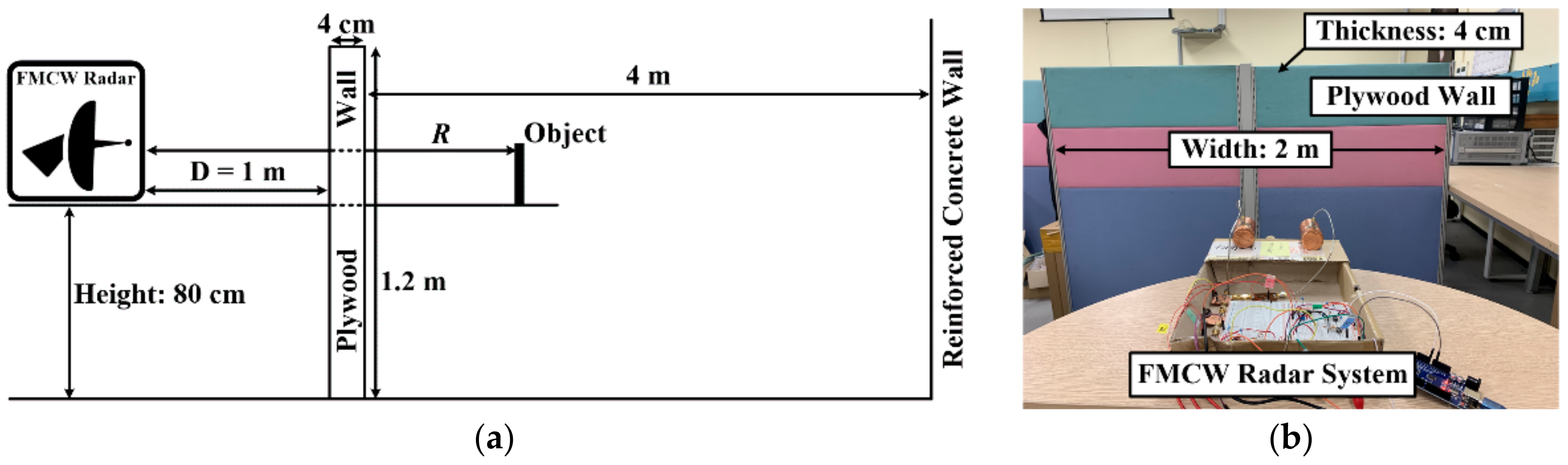
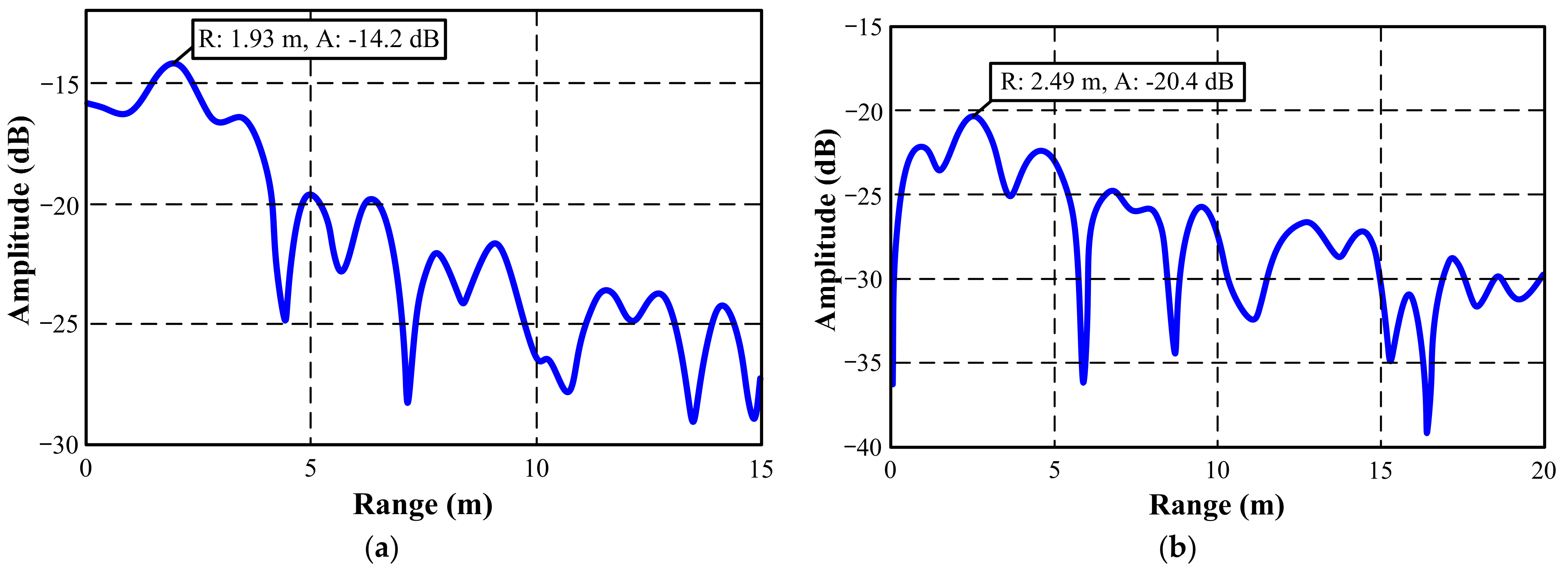
3.2. Through-Wall Detection

To validate the through-wall detection capability of the proposed system, the FMCW radar system was used to detect a metallic object through a 4 cm-thick plywood wall (Figure 9). The FMCW radar and target were placed on an 80 cm-high wooden table. A 4 cm-thick plywood was placed at 1 m away from the radar. The width and height of the plywood equaled 2 m and 1.2 m, respectively. Subsequently, a metallic object was placed behind the wall, and the Rx signal was analyzed using the previously described algorithm. The object was placed at value of R in the 2.5~4 m range, as depicted in Figure 9a, and the corresponding measurement results are depicted in Figure 10. They show FFT magnitude of signal stored in the range bin over the range. As can be seen, the maximum error between the actual and estimated positions equals 10 cm, and the average range error equals 5.6 cm. The proposed FMCW radar system demonstrates a high range accuracy of 5.6 cm, albeit its corresponding range resolution equals 1.4 m.

4. Conclusions

This paper presents a low-cost C-band FMCW radar system based on the Arduino platform and designed using COTS components for educational purposes. It incorporates a simplified modulator circuit for VCO control and baseband-circuit synchronization. The circular Tx and Rx antennas are designed based on the dominant-mode analysis of commercial product packages. The results of this study reveal that the proposed PCHIP-based range-estimation algorithm significantly improves the range-measurement accuracy. The performance of the proposed system has been verified by performing metallic object-detection experiments in an indoor environment with and without a large plywood wall, thereby demonstrated its through-wall detection capability. The proposed FMCW radar system, including the PCB, ICs, resistors, and MLCCs, costs less than USD 100. Overall, the proposed educational low-cost FMCW radar represents a scalable technology that can be utilized in several applications, such as indoor IoTs.

Author Contributions

Conceptualization, S.K.; validation, H.J. All authors have read and agreed to the published version of the manuscript.

Funding

This work was supported by the National Research Foundation of Korea (NRF) grant funded by the Korea Government (MSIT) under Grant 2020R1C1C1003362.

Institutional Review Board Statement

Not applicable.

Conflicts of Interest

The authors declare no conflict of interest.

References

  1. Luong, N.C.; Lu, X.; Hoang, D.T.; Niyato, D.; Kim, D.I. Radio Resource Management in Joint Radar and Communication: A Comprehensive Survey. IEEE Commun. Surv. Tutor. 2021, 23, 780–814. [Google Scholar] [CrossRef]
  2. Sarkar, T.K.; Palma, M.S.; Mokole, E.L. Echoing Across the Years. IEEE Microw. Mag. 2016, 17, 46–60. [Google Scholar] [CrossRef]
  3. Cardillo, E.; Li, C.; Caddemi, A. Embedded Heating, Ventilation, and Air Conditioning Control Systems: From Traditional Technologies Towards Radar Advanced Sensing. Rev. Sci. Instrum. 2021, 92, 1–14. [Google Scholar] [CrossRef] [PubMed]
  4. Cardillo, E.; Caddemi, A. Insight on Electronic Travel Aids for Visually Impaired People: A Review on the Electromagnetic Technology. Electronics 2019, 8, 1281. [Google Scholar] [CrossRef] [Green Version]
  5. Yang, D.; Zhu, Z.; Liang, B. Vital Sign Signal Extraction Method Based on Permutation Entropy and EEMD Algorithm for Ultra-Wideband Radar. IEEE Access 2019, 7, 178879–178890. [Google Scholar] [CrossRef]
  6. Yang, D.; Zhu, Z.; Zhang, J.; Liang, B. The Overview of Human Localization and Vital Sign Signal Measurement Using Handheld IR-UWB Through-Wall Radar. Sensors 2021, 21, 402. [Google Scholar] [CrossRef]
  7. Hodges, R.E.; Chen, J.C.; Radway., M.R.; Amaro., L.R.; Khayatian, B.; Munger, J. An Extremely Large Ka-Band Reflectarray Antenna for Interferometric Synthetic Aperture Radar. IEEE Antennas Propag. Mag. 2020, 62, 23–33. [Google Scholar] [CrossRef]
  8. Adrian, O. M3R AESA Technology for Extended Air Defense. IEEE Aerosp. Electron. Syst. Mag. 2010, 23, 11–16. [Google Scholar] [CrossRef]
  9. Porras, M.J.P.; Bertuch, T.; Loecker, C.; Adams, R.; Wunderlich, R.; Heinen, S. An AESA Antenna Comprising an RF Feeding Network with Strongly Coupled Antenna Ports. IEEE Trans. Antennas Propag. 2015, 63, 182–194. [Google Scholar] [CrossRef]
  10. Park, J.K.; Hong, Y.; Lee, H.; Jang, C.; Yun, G.H.; Lee, H.J.; Yook, J.G. Noncontact RF Vital Sign Sensor for Continuous Monitoring of Driver Status. IEEE Trans. Biomed. Circuits Syst. 2019, 13, 493–502. [Google Scholar] [CrossRef]
  11. Mazzinghi, A.; Freni, A.; Agostini, A.; Bossio, L.; Albani, M. Industrial Antenna Development for 77-GHz Level-Crossing Monitoring Radar. IEEE Antennas Propag. Mag. 2018, 60, 95–106. [Google Scholar] [CrossRef]
  12. Toker, O.; Alsweiss, S. Design of a Cyberattack Resilient 77 GHz Automotive Radar Sensor. Electronics 2020, 9, 573. [Google Scholar] [CrossRef] [Green Version]
  13. Xu, Z.; Zhao, J.; Zhang, F.; Zhang, L.; Yang, T.; Li, Q.; Pan, S. Photonics-Based Radar-Lidar Integrated System for Multi-Sensor Fusion Applications. IEEE Sens. J. 2020, 20, 15068–15078. [Google Scholar] [CrossRef]
  14. Akanm, O.B.; Arik, M. Internet of Radars: Sensing versus Sending with Joint Radar-Communications. IEEE Commun. Mag. 2020, 58, 13–19. [Google Scholar]
  15. Jankiraman, M. FMCW Radar Design; Artech House: Norwood, MA, USA, 2008. [Google Scholar]
  16. Ryu, S.J.; Suh, J.S.; Baek, S.H.; Hong, S.; Kim, J.H. Feature-Based Hand Gesture Recognition Using an FMCW Radar and Its Temporal Feature Analysis. IEEE Sens. J. 2018, 18, 7593–7602. [Google Scholar] [CrossRef]
  17. Park, K.; Lee, J.; Kim, Y. Deep Learning-Based Indoor Two-Dimensional Localization Scheme Using a Frequency-Modulated Continuous Wave Radar. Electronics 2021, 10, 2166. [Google Scholar] [CrossRef]
  18. Maitra, S.; Gartley, M.G.; Kerekes, J.P. A Low-Cost Laboratory-Based Polarimetric Synthetic Aperture Radar System for Scattering Analysis. IEEE Antennas Propag. Mag. 2017, 59, 130–141. [Google Scholar] [CrossRef]
  19. Peng, Z.; Li, C. Portable Microwave Radar Systems for Short-range Localization and Life Tracking: A Review. Sensors 2019, 19, 1136. [Google Scholar] [CrossRef] [Green Version]
  20. Wang, T.; Li, P.; Wang, M.; Yang, D.; Shi, C. A Flexible, Efficient and Low-cost Experimental Platform for FMCW Radars. Sensor Rev. 2019, 39, 495–503. [Google Scholar] [CrossRef]
  21. Build a Small Radar System Capable of Sensing Range, Doppler, and Synthetic Aperture Radar Imaging. Available online: https://ocw.mit.edu/resources/res-ll-003-build-a-small-radar-system-capable-of-sensing-range-doppler-and-synthetic-aperture-radar-imaging-january-iap-2011/ (accessed on 9 November 2021).
  22. Llorens, J.L.S.; Merino, J.J.G.; Benabdeloued, B.Y.N.; Cintas, S.R.; Zamora, J.O.; Caturla, J.J.G. Design and Implementation of an Arduino-Based Plug-and-Play Acquisition System for Seismic Noise Measurements. Electronics 2019, 8, 1035. [Google Scholar] [CrossRef] [Green Version]
  23. Kim, S.M.; Choi, Y.; Suh, J. Applications of the Open-Source Hardware Arduino Platform in the Mining Industry: A Review. Appl. Sci. 2020, 10, 5018. [Google Scholar] [CrossRef]
  24. Lin, Y.W.; Lin, Y.B.; Yang, M.T.; Lin, J.H. ArduTalk: An Arduino Network Application Development Platform Based on IoTtalk. IEEE Syst. J. 2017, 13, 168–476. [Google Scholar] [CrossRef]
  25. Dhingra, S.; Madda, R.B.; Gandomi, A.H.; Patan, R.; Daneshmand, M. Internet of Things Mobile–Air Pollution Monitoring System (IoT-Mobair). IEEE Internet Things J. 2019, 6, 5577–5584. [Google Scholar] [CrossRef]
  26. HMC431LP4/431LP4E Datasheet. Available online: https://www.analog.com/media/en/technical-documentation/data-sheets/hmc431.pdf (accessed on 9 November 2021).
  27. GRF2505 Datasheet. Available online: https://www.guerrilla-rf.com/products/detail/sku/GRF2505 (accessed on 9 November 2021).
  28. HMC407MS8G/407MS8GE Datasheet. Available online: https://www.analog.com/media/en/technical-documentation/data-sheets/hmc407.pdf (accessed on 9 November 2021).
  29. PD4856 Datasheet. Available online: https://www.mouser.com/ProductDetail/Anaren/PD4859J5050S2HF?qs=61pwXRo0i5ij 9Ns6s%2Fy2Jw%3D%3D (accessed on 9 November 2021).
  30. QPL9503 Datasheet. Available online: https://www.qorvo.com/products/d/da006028 (accessed on 9 November 2021).
  31. HMC218b Datasheet. Available online: https://www.analog.com/media/en/technical-documentation/data-sheets/hmc218b.pdf (accessed on 9 November 2021).
  32. TLE2062 Datasheet. Available online: https://www.ti.com/product/TLE2062 (accessed on 9 November 2021).
  33. Cormack, G.D.; Blair, D.A.; McMullin, J.N. Enhanced Spectral Resolution FFT for Step-like Signals. IEEE Trans. Instrum. Meas. 1991, 40, 34–36. [Google Scholar] [CrossRef]
Figure 1. Proposed Arduino-ADC-based low-cost FMCW radar system for through-wall detection: (a) system block diagram and (b) radar prototype.
Electronics 10 02758 g001
Figure 2. (a) Designed frequency modulator (FM) and (b) baseband circuits.
Electronics 10 02758 g002
Figure 3. Variation trends concerning (a) output signals obtained from proposed modulator and (b) VCO output frequency.
Electronics 10 02758 g003
Figure 4. Designed circular horn antenna: (a) fabricated antenna, (b) S-parameters, and (c) realized gain.
Electronics 10 02758 g004
Figure 5. Measured antenna radiation patterns.
Electronics 10 02758 g005
Figure 6. Operating principle of proposed FMCW radar.
Electronics 10 02758 g006
Figure 7. Amplitude of received signal in frequency domain (a) with and (b) without DC offset.
Electronics 10 02758 g007
Figure 8. Range–time intensity (RTI) of proposed FMCW radar in indoor environment.
Electronics 10 02758 g008
Figure 9. (a) Through-wall detection measurement setup and (b) measurement environment.
Electronics 10 02758 g009
Figure 10. Through-wall object-detection results: (a) R = 2 m, (b) 2.5 m, (c) 3 m, (d) 3.5 m, and (e) 4 m.
Electronics 10 02758 g010aElectronics 10 02758 g010b
Table 1. List of components used in the proposed FMCW radar system.
Passive Components
R122 kΩR210 kΩR310 kΩR451 kΩR5510 kΩ
R64.3 kΩR72.2 kΩR81 kΩR9220 ΩR1010 kΩ
R116.8 kΩR126.8 kΩR1312.1 kΩR141 kΩR156.8 kΩ
R166.8 kΩR171.62 kΩR182 kΩR1947 kΩR2047 kΩ
R2110 kΩC11 μFC21 μFC31 μFC410 nF
C510 nFC610 nFC710 nF
Publisher’s Note: MDPI stays neutral with regard to jurisdictional claims in published maps and institutional affiliations.

