
Half-Elliptical Resonator Lowpass Filter with a Wide Stopband for Low Band 5G Communication Systems


Abstract
:1. Introduction
2. LPF Design Process
2.1. Initial Low-Pass Filter
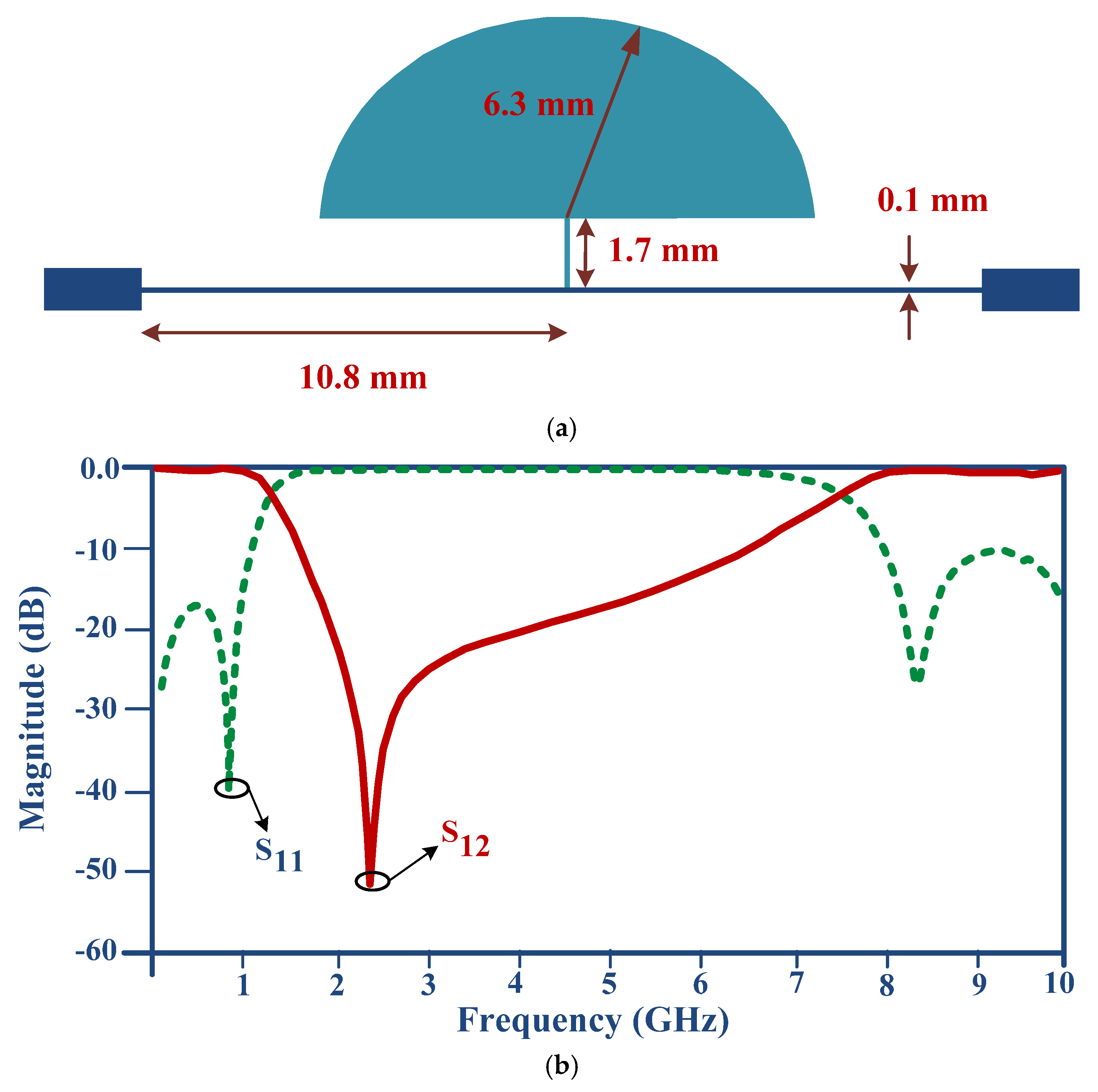
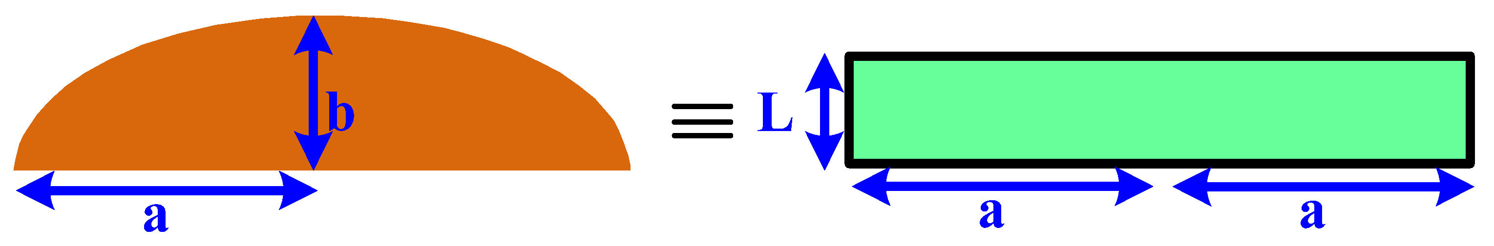
2.2. The Half-Elliptical Shaped Resonator Design
2.3. Two Elliptical Resonators Design
2.4. Attenuator Resonator Design
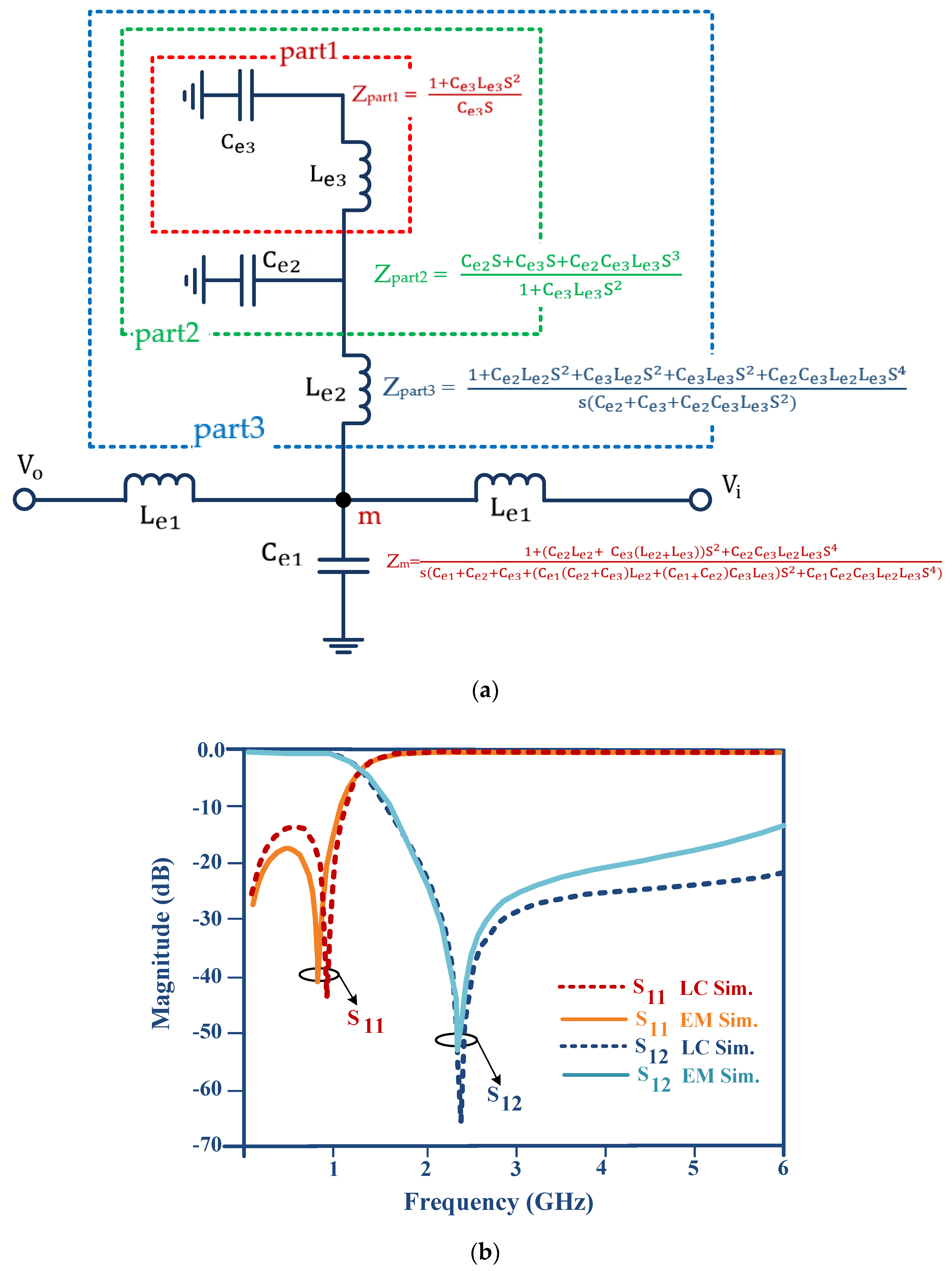
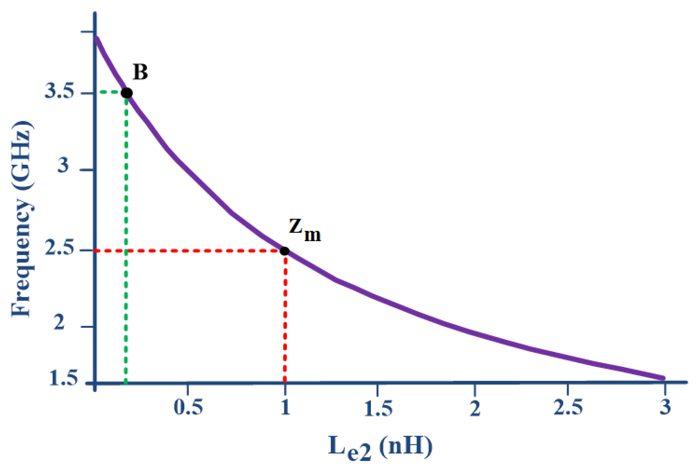
2.5. Design of the Proposed Filter
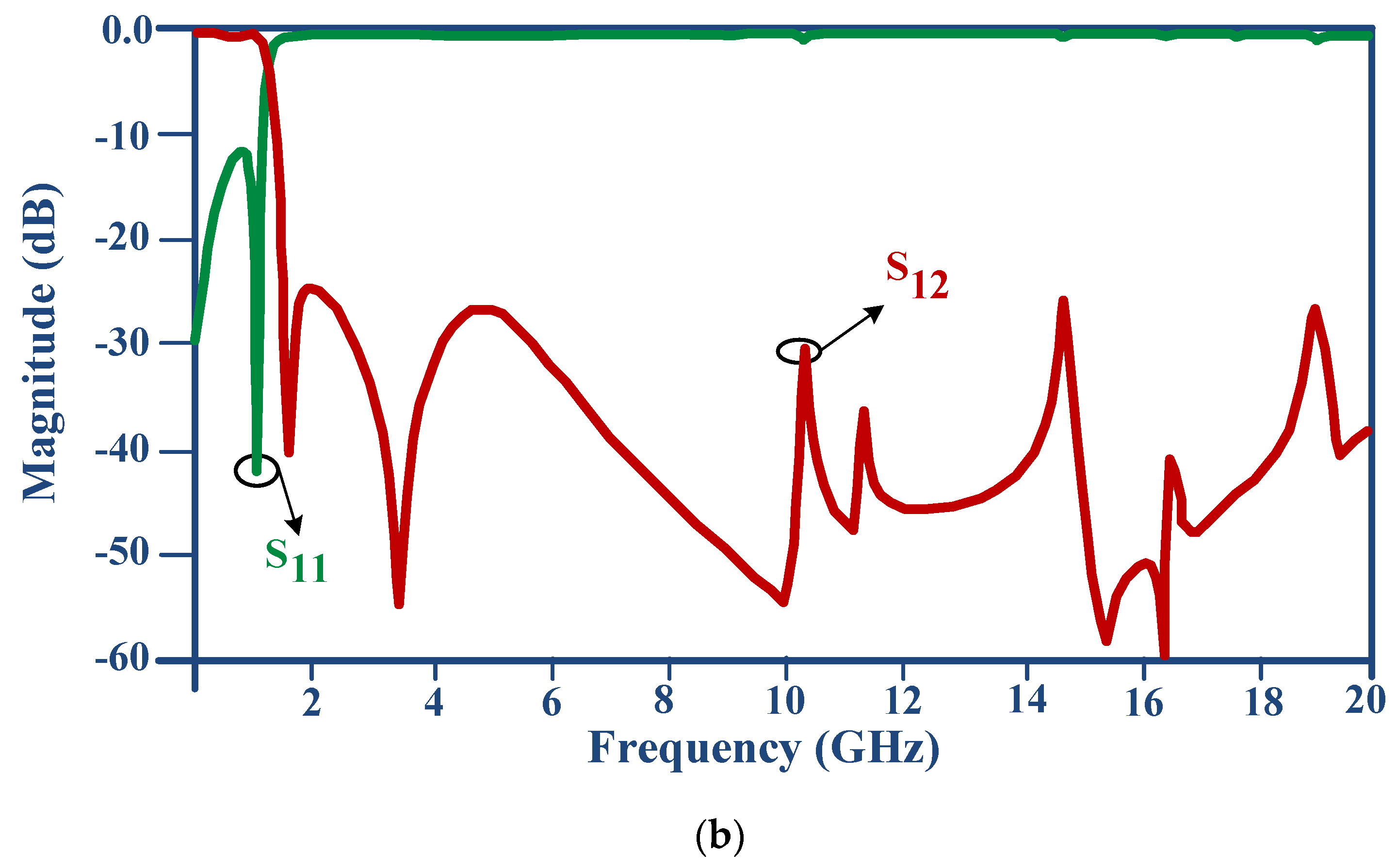
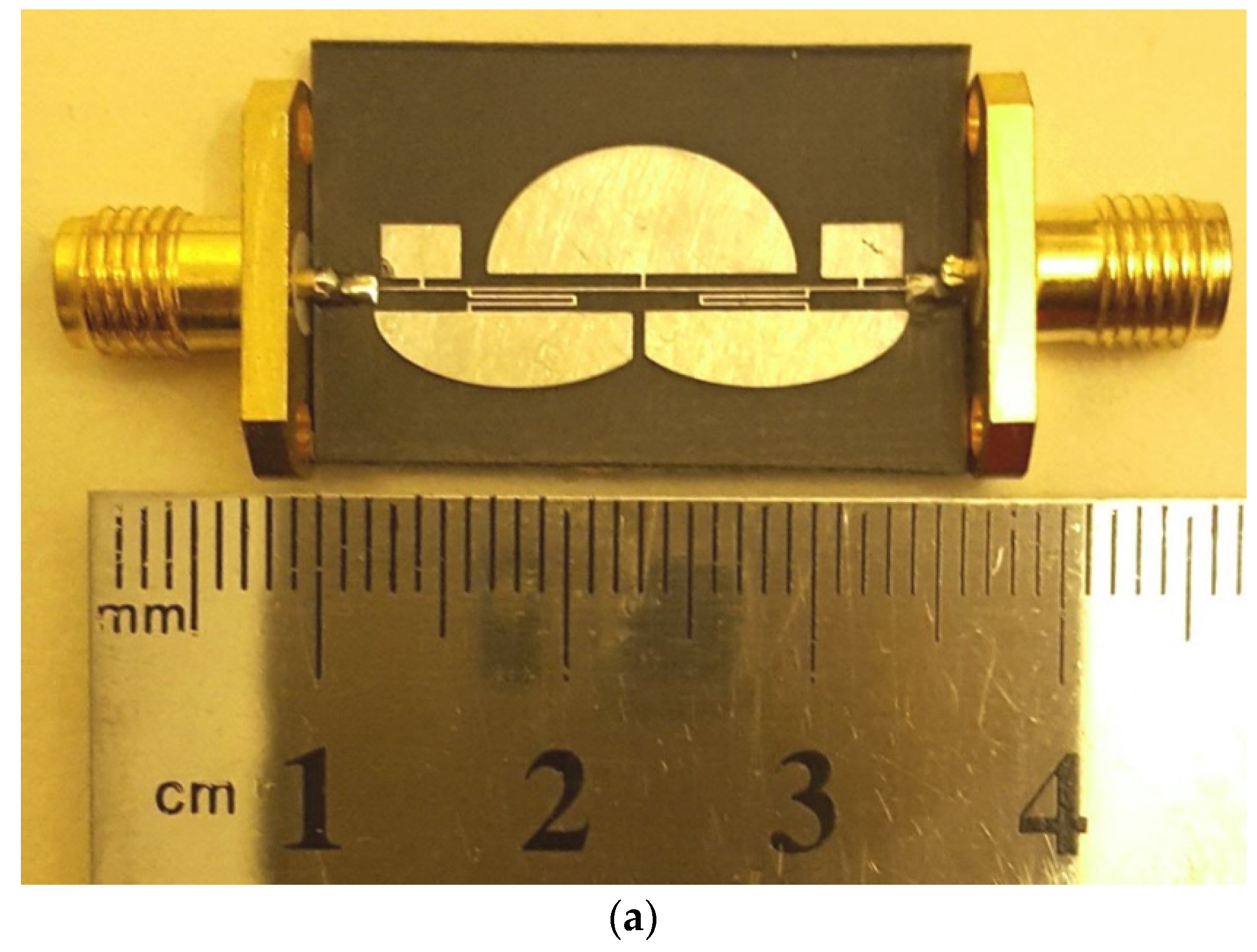
3. Implementation and Measurement Results
4. Conclusions
Author Contributions
Funding
Data Availability Statement
Conflicts of Interest
References
- Kumar, L.; Parihar, M.S. A Wide Stopband Low-Pass Filter With High Roll-Off Using Stepped Impedance Resonators. IEEE Microw. Wirel. Compon. Lett. 2018, 28, 404–406. [Google Scholar] [CrossRef]
- Jadhav, S.A.; Misal, S.B.; Mishra, A.; Murugkar, A. Designing of stepped impedance Butterworth and Chebyshev filters for wireless communication. In Proceedings of the 2017 IEEE Applied Electromagnetics Conference (AEMC), Aurangabad, India, 19–22 December 2017; IEEE: Manhattan, NY, USA, 2017; pp. 1–2. [Google Scholar]
- Golestanifar, A.; Roshani, S. Design of an ultra-sharp composite low-pass filter using analytical method. Analog. Integr. Circuits Signal Process. 2018, 100, 249–255. [Google Scholar] [CrossRef]
- Joy, J.T.; Sumi, M.; Harikrishanan, A.I. Low pass filters with stepped impedance resonators and DGS structures. In Proceedings of the 2017 International Conference on Inventive Communication and Computational Technologies (ICICCT), Coimbatore, India, 10–11 March 2017; IEEE: Manhattan, NY, USA, 2017; pp. 59–61. [Google Scholar]
- Hookari, M.; Roshani, S.; Roshani, S. Design of a low pass filter using rhombus-shaped resonators with an analytical LC equivalent circuit. Turk. J. Electr. Eng. Comput. Sci. 2020, 28, 865–874. [Google Scholar] [CrossRef]
- Li, C.; Peng, W.; Wang, Z.; Lai, H. An Ultra Wide-Stopband Lowpass Filter Using Smooth Transmission Line. In Proceedings of the 2018 International Conference on Microwave and Millimeter Wave Technology (ICMMT), Chengdu, China, 7–11 May 2018; IEEE: Manhattan, NY, USA, 2018; pp. 1–3. [Google Scholar]
- Lalbakhsh, A.; Alizadeh, S.M.; Ghaderi, A.; Golestanifar, A.; Mohamadzade, B.; Jamshidi, M.B.; Mandal, K.; Mohyuddin, W. A Design of a Dual-Band Bandpass Filter Based on Modal Analysis for Modern Communication Systems. Electronics 2020, 9, 1770. [Google Scholar] [CrossRef]
- Dehghani, K.; Karimi, G.; Lalbakhsh, A.; Maki, S. Design of lowpass filter using novel stepped impedance resonator. Electron. Lett. 2014, 50, 37–39. [Google Scholar] [CrossRef]
- Mousavi, S.M.H.; Makki, S.V.A.-D.; Raziani, S.; Siahkamari, H.; Malakooti, S.A. Vertical Response Microstrip Lowpass Filter Using Stepped Impedance Lines and Radial Resonators. Wirel. Pers. Commun. 2017, 97, 633–645. [Google Scholar] [CrossRef]
- Nasiri, B.; Errkik, A.; Zbitou, J.; Tajmouati, A.; Elabdellaoui, L.; Latrach, M. A novel design of a compact miniature microstrip low pass filter based on SRR. In Proceedings of the 2017 International Conference on Wireless Technologies, Embedded and Intelligent Systems (WITS), Fez, Morocco, 19–20 April 2017; IEEE: Manhattan, NY, USA, 2017; pp. 1–5. [Google Scholar]
- Parvez, S.; Sakib, N.; Mollah, N. Dumbbell annular ring with circular patterned microstrip low-pass filter with higher selectivity, wider stopband and lower insertion loss. In Proceedings of the 2015 2nd International Conference on Electrical Information and Communication Technologies (EICT), Khulna, Bangladesh, 10–12 December 2015; IEEE: Manhattan, NY, USA, 2015; pp. 373–377. [Google Scholar]
- Kumar, K.V.P.; Karthikeyan, S. Microstrip lowpass filter with flexible roll-off rates. AEU-Int. J. Electron. Commun. 2018, 86, 63–68. [Google Scholar] [CrossRef]
- Karimi, G.; Lalbakhsh, A.; Siahkamari, H. Design of Sharp Roll-Off Lowpass Filter With Ultra Wide Stopband. IEEE Microw. Wirel. Compon. Lett. 2013, 23, 303–305. [Google Scholar] [CrossRef]
- Ting, S.-W.; Tam, K.-W.; Martins, R. Miniaturized microstrip lowpass filter with wide stopband using double equilateral U-shaped defected ground structure. IEEE Microw. Wirel. Compon. Lett. 2006, 16, 240–242. [Google Scholar] [CrossRef]
- Sureshkumar, S.; Anand, P.M.R.; Prajapati, A.; Sankaran, K.S. Low Pass Filter Design with CSRR as Defected Ground Structure. In Proceedings of the 2018 International Conference on Communication and Signal Processing (ICCSP), Chennai, India, 3–5 April 2018; IEEE: Manhattan, NY, USA, 2018; pp. 893–896. [Google Scholar]
- Karimi, G.; Siahkamari, H.; Hamedani, F.K.; Lalbakhsh, A. Design of Modified Z-Shaped and T-Shaped Microstrip Filter Based on Transfer Function Analysis. Wirel. Pers. Commun. 2015, 82, 2005–2016. [Google Scholar] [CrossRef]
- Heshmati, H.; Roshani, S. A miniaturized lowpass bandpass diplexer with high isolation. AEU-Int. J. Electron. Commun. 2018, 87, 87–94. [Google Scholar] [CrossRef]
- Karimi, G.; Lalbakhsh, A.; Dehghani, K.; Siahkamari, H. Analysis of Novel Approach to Design of Ultra-wide Stopband Microstrip Low-Pass Filter Using Modified U-Shaped Resonator. ETRI J. 2015, 37, 945–950. [Google Scholar] [CrossRef]
- Roshani, S. A compact microstrip low-pass filter with ultra wide stopband using compact microstrip resonant cells. Int. J. Microw. Wirel. Technol. 2017, 9, 1023–1027. [Google Scholar] [CrossRef]
- Jamshidi, M.B.; Roshani, S.; Talla, J.; Roshani, S.; Peroutka, Z. Size reduction and performance improvement of a microstrip Wilkinson power divider using a hybrid design technique. Sci. Rep. 2021, 11, 7773. [Google Scholar] [CrossRef]
- Roshani, M.; Phan, G.T.; Ali, P.J.M.; Roshani, G.H.; Hanus, R.; Duong, T.; Corniani, E.; Nazemi, E.; Kalmoun, E.M. Evaluation of flow pattern recognition and void fraction measurement in two phase flow independent of oil pipeline’s scale layer thickness. Alex. Eng. J. 2021, 60, 1955–1966. [Google Scholar] [CrossRef]
- Karami, A.; Roshani, G.H.; Khazaei, A.; Nazemi, E.; Fallahi, M. Investigation of different sources in order to optimize the nuclear metering system of gas–oil–water annular flows. Neural Comput. Appl. 2018, 32, 3619–3631. [Google Scholar] [CrossRef]
- Roshani, G.; Hanus, R.; Khazaei, A.; Zych, M.; Nazemi, E.; Mosorov, V. Density and velocity determination for single-phase flow based on radiotracer technique and neural networks. Flow Meas. Instrum. 2018, 61, 9–14. [Google Scholar] [CrossRef]
- Karami, A.; Roshani, G.H.; Nazemi, E.; Roshani, S. Enhancing the performance of a dual-energy gamma ray based three-phase flow meter with the help of grey wolf optimization algorithm. Flow Meas. Instrum. 2018, 64, 164–172. [Google Scholar] [CrossRef]
- Nazemi, E.; Roshani, G.H.; Feghhi, S.A.H.; Setayeshi, S.; Zadeh, E.E.; Fatehi, A. Optimization of a method for identifying the flow regime and measuring void fraction in a broad beam gamma-ray attenuation technique. Int. J. Hydrog. Energy 2016, 41, 7438–7444. [Google Scholar] [CrossRef]
- Roshani, G.; Nazemi, E.; Roshani, M. Intelligent recognition of gas-oil-water three-phase flow regime and determination of volume fraction using radial basis function. Flow Meas. Instrum. 2017, 54, 39–45. [Google Scholar] [CrossRef]
- Nazemi, E.; Feghhi, S.A.H.; Roshani, G.H.; Peyvandi, R.G.; Setayeshi, S. Precise Void Fraction Measurement in Two-phase Flows Independent of the Flow Regime Using Gamma-ray Attenuation. Nucl. Eng. Technol. 2016, 48, 64–71. [Google Scholar] [CrossRef] [Green Version]
- Roshani, G.; Nazemi, E. Intelligent densitometry of petroleum products in stratified regime of two phase flows using gamma ray and neural network. Flow Meas. Instrum. 2017, 58, 6–11. [Google Scholar] [CrossRef]
- Soleymani, H.; Roshani, S. Design and implementation of a bandpass Wilkinson power divider with wide bandwidth and harmonic suppression. Turk. J. Electr. Eng. Comput. Sci. 2020, 28, 414–422. [Google Scholar] [CrossRef]
- Honari, M.M.; Mirzavand, R.; Saghlatoon, H.; Mousavi, P. Two-Layered Substrate Integrated Waveguide Filter for UWB Applications. IEEE Microw. Wirel. Compon. Lett. 2017, 27, 633–635. [Google Scholar] [CrossRef]
- Karimi, G.; Amirian, M.; Lalbakhsh, A.; Ranjbar, M. A new microstrip coupling system for realization of a differential dual-band bandpass filter. AEU-Int. J. Electron. Commun. 2019, 99, 186–192. [Google Scholar] [CrossRef]
- Afzal, M.U.; Esselle, K.P.; Lalbakhsh, A. A Methodology to Design a Low-Profile Composite-Dielectric Phase-Correcting Structure. IEEE Antennas Wirel. Propag. Lett. 2018, 17, 1223–1227. [Google Scholar] [CrossRef]
- Das, P.; Mandal, K.; Lalbakhsh, A. Single-layer polarization-insensitive frequency selective surface for beam reconfigurability of monopole antennas. J. Electromagn. Waves Appl. 2019, 34, 86–102. [Google Scholar] [CrossRef]
- Adibi, S.; Honarvar, M.A.; Lalbakhsh, A. Gain Enhancement of Wideband Circularly Polarized UWB Antenna Using FSS. Radio Sci. 2021, 56, e2020RS007098. [Google Scholar] [CrossRef]
- Mirzavand, R.; Honari, M.M.; Abdipour, A.; Moradi, G. Compact Microstrip Wilkinson Power Dividers With Harmonic Suppression and Arbitrary Power Division Ratios. IEEE Trans. Microw. Theory Tech. 2013, 61, 61–68. [Google Scholar] [CrossRef]
- Honari, M.M.; Mirzavand, R.; Mousavi, P.; Abdipour, A. Class of miniaturised/arbitrary power division ratio couplers with improved design flexibility. IET Microw. Antennas Propag. 2015, 9, 1066–1073. [Google Scholar] [CrossRef]
- Roshani, S.; Roshani, S.; Zarinitabar, A. A modified Wilkinson power divider with ultra harmonic suppression using open stubs and lowpass filters. Analog. Integr. Circuits Signal Process. 2019, 98, 395–399. [Google Scholar] [CrossRef]
- Lalbakhsh, A.; Esselle, K.P. Directivity improvement of a Fabry-Perot cavity antenna by enhancing near field characteristic. In Proceedings of the 2016 17th International Symposium on Antenna Technology and Applied Electromagnetics (ANTEM), Montreal, QC, Canada, 10–13 July 2016; pp. 2380–8616. [Google Scholar] [CrossRef]
- Iqbal, A.; Altaf, A.; Abdullah, M.; Alibakhshikenari, M.; Limiti, E.; Kim, S. Modified U-Shaped Resonator as Decoupling Structure in MIMO Antenna. Electronics 2020, 9, 1321. [Google Scholar] [CrossRef]
- Awan, W.; Naqvi, S.; Ali, W.; Hussain, N.; Iqbal, A.; Tran, H.; Alibakhshikenari, M.; Limiti, E. Design and Realization of a Frequency Reconfigurable Antenna with Wide, Dual, and Single-Band Operations for Compact Sized Wireless Applications. Electronics 2021, 10, 1321. [Google Scholar] [CrossRef]
- Altaf, A.; Iqbal, A.; Smida, A.; Smida, J.; Althuwayb, A.; Kiani, S.H.; Alibakhshikenari, M.; Falcone, F.; Limiti, E. Isolation Improvement in UWB-MIMO Antenna System Using Slotted Stub. Electronics 2020, 9, 1582. [Google Scholar] [CrossRef]
- Lalbakhsh, A.; Afzal, M.; Esselle, K.; Smith, S. A High-gain Wideband EBG Resonator Antenna for 60 GHz Unlicenced Frequency Band. In Proceedings of the 12th European Conference on Antennas and Propagation (EuCAP 2018), London, UK, 9–13 April 2018; Institution of Engineering and Technology (IET): London, UK, 2018. [Google Scholar]
- Lalbakhsh, A.; Jamshidi, M.B.; Siahkamari, H.; Ghaderi, A.; Golestanifar, A.; Linhart, R.; Talla, J.; Simorangkir, R.B.; Mandal, K. A compact lowpass filter for satellite communication systems based on transfer function analysis. AEU-Int. J. Electron. Commun. 2020, 124, 153318. [Google Scholar] [CrossRef]
- Jamshidi, M.B.; Lalbakhsh, A.; Mohamadzade, B.; Siahkamari, H.; Mousavi, S.M.H. A novel neural-based approach for design of microstrip filters. AEU-Int. J. Electron. Commun. 2019, 110, 152847. [Google Scholar] [CrossRef]
- Lalbakhsh, A.; Ghaderi, A.; Mohyuddin, W.; Simorangkir, R.B.V.B.; Bayat-Makou, N.; Ahmad, M.S.; Lee, G.H.; Kim, K.W. A Compact C-Band Bandpass Filter with an Adjustable Dual-Band Suitable for Satellite Communication Systems. Electronics 2020, 9, 1088. [Google Scholar] [CrossRef]
- Li, J.-L.; Qu, S.-W.; Xue, Q. Compact microstrip lowpass filter with sharp roll-off and wide stop-band. Electron. Lett. 2009, 45, 110–111. [Google Scholar] [CrossRef]
- Jiang, S.; Xu, J. Sharp roll-off planar lowpass filter with ultra-wide stopband up to 40 GHz. Electron. Lett. 2017, 53, 734–735. [Google Scholar] [CrossRef]
- Siahkamari, H.; Heidarinezhad, E.; Zarayeneh, E.; Malakooti, S.A.; Mousavi, S.M.H.; Siahkamari, P. Design of compact microstrip low-pass filter with analytical sharpness of transition band. Int. J. Microw. Wirel. Technol. 2016, 8, 1017–1022. [Google Scholar] [CrossRef]
- Rekha, T.K.; Abdulla, P.; Raphika, P.M.; Jasmine, P.M. COMPACT MICROSTRIP LOWPASS FILTER WITH ULTRA-WIDE STOPBAND USING PATCH RESONATORS AND OPEN STUBS. Prog. Electromagn. Res. C 2017, 72, 15–28. [Google Scholar] [CrossRef] [Green Version]
- Mirzaee, M.; Virdee, B. Realisation of highly compact planar lowpass filter for UWB RFID applications. Electron. Lett. 2013, 49, 1396–1398. [Google Scholar] [CrossRef]
- Raphika, P.M.; Abdulla, P.; Jasmine, P.M. Compact lowpass filter with a sharp roll-off using patch resonators. Microw. Opt. Technol. Lett. 2014, 56, 2534–2536. [Google Scholar] [CrossRef]
- Rekha, T.K.; Abdulla, P.; Jasmine, P.M.; Anu, A.R. Compact microstrip lowpass filter with high harmonics suppression using defected structures. AEU-Int. J. Electron. Commun. 2020, 115, 153032. [Google Scholar] [CrossRef]
- Xu, J.; Ji, Y.-X.; Wu, W.; Miao, C. Design of Miniaturized Microstrip LPF and Wideband BPF With Ultra-Wide Stopband. IEEE Microw. Wirel. Compon. Lett. 2013, 23, 397–399. [Google Scholar] [CrossRef]
- Chen, C.-J.; Sung, C.-H.; Su, Y.-D. A Multi-Stub Lowpass Filter. IEEE Microw. Wirel. Compon. Lett. 2015, 25, 532–534. [Google Scholar] [CrossRef]
- Shi, L.; Fan, Z.; Xin, D. Miniaturized low-pass filter based on defected ground structure and compensated microstrip line. Microw. Opt. Technol. Lett. 2019, 62, 1093–1097. [Google Scholar] [CrossRef]
- Tahmasbi, M.; Razaghian, F.; Roshani, S. Design of compact microstrip low pass filter using triangular and rectangular shaped resonator with ultra-wide stopband and sharp roll-off. Analog. Integr. Circuits Signal Process. 2019, 101, 99–107. [Google Scholar] [CrossRef]


| Parameters | Le1 | Le2 | Le3 |
|---|---|---|---|
| Values(nH) | 8.6 | 1.37 | 1.32 |
| Parameters | Ce1 | Ce2 | Ce3 |
| Values(pF) | 0.255 | 0.335 | 1.7 |
| Ref | fc (GHz) | ζ (dB/GHz) | NCS (λg2) | RSB | SF | RL | IL | FOM | Substrate |
|---|---|---|---|---|---|---|---|---|---|
| [16] | 1.89 | 139 | 0.0177 | 1.69 | 2.5 | 10.3 | 1.8 | 33,179 | Rogers |
| [18] | 2.35 | 135 | 0.032 | 1.64 | 2.2 | 10.6 | 0.6 | 18,562 | RT/Duroid |
| [46] | 2.4 | 92.5 | 0.037 | 1.35 | 3 | 10 | 0.25 | 10,125 | RT/Duroid |
| [47] | 1.96 | 104 | 0.0228 | 1.8 | 2 | 12 | 0.6 | 18,063 | Rogers |
| [48] | 1.47 | 85.6 | 0.0076 | 1.68 | 2.2 | 12 | 0.4 | 41,628 | RT/Duroid |
| [49] | 2.44 | 67.27 | 0.038 | 1.39 | 2.2 | 14.8 | 0.6 | 5414 | FR4 |
| [50] | 3.01 | 58.6 | 0.0242 | 1.43 | 2.5 | 20 | 0.3 | 865.5 | RT/Duroid |
| [51] | 5.55 | 84 | 0.0857 | 0.66 | 1.5 | 20 | 0.7 | 116.5 | FR4 |
| [52] | 2.11 | 100 | 0.032 | 1.6 | 1.8 | 12 | 0.7 | 9000 | FR4 |
| [53] | 1.07 | 75 | 0.0088 | 1.66 | 2 | 20 | 0.4 | 2804 | DiClad |
| [54] | 1 | 77 | 0.0117 | 1.74 | 2.4 | 20 | 0.3 | 27,192 | Rogers |
| [55] | 2.49 | 37.5 | 0.0378 | 1.62 | 1.5 | 7.6 | 0.8 | 2410 | Rogers |
| [56] | 1.66 | 171 | 0.0176 | 1.75 | 2 | 12 | 0.5 | 34,000 | Rogers |
| This Work | 1.26 | 103.9 | 0.00693 | 1.73 | 2.4 | 12 | 0.3 | 62,520 | RT/Duroid |
Publisher’s Note: MDPI stays neutral with regard to jurisdictional claims in published maps and institutional affiliations. |
© 2021 by the authors. Licensee MDPI, Basel, Switzerland. This article is an open access article distributed under the terms and conditions of the Creative Commons Attribution (CC BY) license (https://creativecommons.org/licenses/by/4.0/).
Share and Cite
Azadi, R.; Roshani, S.; Nosratpour, A.; Lalbakhsh, A.; Mozaffari, M.H. Half-Elliptical Resonator Lowpass Filter with a Wide Stopband for Low Band 5G Communication Systems. Electronics 2021, 10, 2916. https://doi.org/10.3390/electronics10232916
Azadi R, Roshani S, Nosratpour A, Lalbakhsh A, Mozaffari MH. Half-Elliptical Resonator Lowpass Filter with a Wide Stopband for Low Band 5G Communication Systems. Electronics. 2021; 10(23):2916. https://doi.org/10.3390/electronics10232916
Chicago/Turabian StyleAzadi, Rasoul, Saeed Roshani, Arez Nosratpour, Ali Lalbakhsh, and Mohammad Hazhir Mozaffari. 2021. "Half-Elliptical Resonator Lowpass Filter with a Wide Stopband for Low Band 5G Communication Systems" Electronics 10, no. 23: 2916. https://doi.org/10.3390/electronics10232916
APA StyleAzadi, R., Roshani, S., Nosratpour, A., Lalbakhsh, A., & Mozaffari, M. H. (2021). Half-Elliptical Resonator Lowpass Filter with a Wide Stopband for Low Band 5G Communication Systems. Electronics, 10(23), 2916. https://doi.org/10.3390/electronics10232916