Article

Sliding Mode Robust Active Disturbance Rejection Control for Single-Link Flexible Arm with Large Payload Variations

1
Xi’an Institute of Optics and Precision Mechanics, Chinese Academy of Sciences, Xi’an 710119, China
2
University of Chinese Academy of Sciences, Beijing 100049, China
3
Key Laboratory of Space Precision Measurement Technology, Chinese Academy of Sciences, Xi’an 710119, China
*
Author to whom correspondence should be addressed.
Electronics 2021, 10(23), 2995; https://doi.org/10.3390/electronics10232995
Submission received: 27 October 2021 / Revised: 23 November 2021 / Accepted: 26 November 2021 / Published: 1 December 2021
(This article belongs to the Section Systems & Control Engineering)

Abstract

:
This paper proposes a novel robust control scheme for tip trajectory tracking of a lightweight flexible single-link arm. The developed control scheme deals with the influence of tip payload changes and disturbances during the working process of the flexible arm, thus realizing the accurate tracking for the tip reference trajectory. The robust control scheme is composed of an inner loop and an outer loop. The inner loop adopts the traditional PD control, and an active disturbance rejection control (ADRC) with a sliding mode (SM) compensation is designed in the outer loop. Moreover, the sliding mode compensation is mainly used to cope with the disturbance estimation error from the extended state observer (ESO), by which the insensitivity to tip payload variations and strong disturbance resistance is achieved. Finally, some numerical simulations are performed to support the theoretical analysis. The results show that the system is more robust to the tip mass variations of the arm and more resistant to the external torque after adding the sliding mode robustness term to the ADRC.

1. Introduction

Robot technology has made great progress in the past decade. Moreover, robots with high speed, high precision, heavy load, and large-self weight ratio are increasingly concerned in the field of industry and aerospace. As a key operating component in robots, the motion and control of manipulators is the basis for the study of robots. The research on lightweight flexible arm robots has become a hot spot in recent years for the demand for high-speed robots in the manufacturing industry and the control of the weight of the robotic arm in order to save energy in the aerospace field. Compared with traditional rigid manipulators, the inertia of flexible manipulators is smaller, which means the high speed in the operating space and less energy consumption. However, the control problems become difficult due to the vibration and complex dynamics caused by the structural flexibility.
The flexibility of the robot links increases the difficulty of accurately positioning the payload, which forces the design of the controller to face two tasks: accurate positioning of the hub and suppression of end vibration [1]. Furthermore, the controller designed for a nominal tip mass is difficult to accurately track the tip trajectory because of the non-fixed payload carried by the robotic arm, which may even be unstable. It is very common that the payload is not fixed during the operation of the robotic arm, for example, when the robotic arm carries different products or transports liquid loads, the payload is time-varying, especially in the latter case. The main assignment of this work is to layout a controller with the following performance for the single-link flexible arm: (a) it can accurately track the end trajectory of the robotic arm; (b) it has excellent robustness in terms of stability and tracking performance for transforming in tip payload; (c) it has strong disturbance suppression such that the influence of friction, coupling torque and external disturbance are effectively reduced; (d) its parameters are clear and easy to be tuned.
Researchers have conducted a lot of research from different points of view on the control problem of a single-link flexible manipulator with tip payload variations. The PID controller is one of the most widely studied control methods, such as PD control [2,3], generalized PID control [4], and fractional PID control [5], which are robust to the model uncertainties. PID type controllers have the disadvantage of suppressing time-varying disturbances. PID type controllers are weak in suppressing time-varying disturbances. Adaptive control is a kind of robust control scheme that has been widely studied because it can be used to perform on-line optimization calculation according to the current state of the system to obtain the optimal solution of the system. Refs. [6,7] are examples of using adaptive control to conquer model uncertainty produced by tip load variations. However, the deterioration of the tip transient response during the time from the start of motion to the estimation of the robot parameters and the return of the controller results in potentially unacceptable tracking errors. Intelligent control methods are also a viable direction, e.g., neural networks have also been applied for tip position control of robotic arms with payload variations [8,9,10]. These methods usually require extensive pre-training, and therefore, it may be difficult to guarantee system stability during sudden changes in system state. Robust control has been applied to the control of flexible linkage robotic arms to overcome model uncertainty [11,12]. However, robust control can only handle a limited range of uncertainties. In addition, some other control methods are also used, the Wave-based Control [13] and the Integral Resonant Control [14]. The two control methods can stabilize the system even in the presence of infinite uncertainty in the tip load, but tracking performance cannot be guaranteed.
Active disturbance rejection control (ADRC) as a control method with robustness was proposed by Prof. Han [15,16], and the corresponding linear control method was proposed by Prof. Gao [17]. The core of ADRC is the extended State Observer (ESO), which is mainly used to estimate the system states and disturbance. In recent years, ADRC has also been applied to the design of controllers for flexible robotic arms. In the literature [18], the nonlinear ESO was used to estimate the nonlinear uncertainty term of the flexible double-linked robotic arm and the feedback control law was designed using the backstepping method to achieve accurate tracking of the reference trajectory. [19] designed a fractional-order ADRC-based control scheme for a single-link flexible arm, obtaining better control results than classical ADRC. However, the robustness and disturbance rejection of the control law with ESO estimates as feedback is limited because the estimation error of ESO in estimating disturbance cannot be avoided.
For this shortcoming of ADRC, the most straightforward solution is to use the accurate model of flexible link. However, for flexible rod systems with complex dynamics, accurate models are often not available. One paper [20] proposed an ADRC based on nonlinear sliding mode (SM) controller, which uses SM controller to replace the classical PD feedback controller and achieves better control effect. In [21], a terminal sliding mode control is proposed to obtain a higher convergence rate for SM. Admittedly, the method of using SM as feedback controller can deal with the problem caused by ESO estimation error, but it is still an open problem to suppress the chattering caused by SMC. Many attempts have been made to suppress chattering. An adaptive fractional backstepping sliding mode control method for an electrostatic microplate with a filler layer has been proposed, which uses fractional sliding surface to reduce chattering [22]. In refs. [23,24], the method of adaptive estimation of disturbance upper bound is adopted in the design of sliding gain, which can effectively suppress chattering. Another approach to the ESO estimation error is to introduce adaptive control law. Ref. [25] adopted a parameter-tuning agent based on deep Deterministic Policy gradient (DDPG) to tune the parameters of the ADRC active disturbance rejection filter. In refs. [26], an active disturbance rejection control scheme using RBF-NN as a feedforward inverse controller to deal with the uncertainties of the model is proposed, which reduces the burden of ESO. For more examples about the combination of adaptive control and ADRC, the reader can refer to [27,28,29,30,31]. Although the adaptive control law greatly improves the performance of ADRC scheme due to its characteristic of parameter self-tuning, it is limited by a large amount of calculation and timeliness. In this paper, we will design a sliding-mode robust term-based ADRC to cope with the model uncertainty of flexible robotic arm due to the huge variations of tip load by addressing the above shortcomings. Based on the SM component control law of bounded disturbance, the proposed time-varying sliding mode gain gives the ADRC better control precision and less chattering.
The remaining sections are scheduled to be included as follows. The dynamics model of a flexible single-link arm driven by a DC motor is derived in Section 2. Section 3 designs a double closed-loop control loop for the flexible arm, The PD controller in the inner loop is used for motor drive, and the ADRC controller in the outer loop is used for tip trajectory tracking. Furthermore, a feedback control law based on a sliding mode robustness term is designed to compensate for the loss of robustness and disturbance rejection due to ESO estimation errors. Then, some simulations are carried out to support the theoretical analysis in Section 4. Finally, some conclusions are summarized in Section 5.

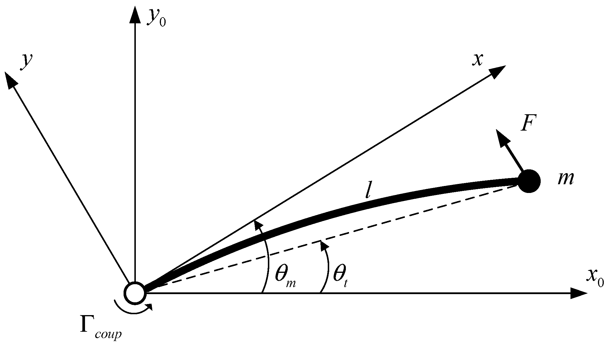
2. Modeling of Single-Link Flexible Arm

In this section, the model of the flexible arm is carried out by using the lumped mass method. Firstly, we assume that the single-link flexible arm moves in the horizontal plane so that gravity can be ignored. Secondly, we assume that the weight of the link is light enough and the weight of the payload mass is several times that of the link. Simultaneously, the payload mass is concentrated enough that its inertia can be ignored. In addition, we assume that some external forces are applied to the robotic arm. Based on the above considerations, and according to Figure 1, the dynamics of the link can be expressed as follows:
c ( θ m θ t ) = m l 2 θ ¨ t + F l
where θ m and θ t denote the motor gearbox angle and the angle of the tip mass, respectively, l is the length of the arm, F is the y-axis component of the resultant force exerted on the tip, and c is the stiffness of the link.
The single-link flexible arm is driven by a dc motor through a reduction mechanism. The dynamic model of the motor can be obtained by using Newton’s second law:
Γ ^ m = k V = J θ ^ ¨ m + v θ ^ ˙ m + Γ ^ c ( θ ^ ˙ m , V ) + Γ c o u p n
where Γ ^ m represents the motor torque, θ ^ m is the angular of the motor, n is the reduction ratio of the gear, Γ c o u p is the coupling torque exerted on the output of the gearbox due to deflection of the link, J , v , and k are the motor inertia, the viscous friction of the motor, and the motor constant, respectively, k is equal to the product of the electromechanical constant and the amplifier gain, V is the control voltage of the motor calculated by the computer, Γ ^ c is the Coulomb friction, and v is the viscous damping coefficient of the motor. The relationship between the rotation angle of the motor and the rotation angle of the gearbox is as follows:
θ ^ m = θ m n
The coupling torque between the gearbox and the link is given by:
Γ c o u p = c ( θ m θ t )
Non-linear friction is considered as Coulomb friction, which only changes with the sign of the motor angular velocity.
{ Γ ^ c = Γ ^ c o u l sign ( θ ^ ˙ m ) for θ ^ ˙ m 0 Γ ^ c = min ( | k V Γ ^ c o u p n | , Γ ^ c o u l ) sign ( k V Γ ^ c o u p n ) for θ ^ ˙ m = 0
where Γ ^ c o u l is the static friction value.
By sorting out Equation (1), the following dynamic model can be obtained:
θ ¨ t = ω 0 2 ( θ m θ t ) + ω 0 2 d
where ω 0 = c m l 2 is the natural frequency of the link and d = F l c . Equations (2), (3) and (6) are the dynamic model of a single-link flexible arm driven by a DC motor with the tip external force disturbance.

3. General Control Scheme

The controller design of the flexible manipulator focuses on two tasks: accurate positioning of the hub and suppression of tip vibration. In order to simplify the controller design process, decoupling is usually performed, that is, the two closed-loop control loops including an inner loop and outer loop are used to complete the above two tasks respectively. The inner loop is used to realize the servo control of the motor, and the outer loop is used to suppress the tip vibration to achieve the purpose of precise tip positioning. The features of this control structure are described in [2,32]. If the closed-loop bandwidth of the inner loop is much greater than the bandwidth of Equation (6) and the coupling torque is effectively suppressed, the outer loop controller can be designed independently because the dynamics of the outer loop plant can be approximated as Equation (6). The overall structure of the control system is shown in Figure 2, and its details will be introduced in the following two subsections.

3.1. Inner Loop Controller

The coupling torque between the gear and the flexible link can be decoupled by the following formula:
V = V c + Γ c o u p k n
After applying torque compensation, Equation (2) can be given by:
θ ^ ¨ m = k V c v θ ^ ˙ m + Γ ^ c ( θ ^ ˙ m , u ) J
The coupling torque can be measured by a strain gauge installed at the bottom end of the link. If the influence of friction can be suppressed by the compensation term [33] and a sufficiently high closed-loop bandwidth can be ensured, the purpose of decoupling the inner and outer loops can be achieved. On the one hand, considering the simplicity of the control algorithm, a simple PD controller is used to modify the dynamics of the DC motor.
V c = k m 1 * e ^ m + k m 2 * e ^ ˙ m
where e ^ m = θ ^ m θ ^ m and k m 1 * and k m 2 * are the proportional gain and differential gain, respectively. In order to facilitate parameter tuning, the damping term of the DC motor is compensated and the two poles are placed at the same point of the real line s = a m , then the new control law can be rewritten as:
V c = 1 b m ( k m 1 e ^ m + k m 2 e ^ ˙ m ) + v θ ^ ˙ m k
where b m = k J , k m 1 = a m 2 , and k m 2 = 2 a m . If the Coulomb friction Γ ^ c ( θ ^ ˙ m , u ) is ignored, then from Equations (8) and (10), we have θ ^ ¨ m = k m 1 e ^ m + k m 2 e ^ ˙ m . Using e ^ m = θ ^ m θ ^ m and performing the Laplace transform, we get:
G I n n e r   l o o p = θ ^ m ( s ) θ ^ m * ( s ) = k m 2 s + k m 1 s 2 + k m 2 s + k m 1 = 2 a m s + a m 2 ( s + a m ) 2
Obviously, if a m ω 0 , the dynamics of the outer loop can be approximated by Equation (6).

3.2. Outer Loop Controller

The function of the outer loop controller is to suppress the tip vibration and accurately track the desired trajectory. In addition, the outer loop should have two important properties: (a) it is robust enough to changes in the tip payload, and furthermore, it can overcome the changes in inner loop parameters; (b) its disturbance suppression capability can cope with the residual control error of the inner loop and the external torque disturbance. The outer loop controller is usually designed as a PID type controller, which has robustness to the model uncertainties. However, PID-type methods are limited in disturbance (especially nonlinear time-varying disturbance) suppression. In addition, in order to obtain the desired property, the controllers in the above literature usually use the natural frequency of the arm, which is related to the size of the tip mass, in parameter tuning. Therefore, the closed-loop system cannot reach the expected design goal with the payload variations.
In this section, an outer loop control strategy based on a robust ADRC is developed to accomplish the above two tasks and overcome the defects of existing PID-type control methods.

3.2.1. Extended State Observer

Let x 1 = θ t , x ˙ 1 = x 2 , then Equation (6) can be rewritten as a state space expression:
x ˙ 1 = x 2 x ˙ 2 = ω 0 2 x 1 + ω 0 2 d + b u
where b = ω 0 2 is the control gain and u = θ m . Consider that the value of b depends on the size of the tip payload, b is not a definite constant for the changing payload. The traditional method is to take its nominal value b ^ to design the controller. Let f ( t ) = ω 0 2 x 1 + ω 0 2 d + b ˜ u , where b ˜ = b b ^ denotes the total disturbance including the modeling error and external disturbance, we have:
x ˙ 1 = x 2 x ˙ 2 = f ( t ) + b ^ u
Note the existence of the term b ˜ u in f , so even if the system states and external disturbance are zero, b ˜ u 0 still means f 0 .
Using x 3 to represent the total disturbance f , the extended model of Equation (13) can be given by the following equation:
x ˙ 1 = x 2 x ˙ 2 = x 3 + b ^ u x ˙ 3 = h ( t )
where h = f ˙ . In order to reconstruct the total disturbance x 3 , ESO is usually applied refs. [34,35,36], and the conventional linear ESO can be given by the following form:
ε 1 = x 1 z 1 z ˙ 1 = z 2 + β 1 ε 1 z ˙ 2 = z 3 + β 2 ε 1 + b ^ u z ˙ 3 = β 3 ε 1
where b ^ is the nominal value of b . From Equations (14) and (15), we can get the estimation error system with the following compact form:
ε ˙ = A ε + B h h ( t )
where ε = [ ε 1 , ε 2 , ε 3 ] T , A = [ β 1 1 0 β 2 0 1 β 3 0 0 ] and B h = [ 0 , 0 , 1 ] T . β i , i = 1 , 2 , 3 are set such that A is Hurwitz with desired eigenvalues. A parameter tuning method is proposed by [17] with which the three parameters β i , i = 1 , 2 , 3 are reduced into one ω o b , the observer bandwidth. ε shows asymptotic convergence to zero yields h ( t ) = 0 . However, if h ( t ) 0 , the estimation error is inevitable [37].
Lemma 1.
If h ( t ) is bounded, then there exist two constants γ > 0 , α > 0 , and a finite time T 0 > 0 such that the trajectories of Equation (16) are bounded and the following inequality holds:
ε ( t ) γ e α ( t t 0 ) ε ( t 0 ) + γ α sup t 0 τ t h ( τ )
for t > T 0 > 0 , where t 0 is the initial time.
Proof of Lemma 1.
Integrating Equation (16), we have:
ε ( t ) = e A ( t t 0 ) ε ( t 0 ) + t 0 t e A ( t τ ) h ( τ ) d τ
It is easy to check that for the large enough constants γ > 0 , α > 0 , one has e A ( t t 0 ) γ e α ( t t 0 ) , and then an estimate of Equation (18) is shown as follows:
ε ( t ) γ e α ( t t 0 ) ε ( t 0 ) + t 0 t γ e α ( t t 0 ) h ( τ ) d τ γ e α ( t t 0 ) ε ( t 0 ) + γ α sup t 0 τ t h ( τ )
 □

3.2.2. Feedback Control Law

Based on the above ESO, a PD-type controller is usually applied:
u = k 1 ( r 1 z 1 ) + k 2 ( r 2 z 2 ) f ^ b ^ = u 0 f ^ b ^
where r 1 is the reference input, r 2 = r ˙ 1 , and f ^ = z 3 . Based on control law Equation (20), Equation (13) can be rewritten as follows:
x ˙ 1 = x 2 x ˙ 2 = f f ^ + u 0
If f ^ can asymptotically converge to f , we can make x asymptotically stabilize at the origin by the proper choice of k i ( i = 1 , 2 ) . The bandwidth tuning method in [17] is a good choice, by which k i ( i = 1 , 2 ) is simplified to one parameter ω c . However, the total disturbance f of the flexible manipulator model (13) is always time-varying in the actual operation, that is h ( t ) 0 , so there is always an error between f ^ and f . The time-varying property of the total disturbance f mainly comes from the time-varying external disturbance and b ˜ u . Moreover, the time-varying characteristics of b ˜ u may be caused by two reasons: one is the changing reference input; the other is a tip payload that alters in real time. Therefore, the PD-type control law cannot meet the requirements of robustness and disturbance suppression for flexible manipulators with varying tip payloads.
Based on the above considerations, a sliding mode term is added to the control law Equation (20) to surmount the loss of disturbance rejection and robustness as a result of the inability to fully compensate for the total disturbance f :
u = u 0 z 3 + u S M b ^ u S M = κ s i g n ( s ) s = e 1 + η e 2
where e 1 = x 1 r 1 , e 2 = e ˙ 1 = x 2 r 2 , and η > 0 is a well-chosen constant.
It is easy to check that the maximum error between f and its estimate f ^ is bounded by Lemma 1. Furthermore, if the system goes into the steady state, the estimation error will be zero. Moreover, given that f ^ is differentiable, we make the following assumption.
Assumption 1.
It is assumed that there is a sufficiently large constant λ 1 > 0 such that the maximum error between f and f ^ fulfills the following inequality:
| f ¯ | = | f f ^ | λ 1 | f ^ ˙ |
On the premise of Assumption 1, the following theorem can be developed.
Theorem 1.
For the flexible arm Equation (12), the feedback control law Equation (22) can force the system states to slide on the SMsurface s = 0 , for each value of the estimation error f ¯ satisfying Assumption 1, if the gain κ is devised in the following form:
κ = λ 1 | f ^ ˙ | + | u 0 | + | η e 2 r ˙ 2 |
Proof of Theorem 1.
Define a Lyapunov function:
V ( s ) = 1 2 s 2
Let V ˙ < 0 to get stability in the Lyapunov sense:
{ s ˙ < 0 ,    f o r   s > 0 s ˙ > 0 ,    f o r   s < 0
The derivative of s is given by:
s ˙ = x ˙ 2 r ˙ 2 + η e 2 = f ¯ + u 0 κ s i g n ( s ) r ˙ 2 + η e 2
Substituting Equation (27) into Equation (26), we can see that κ needs to satisfy the following inequality:
κ > max f ¯ | f ¯ + u 0 r ˙ 2 + η e 2 |
Using Assumption 1, we have:
| f ¯ + u 0 r ˙ 2 + η e 2 | | f ¯ | + | u 0 | + | r ˙ 2 + η e 2 | λ 1 | f ^ ˙ | + | u 0 | + | r ˙ 2 + η e 2 |
From Equation (29), it follows that Equation (26) is satisfied if Equation (24) holds. □
Theorem 1 is interesting in that, when the estimation error f ¯ satisfies Equation (23), it provides a strict way to design a robust control law to solve the problem mentioned at the beginning of this section, where f ¯ of time-varying total disturbance brings about damage in robustness and disturbance suppression.
Remark 1.
The proof of Theorem 1 can be divided into two procedures. The first part is to estimate the upper bound of the gain κ satisfying the sliding condition as in [37]; the second part is to select a time-varying κ by considering the current states, estimates, and measurements. The first option is too conservative to increase chattering in the system. Hence, the second one is adopted in this paper.
Remark 2.
Indeed, we could also assume that the maximum error between f and its estimate f ^ satisfies the following inequality:
| f ¯ | λ 2 | f ^ |
where λ 2 > 0 is a constant. Using Equation (30), we can get another time-varying gain κ :
κ = λ 2 | f ^ | + | u 0 | + | η e 2 r ˙ 2 |
Compared with Equation (24), Equation (31) is also conservative because f ^ 0 yielding to f 0 when the system enters a steady state and the reference input is constant. In this case, κ in Equation (31) will become a constant greater than zero, which is equivalent to the first part in Remark 1. However, under the steady-state condition, κ in Equation (24) will converge to zero, and the robust control law Equation (22) will degenerate into a nominal control law Equation (20), which can effectively avoid chattering. Moreover, it is worth mentioning that although κ in Equation (24) is time-varying, it does not depend on the unknown parameter b or the unmeasurable disturbance f , but it only considers utilizing f ^ ˙ to estimate the maximum upper bound of the error f ¯ .

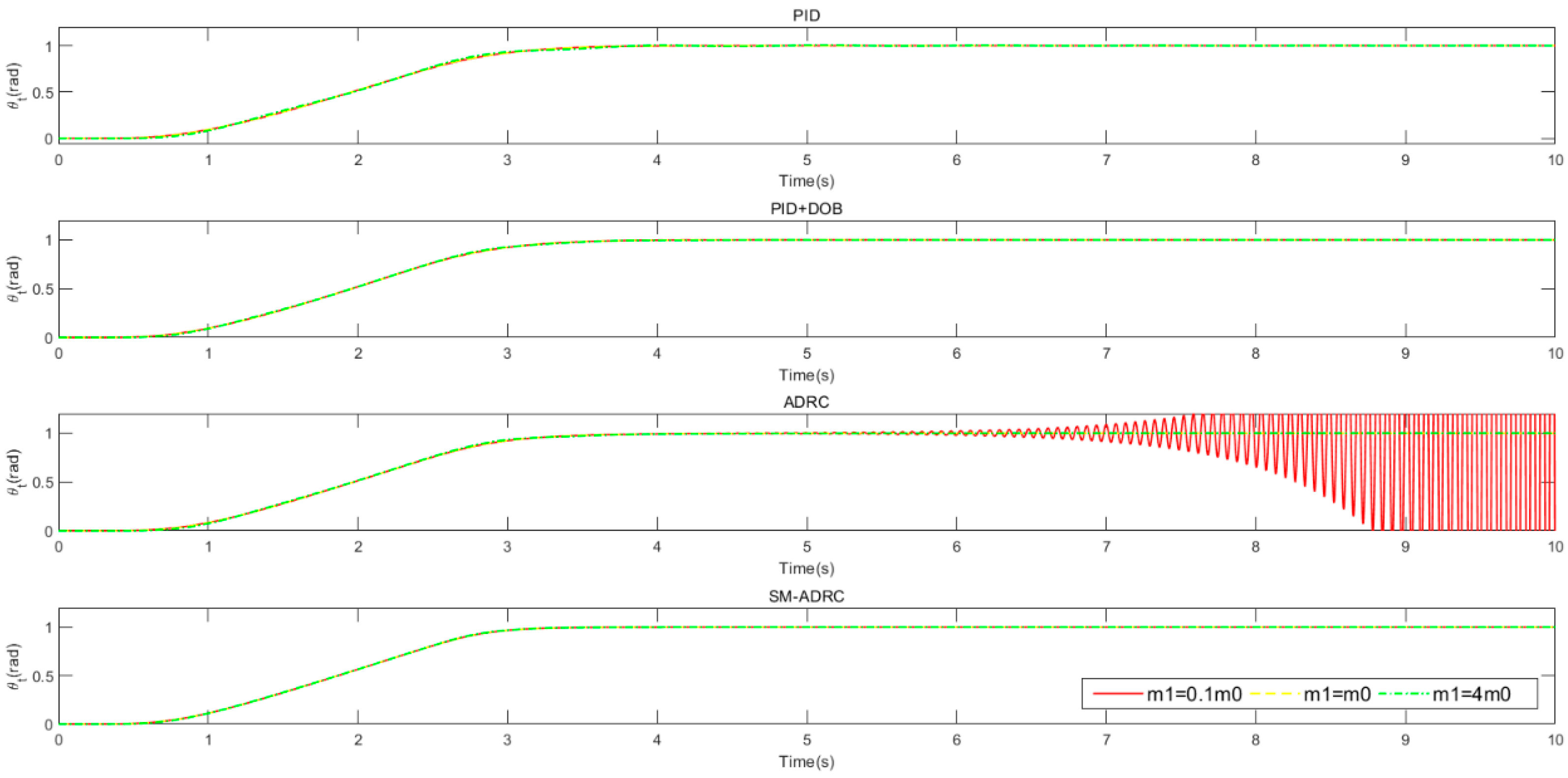
4. Simulation Results

In this section, we will demonstrate the effectiveness of the developed method by showing some numerical simulations. The numerical simulations are realized by Simulink of MATALAB. The relevant parameters of the flexible manipulator and motor are given in Table 1, and the control parameters are shown in Table 2. The parameters are all from [3].

4.1. Simulation Results with m 1 = m 0

In this section, the tracking performance of the proposed method is verified and compared with ADRC, PID, and PID+DOB (Disturbance observer) methods. The parameter tuning method of PID is similar to the bandwidth tuning method in [3], but in order to reduce the rise time of step response and improve the disturbance rejection ability, the integral gain is appropriately amplified. The parameters of the PID controller are k p = 3 ω c 2 ω 0 2 = 1.3 , k I = 2.74 ω c 3 ω 0 2 = 6.02 , and k d = 3 ω c ω 0 2 = 0.26 . The nominal model of DOB is as follows:
p n = ω 0 2 s 2 + ω 0 2
The simulation results of tracking trajectory of the tip position and tracking error e θ t = θ t * θ t are shown in Figure 3. Compared with the other three methods, the proposed method (SM-ADRC) has a faster response speed, and thus, a smaller tracking error both in forward and backward direction. In addition, considering that the flexible manipulator may be impacted in the process of motion, a perturbation is added at t = 6 s, which is a pulse signal used to simulate the impact disturbance in the actual work. Its amplitude is 1deg, and the pulse width time is 0.1 s. It can be seen from the figure that SM-ADRC can compensate torque perturbation more quickly. This result is clearly shown in Table 3 by calculating the index integral absolute error (IAE) during the whole tests and within 6–7 s, respectively. The data in Table 3 show that the tracking accuracy and the suppression impact disturbance performance of the proposed method are significantly improved.
Considering that the flexible manipulator may be affected by time-varying disturbances such as wind force and base movement during outdoor operation, a sinusoidal ( 0.1 sin ( π ) ) torque disturbance is added to the simulation, and the simulation results are shown in Figure 4. Under the same disturbance, SM-ADRC has a smaller tracking error. The maximum tracking errors of the four methods are PID: 0.041 rad, PID+DOB: 0.021 rad, ADRC: 0.028 rad, and SM-ADRC: 0.010 rad. Therefore, compared with the remaining three methods, the disturbance inhibition ability of the proposed method has increased by at least double.

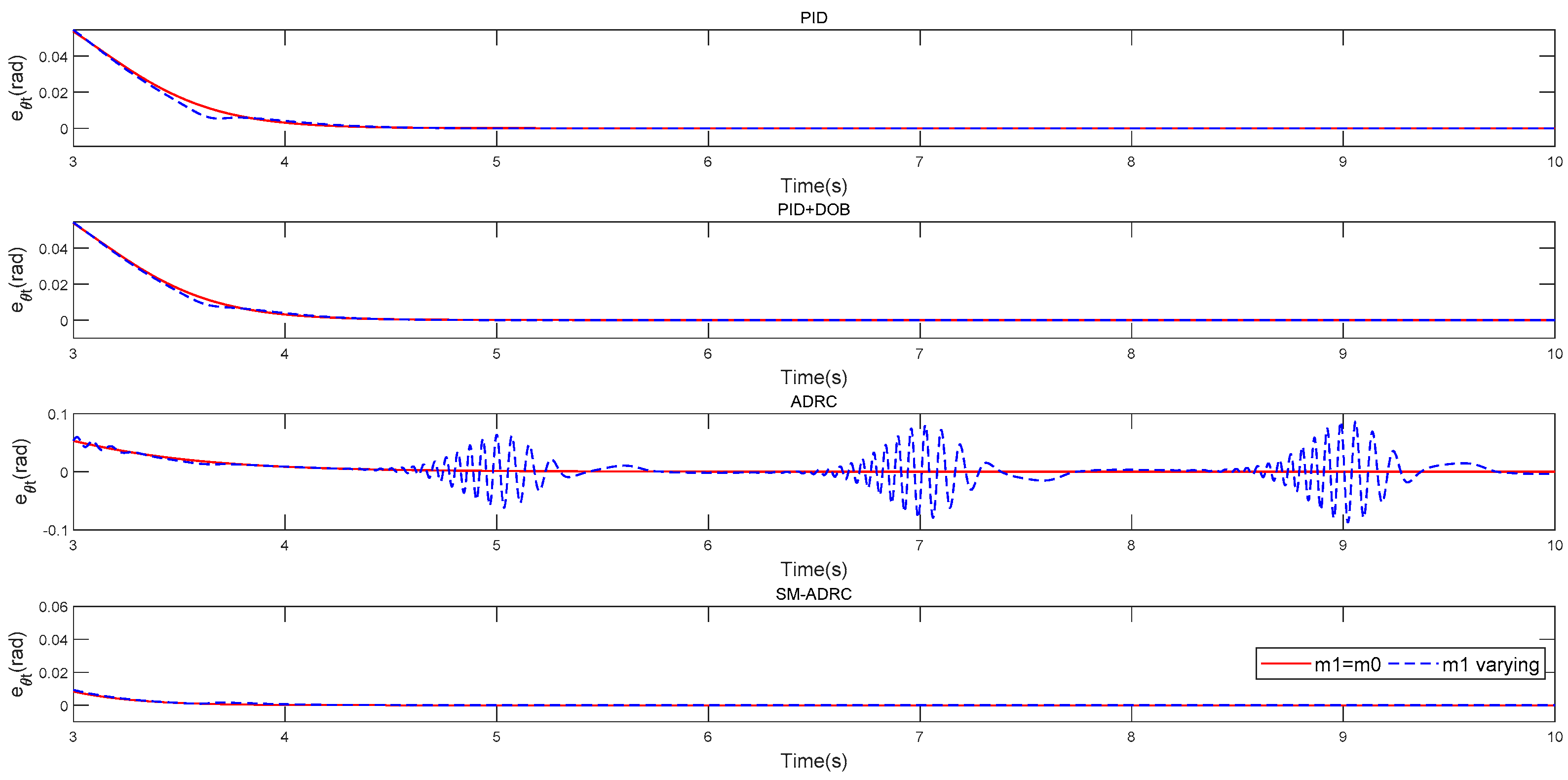
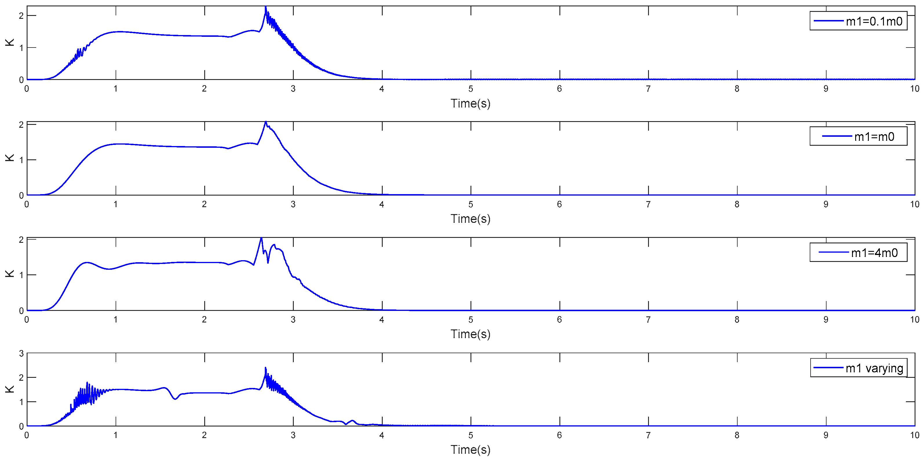
4.2. Robustness Test

This section mainly tests the robustness of the proposed controller by considering the possible effects if the system contains unmodeled dynamic behavior caused by mass varying at the tip. Firstly, the tip mass is changed from the nominal mass m 0 to 0.1 m 0 and 4 m 0 , respectively, and the simulation results are shown in Figure 5 and Figure 6. As analyzed in Section 3, the lack of prior knowledge of the control gain b will lead to the reduction of the robustness of ADRC, so ADRC loses stability at m 1 = 0.1 m 0 (where b = 10 b ^ ). The deficit of robustness owing to the uncertainty of the model can be compensated by adding SM component given by Equations (22) and (24). Furthermore, the proposed SM-ADRC method is the most robust among the four control methods, both in terms of stability and tracking performance, because its tracking accuracy is the highest and the tracking trajectory is almost unchanged with the tip mass varying.
Moreover, in order to further verify the robustness advantage of the proposed method, we carried out simulation with the time-varying tip mass, as shown in Figure 7 and Figure 8. The tip mass m 1 varies within the range of [ 0.1 m 0 , 18 m 0 ] . From the simulation results, we can see that ADRC has obvious oscillation phenomenon when the tip mass varies, while the other three methods maintain stable tracking trajectory. It is worth emphasizing that under the above simulation conditions, SM-ADRC is always stable and has the highest tracking accuracy. Therefore, the proposed method is more robust in dealing with load weight change. In addition, in Figure 9, we show the variation curves of SM gain under several different conditions in the robustness test. The results show that when the system tends to steady state, the proposed sliding gain Equation (29) converge to near zero, which can effectively avoid the occurrence of chattering.

5. Conclusions

In this paper, a novel robust control scheme for a lightweight flexible single-link manipulator is proposed, which is composed of an inner loop and an outer loop. The inner loop adopts the traditional PD control, and an active disturbance rejection control (ADRC) with sliding mode (SM) compensation is designed in the outer loop. The SM compensation is mainly used to deal with the loss of disturbance suppression ability and robustness caused by the disturbance observation error of the extended state observer (ESO). The main contribution of the proposed control method is that the sliding gain of the SM component is adapted to the disturbance estimation, which reduces the chattering while improving the system robustness. According to the simulation results, the following conclusions can be obtained: (a) the proposed SM compensation method can effectively overcome the defects of traditional ADRC; (b) the proposed SM component is superior in suppressing chattering; (c) compared to PID, PID+DOB, and ADRC, the proposed method is excellent in terms of tracking accuracy, disturbance rejection, and robustness. Our future research will apply this method to practical platforms.

Author Contributions

Conceptualization, F.W., P.L. and F.J.; methodology, F.W.; software, F.W.; validation, F.W.; formal analysis, F.W.; investigation, F.W.; resources, B.L.; data curation, F.W.; writing—original draft preparation, F.W.; writing—review and editing, F.W.; visualization, F.W.; supervision, M.G.; project administration, W.P.; funding acquisition, M.X. All authors have read and agreed to the published version of the manuscript.

Funding

This research received no external funding.

Institutional Review Board Statement

Not applicable.

Informed Consent Statement

Not applicable.

Data Availability Statement

Not applicable.

Acknowledgments

Our thanks to Tianji Cheng for his help in the method design and suggestions on paper writing.

Conflicts of Interest

The authors declare no conflict of interest.

References

  1. Feliu, V.; Ramos, F. Strain gauge based control of single-link flexible very lightweight robots robust to payload changes. Mechatronics 2005, 15, 547–571. [Google Scholar] [CrossRef]
  2. Feliu, V.; Castillo, F.J.; Ramos, F.; Somolinos, J.A. Robust tip trajectory tracking of a very lightweight single-link flexible arm in presence of large payload changes. Mechatronics 2012, 22, 594–613. [Google Scholar] [CrossRef]
  3. Morales, R.; Feliu, V.; Jaramillo, V. Position control of very lightweight single-link flexible arms with large payload variations by using disturbance observers. Robot. Auton. Syst. 2012, 60, 532–547. [Google Scholar] [CrossRef]
  4. Feliu-Talegon, D.; Feliu-Batlle, V. Passivity-based control of a single-link flexible manipulator using fractional controllers. Nonlinear Dyn. 2019, 95, 2415–2441. [Google Scholar] [CrossRef]
  5. Yang, J.H.; Lian, F.L.; Fu, L.C. Nonlinear adaptive control for flexible-link manipulators. IEEE Trans. Robot Autom. 1997, 13, 140–148. [Google Scholar] [CrossRef]
  6. Becedas, J.; Trapero, J.R.; Feliu, V.; Sira-Ramírez, H. Adaptive controller for single-link flexible manipulators based on algebraic identification and generalized proportional integral control. IEEE Trans. Syst. Man Cybern. Part B Cybern. 2009, 39, 735–751. [Google Scholar] [CrossRef]
  7. Corradini, M.L.; Giantomassi, A.; Ippoliti, G.; Longhi, S.; Orlando, G. Robust control of robot arms via quasi sliding modes and neural networks. Stud. Comput. Intell. 2015, 576, 79–105. [Google Scholar]
  8. Sun, C.; Wei, H.; Jie, H. Neural network control of a flexible robotic manipulator using the lumped spring-mass model. IEEE Trans. Syst. Man Cybern. Syst. 2017, 47, 1863–1874. [Google Scholar] [CrossRef]
  9. Zhang, H.; Gao, X.; Xu, G. Research on improved PD control of flexible manipulator. In Proceedings of the 2019 Chinese Control and Decision Conference, Nanchang, China, 3–5 June 2019. [Google Scholar]
  10. Sayahkarajy, M.; Mohamed, Z.; Faudzi, A.; Supriyanto, E. Hybrid vibration and rest-to-rest control of a two-link flexible robotic arm using H∞ loop-shaping control design. Forum. Math. 2016, 18, 171–191. [Google Scholar] [CrossRef]
  11. Zhang, L.; Li, X.; Liu, H.; Wang, A.; Cao, X. Backstepping-based H∞ tracking control for single-link flexible joint manipulators. In Proceedings of the 2019 Chinese Control Conference, Guangzhou, China, 27–30 July 2019. [Google Scholar]
  12. O’Connor, W.J.; de la Flor, F.R.; McKeown, D.J.; Feliu, V. Wave-based control of non-linear flexible mechanical systems. Nonlinear Dyn. 2009, 57, 113. [Google Scholar] [CrossRef]
  13. Pereira, E.; Aphale, S.S.; Feliu, V.; Moheimani, S.R. Integral resonant control for vibration damping and precise tip-positioning of a single-link flexible manipulator. IEEE/ASME Trans. Mechatron. 2010, 16, 232–240. [Google Scholar] [CrossRef] [Green Version]
  14. Han, J. Active disturbance rejection controller and its applications (in Chinese). Control Decis. 1998, 13, 19–23. [Google Scholar]
  15. Han, J. From PID to active disturbance rejection control. IEEE Trans. Ind. Electron. 2009, 56, 900–906. [Google Scholar] [CrossRef]
  16. Gao, Z. Scaling and bandwidth-parameterization based controller tuning. In Proceedings of the American Control Conference, Denver, CO, USA, 4–6 June 2003; Volume 6, pp. 4989–4996. [Google Scholar]
  17. Yang, H.; Yang, Y.; Yuan, Y.; Fan, X. Back-stepping control of two-link flexible manipulator based on an extended state observer. Adv. Space Res. 2015, 56, 2312–2322. [Google Scholar] [CrossRef]
  18. Fareh, R. Control of a single flexible link manipulator using fractional active disturbance rejection control. In Proceedings of the 6th International Conference on Control, Decision and Information Technologies, Paris, France, 23–26 April 2019. [Google Scholar]
  19. Li, R.; Li, T.; Bu, R.; Zheng, Q.; Chen, C. Active disturbance rejection with sliding mode control based course and path following for underactuated ships. Math. Probl. Eng. 2013, 2013. [Google Scholar] [CrossRef]
  20. Chen, C.F.; Du, Z.J.; He, L.; Wang, J.; Wu, D.; Dong, W. Active disturbance rejection with fast terminal sliding mode control for a lower limb exoskeleton in swing phase. IEEE Access 2019, 7, 72343–72357. [Google Scholar] [CrossRef]
  21. Karami, M.; Kazemi, A.; Vatankhah, R.; Khosravifard, A. Adaptive fractional-order backstepping sliding mode controller design for an electrostatically actuated size-dependent microplate. J. Vib. Control. 2021, 27, 1353–1369. [Google Scholar] [CrossRef]
  22. Tuwa, P.R.N.; Woafo, P. Suppression of the noise-induced effects in an electrostatic micro-plate using an adaptive back-stepping sliding mode control. ISA Trans. 2018, 72, 100–109. [Google Scholar] [CrossRef]
  23. Takougang, S.; Kingni, A.; Cheukem, P.R.; Nwagoum Tuwa, A.C.; Chamgoué, V.; Pham, T.; Jafari, S. Synchronous reluctance motor with load vibration perturbation: Analysis, electronic implementation and adaptive backstepping sliding mode control. Iran. J. Sci. Technol. Trans. Electr. Eng. 2021, 45, 645–654. [Google Scholar]
  24. Faraji, B.; Gheisarnejad, M.; Yalsavar, M.; Khooban, M.H. An adaptive ADRC control for parkinson’s patients using machine learning. IEEE Sens. J. 2020, 21, 8670–8678. [Google Scholar] [CrossRef]
  25. Liu, W.; Zhao, T. An active disturbance rejection control for hysteresis compensation based on Neural Networks adaptive control. ISA Trans. 2021, 109, 81–88. [Google Scholar] [CrossRef]
  26. Wu, D.; Ren, F.; Qiao, L.; Zhang, W. Active disturbance rejection controller design for dynamically positioned vessels based on adaptive hybrid biogeography-based optimization and differential evolution. ISA Trans. 2018, 78, 56–65. [Google Scholar] [CrossRef]
  27. Qiao, H.; Meng, H.; Ke, W.; Gao, Q.; Wang, S. Adaptive control of missile attitude based on BP–ADRC. Aircr. Eng. Aerosp. Technol. 2020, 92, 1475–1481. [Google Scholar] [CrossRef]
  28. Du, C.; Yin, Z.; Zhang, Y.; Liu, J.; Sun, X.; Zhong, Y. Research on active disturbance rejection control with parameter autotune mechanism for induction motors based on adaptive particle swarm optimization algorithm with dynamic inertia weight. IEEE Trans. Power Electron. 2018, 34, 2841–2855. [Google Scholar] [CrossRef]
  29. Yang, Z.; Wang, Z.; Yan, M. An Optimization design of adaptive cruise control system based on MPC. and ADRC. Actuators 2021, 10, 110. [Google Scholar] [CrossRef]
  30. Nie, Z.; Zhang, B.; Wang, Q.; Liu, R.; Luo, J. Adaptive active disturbance rejection control guaranteeing uniformly ultimate boundedness and simplicity. Int. J. Robust Nonlinear Control. 2020, 30, 7278–7294. [Google Scholar] [CrossRef]
  31. Feliu, V.; Rattan, K.S.; Brown, H.B. Adaptive control of a single-link flexible manipulator. IEEE Control Syst. Mag. 1990, 10, 29–33. [Google Scholar] [CrossRef]
  32. Feliu, V.; Rattan, K.S.; Brown, H.B. Control of flexible arms with friction in the joints. IEEE Trans. Robot. Autom. 1993, 9, 467–475. [Google Scholar] [CrossRef]
  33. Rosas Almeida, D.I.; Alvarez, J.; Cantu Cardenas, J.A. Application of the active disturbance rejection control structure to improve the controller performance of uncertain pneumatic actuators. Asian J. Control. 2019, 21, 99–113. [Google Scholar] [CrossRef] [Green Version]
  34. Gandhi, R.V.; Adhyaru, D.M. Hybrid extended state observer based control for systems with matched and mismatched disturbances. ISA Trans. 2020, 106, 61–73. [Google Scholar] [CrossRef]
  35. Liu, A.; Li, T.; Gu, Y.; Dai, H. Cooperative extended state observer based control of vehicle platoons with arbitrarily small time headway. Automatica 2021, 129, 109678. [Google Scholar] [CrossRef]
  36. Guo, B.Z.; Zhao, Z.L. On the convergence of an extended state observer for nonlinear systems with uncertainty. Syst. Control Lett. 2011, 60, 420–430. [Google Scholar] [CrossRef]
  37. Fareh, R.; Al-Shabi, M.; Bettayeb, M.; Ghommam, J. Robust active disturbance rejection control for flexible link manipulator. Robotica 2020, 38, 118–135. [Google Scholar] [CrossRef]
Figure 1. Diagram of a single-link flexible arm.
Electronics 10 02995 g001
Figure 2. General control scheme.
Electronics 10 02995 g002
Figure 3. Simulation results of tracking trajectory of the flexible manipulator tip position.
Electronics 10 02995 g003
Figure 4. Simulation results with sinusoidal torque disturbance.
Electronics 10 02995 g004
Figure 5. Tracking trajectories of the flexible manipulator tip position with different tip mass values.
Electronics 10 02995 g005
Figure 6. Tracking error trajectories of the flexible manipulator tip position with different tip mass values.
Electronics 10 02995 g006
Figure 7. Tracking trajectories of the flexible manipulator tip position with the tip mass varying.
Electronics 10 02995 g007
Figure 8. Tracking error trajectories of the flexible manipulator tip position with the tip mass varying.
Electronics 10 02995 g008
Figure 9. Gain κ of the SM term during the robustness test.
Electronics 10 02995 g009
Table 1. The parameters of the single-link flexible manipulator and DC motor.
DC Motor Parameters
Motor inertia J 6.87 × 10⁻⁵ (kg m2)
Viscous friction v 1.041 × 10⁻³ (N m s)
Electromechanical constant k 0.21 ((N m)/V)
Motor Coulomb friction torque Γ ^ c 119.7 × 10⁻³ (N m)
Flexible Manipulator Parameters
Nominal mass m 0 0.05 (kg)
Length L 0.7 (m)
Flexural rigidity E I 0.325 (N m2)
Stiffness c 1.395 (N m)
Nominal natural frequency ω 0 7.546 (rad/s)
Table 2. The control parameters.
Control Parameters
Location closed loop poles
(Inner loop)
a m 300
Controller bandwidth
(Outer loop)
ω c 5 (rad/s)
Observer bandwidth
(Outer loop)
ω o b 40 (rad/s)
Nominal control gain
(Outer loop)
b ^ 56.94
SM part Parameters η 5
λ 1 0.02
Sample time T s t 0.001
Table 3. Index integral absolute error.
Tracking ErrorPIDPID+DOBADRCSM-ADRC
0 15 | θ t θ t * | d t 338.7690335.5991385.8804119.9095
6 7 | θ t θ t * | d t 6.52933.49173.93361.4116
Publisher’s Note: MDPI stays neutral with regard to jurisdictional claims in published maps and institutional affiliations.

