
Optimal Hybrid PV Array Topologies to Maximize the Power Output by Reducing the Effect of Non-Uniform Operating Conditions

 , ,
, ,  , ,
, , 

Abstract
:1. Introduction
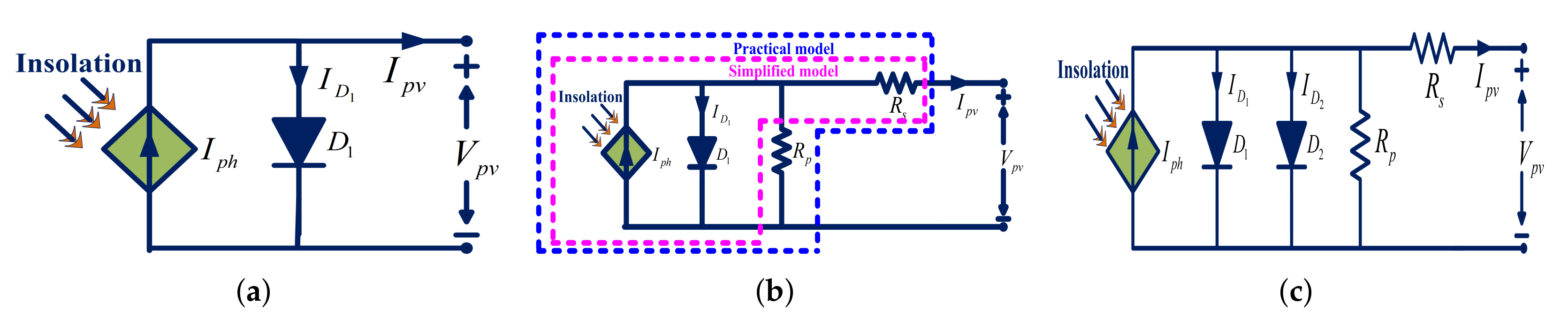
2. PV Module Two-Diode Model
- Equation (1) demonstrates the relation between output current and output voltage of a PV module:
- The diode reverse saturation currents, and are expressed by the Equation (3).
3. Conventional and Proposed Optimal Hybrid PV Array Topologies
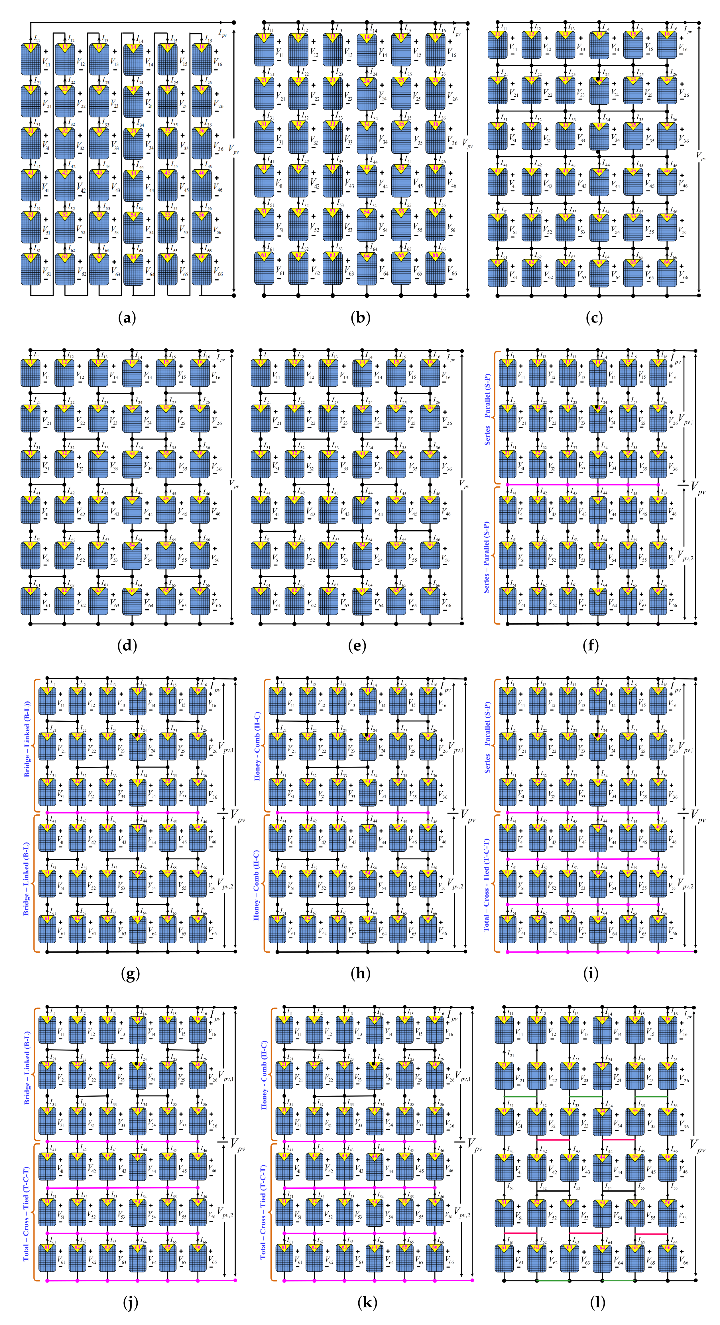
3.1. Conventional PV Array Topologies
3.1.1. Series-Parallel (S-P)
3.1.2. Total-Cross-Tied (T-C-T)
3.1.3. Bridge-Link (B-L)
3.1.4. Honey-Comb (H-C)
3.2. Hybrid PV Array Topologies
3.2.1. Series-Parallel-Cross-Tied (S-P-C-T)
3.2.2. Bridge-Link-Cross-Tied (B-L-C-T)
3.2.3. Honey-Comb-Cross-Tied (H-C-C-T)
3.2.4. Series-Parallel-Total-Cross-Tied (S-P-T-C-T)
3.2.5. Bridge-Link-Total-Cross-Tied (B-L-T-C-T)
3.2.6. Honey-Comb-Total-Cross-Tied (H-C-T-C-T)
3.2.7. Bridge-Link-Honey-Comb (B-L-H-C)
4. Modeling of Non-Uniform Operating Conditions
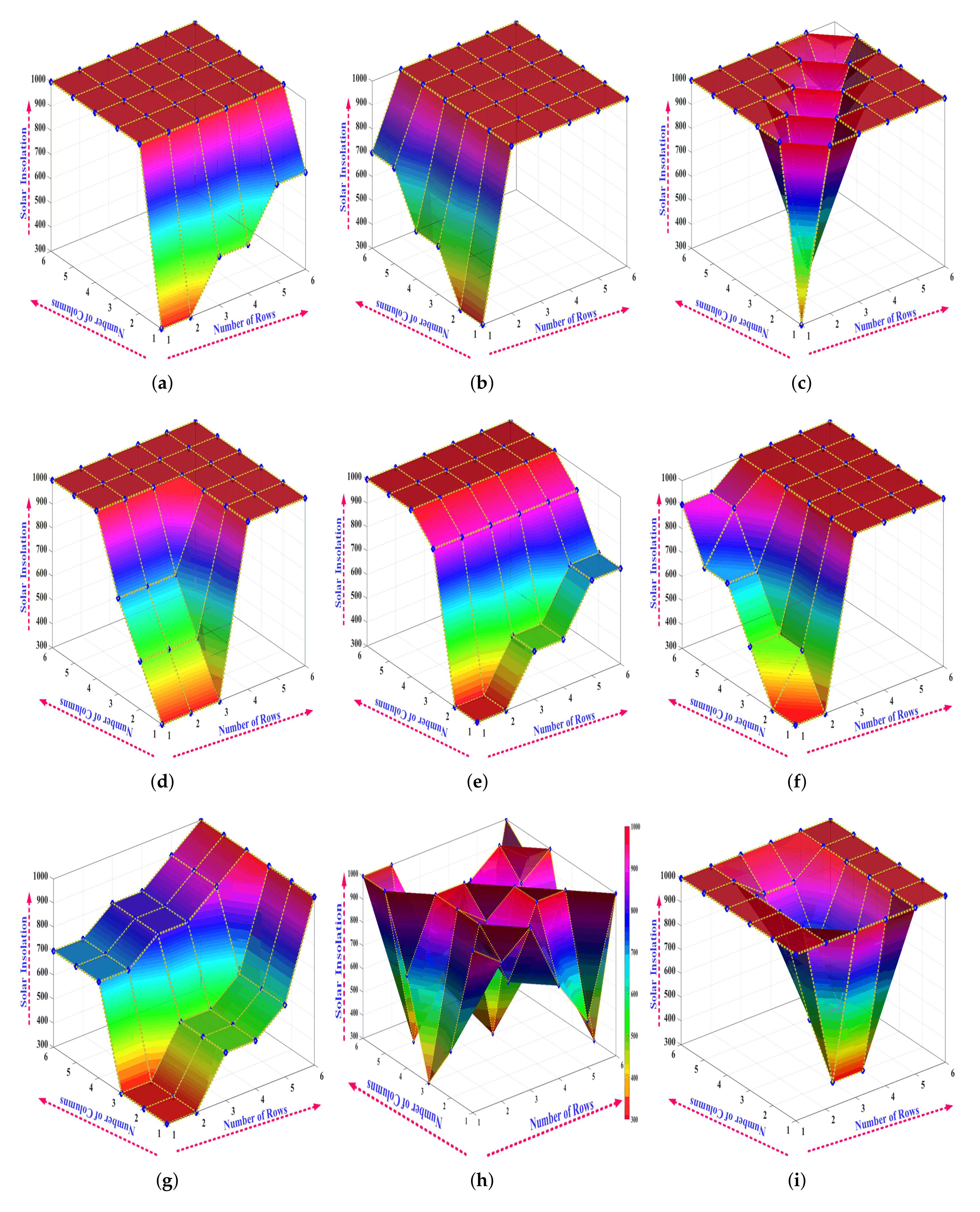
- Uneven-row: As shown in Figure 4a, the first row of array PV topologies is unevenly shaded with different insolation levels. The PV modules (11, 12), (13, 14) and (15, 16) receives an insolation of 300 W/m, 500 W/m and 700 W/m, respectively. The rest of all PV modules receives insolation of 1000 W/m.
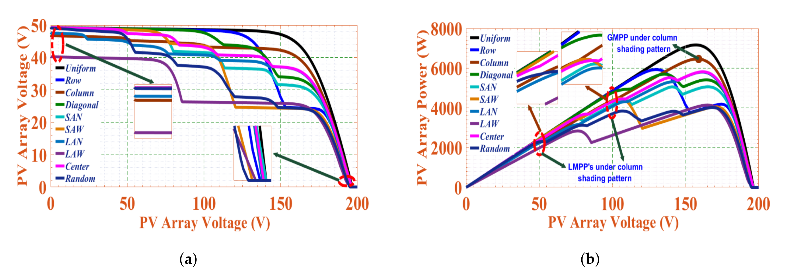
- Uneven-column: The first column of PV array topologies is unevenly shaded with different insolation levels, as shown in Figure 4b. The PV modules (11, 21), (31, 41), and (51, 61)receives an insolation of 300 W/m, 500 W/m and 700 W/m, respectively. The rest of all the PV modules receives insolation of 1000 W/m.
- Diagonal: The diagonally placed PV modules are shaded with different insolation levels, as shown in Figure 4c. The PV modules 11, 22, 33, 44, 55, and 66 receives an insolation of 300 W/m, 400 W/m, 500 W/m, 700 W/m, 800 W/m and 900 W/m, respectively. The rest of all the PV modules receives insolation of 1000 W/m.
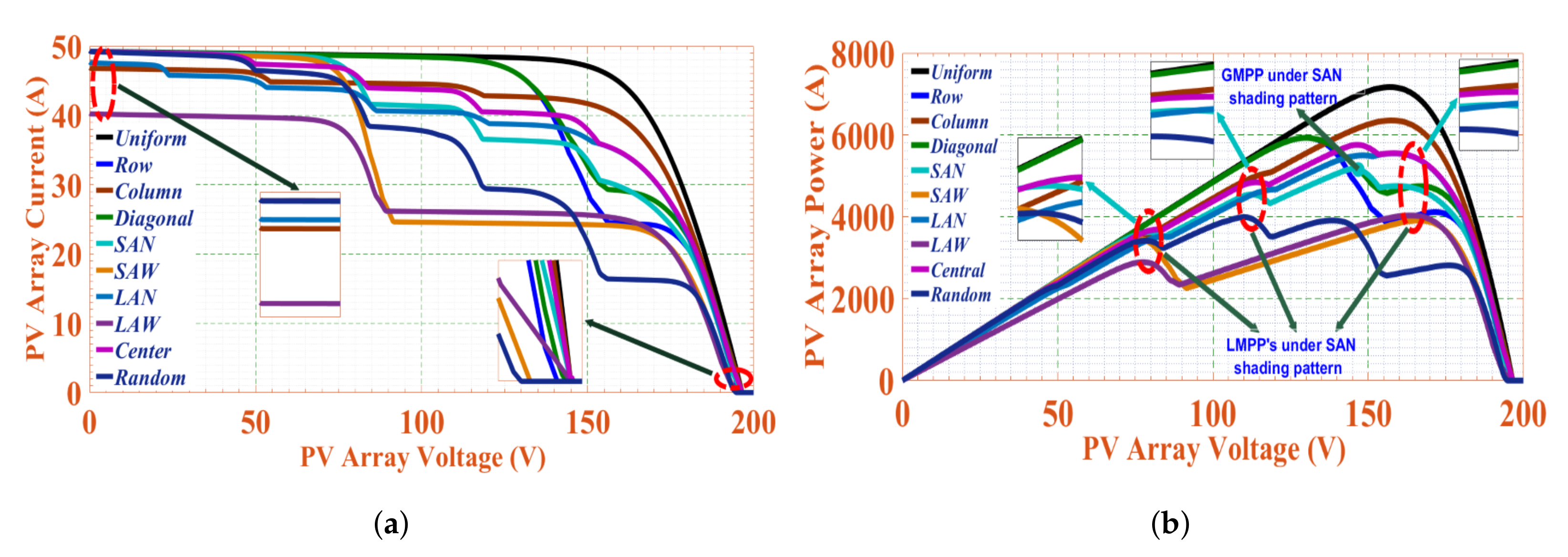
- Short and Narrow (SAN): As shown in Figure 4d, a fewer number of PV modules in the first three rows of array topologies are shaded with different insolation levels. The PV modules (11, 12, 13), (21,22, 23) and (31, 32, 33) receives an insolation of 300 W/m, 500 W/m and 700 W/m, respectively. The rest of all the PV modules receives insolation of 1000 W/m.
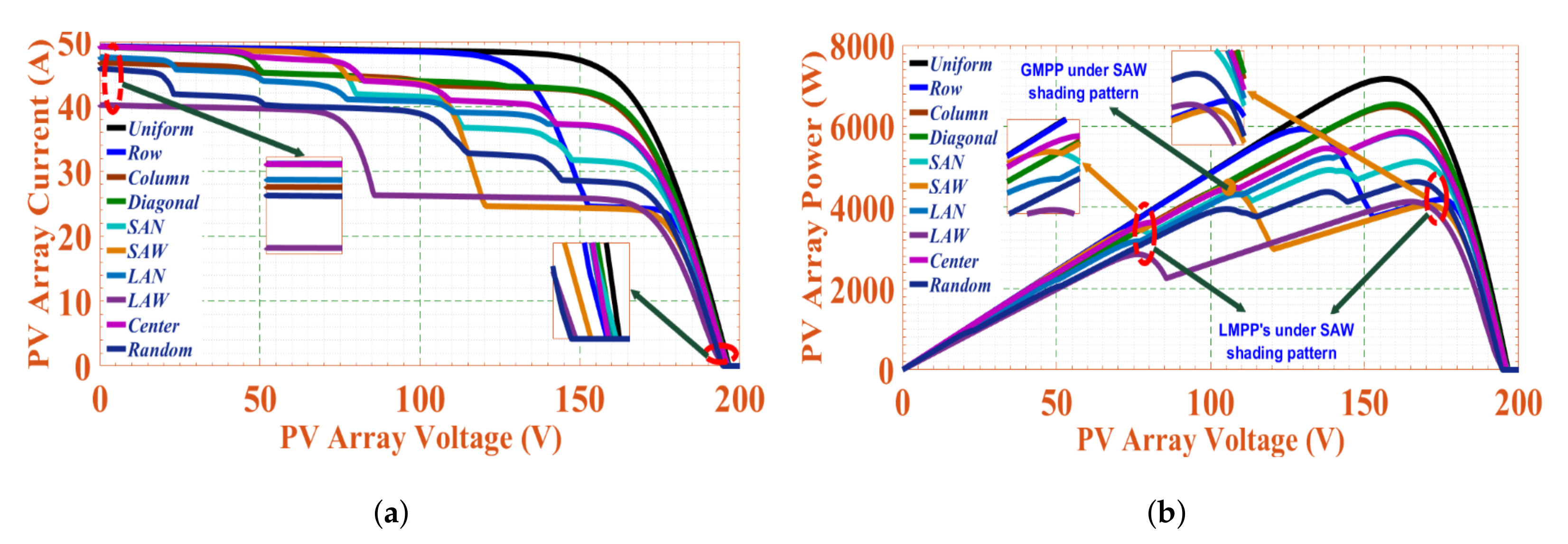
- Short and Wide (SAW): All the PV modules in the first three rows of array topologies are shaded with different insolation levels as shown in Figure 4e. The PV modules (11, 12, 21, 22), (13, 14, 23, 24), (15, 16, 25, 26) and (31, 32, 33, 34, 35, 36) receives an insolation of 300 W/m, 500 W/m, 700 W/m and 900 W/m, respectively. The rest of all the PV modules receives an insolation of 1000 W/m.
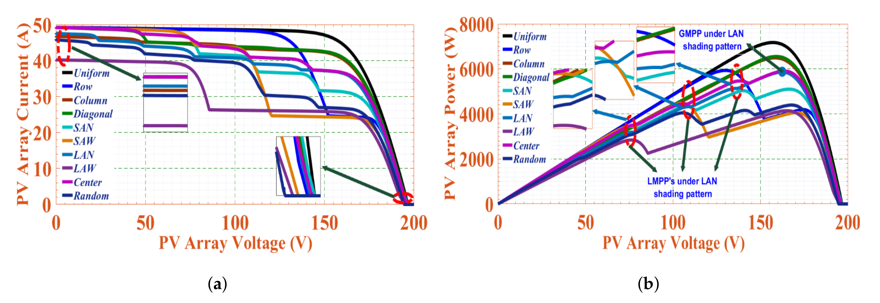
- Long and Narrow (LAN): The PV modules in the first two columns of array topologies are shaded with different insolation levels, as shown in Figure 4f. The PV modules (11, 12, 21), (22, 31, 32), (41, 42, 51) and (52, 61, 62) receives an insolation of 300 W/m, 500 W/m, 700 W/m and 900 W/m, respectively. The rest of all the PV modules receives insolation of 1000 W/m.
- Long and Wide (LAW): The PV modules in the first five columns of array topologies are shaded with different insolation levels as shown in Figure 4g. The PV modules (11, 12, 21, 22, 31, 32), (13, 14, 23, 24, 33, 34), (15, 25, 35), (41, 42, 51, 52, 61, 62), (43, 44, 54, 55, 64, 65) and (45, 55, 65) receives an insolation of 300 W/m, 500 W/m, 600 W/m, 700 W/m, 800 W/m and 900 W/m, respectively. The rest of all the PV modules receives an insolation of 1000 W/m.
- Random: As shown in Figure 4h, a fewer number of PV modules in all the six rows of array topologies are shaded with different insolation levels. The PV modules (26, 31, 44, 52, 65), (15, 21, 36, 53, 64), (14, 23, 35, 41, 63) and (12, 33, 45, 54, 56) receives an insolation level of 300 W/m, 500 W/m, 700 W/m and 900 W/m, respectively. The rest of all the PV modules receives an insolation of 1000 W/m.
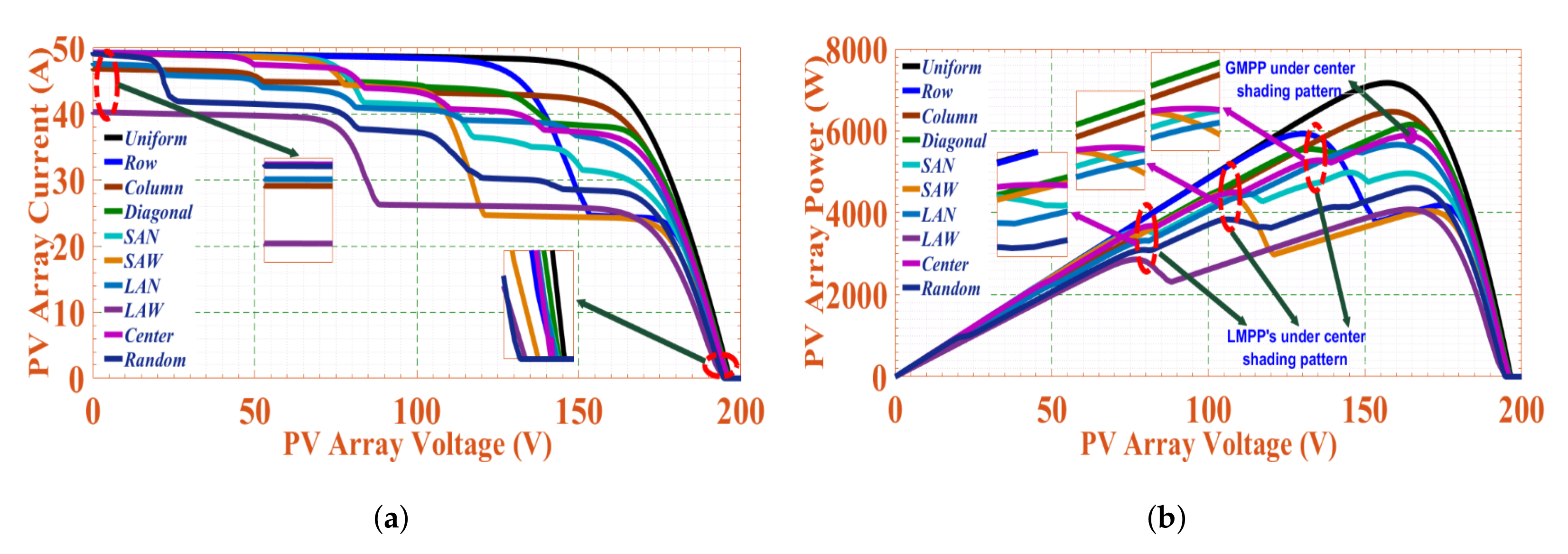
- Center: As shown in Figure 4i, the PV modules in array topologies placed at the center of fewer rows are shaded with different insolation levels. The PV modules numbered (23, 24), (33, 34), (43, 44) and (53, 54) receives an insolation of 300 W/m, 500 W/m, 700 W/m and 900 W/m, respectively. The rest of all the PV modules receives insolation of 1000 W/m.
5. Results and Disucussion
5.1. Under Uniform Shading Pattern
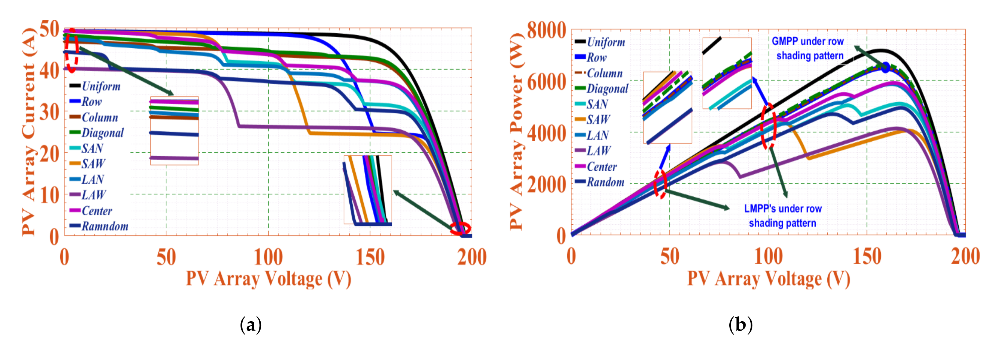
5.2. Under Uneven-Row Shading Pattern
5.3. Under Uneven-Column Shading Pattern
5.4. Under Diagonal Shading Pattern
5.5. Under SAN Shading Pattern
5.6. Under SAW Shading Pattern
5.7. Under LAN Shading Pattern
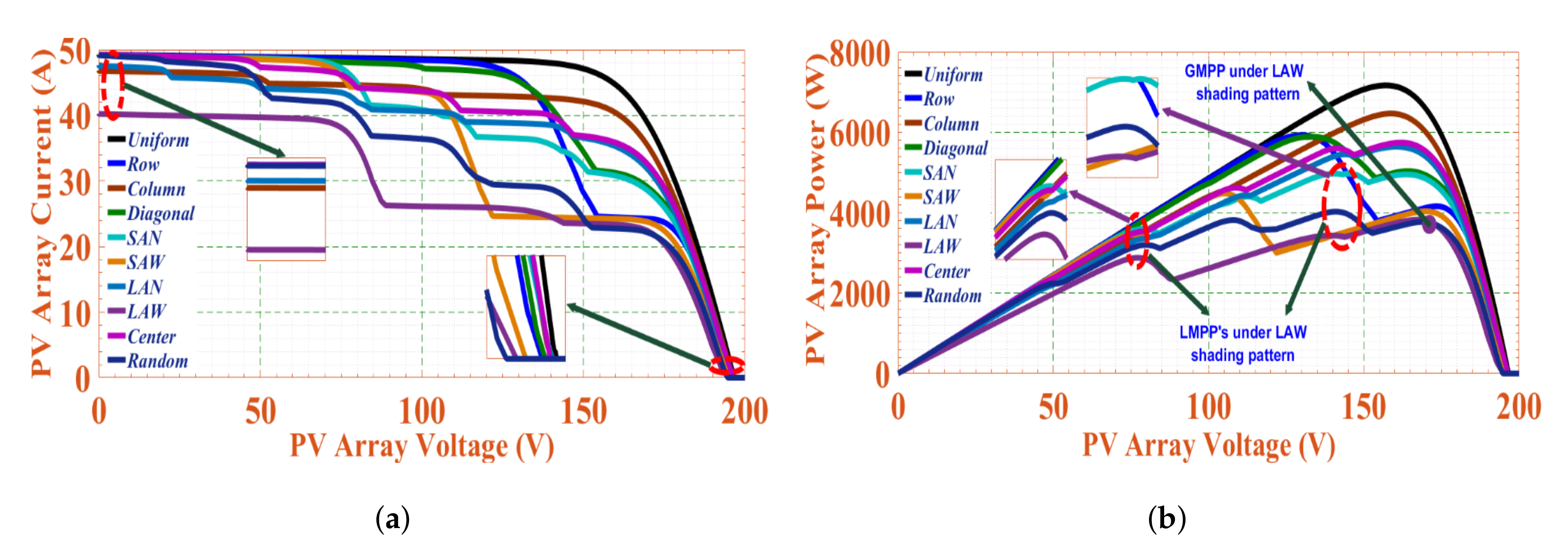
5.8. Under LAW Shading Pattern
5.9. Under Random Shading Pattern
5.10. Under Center Shading Pattern
6. Conclusions
Author Contributions
Funding
Conflicts of Interest
Nomenclature and Abbreviations
Nomenclature
| PV | Photovoltaic |
| S-S | Simple-Series |
| P | Parallel |
| S-P | Series-Parallel |
| T-C-T | Total-Cross-Tied |
| B-L | Bridge-Linked |
| H-C | Honey-Comb |
| S-P-C-T | Series-Parallel-Cross-Tied |
| B-L-C-T | Bridge-Linked-Cross-Tied |
| H-C-C-T | Honey-Comb-Cross-Tied |
| S-P-T-C-T | Series-Parallel-Total-Cross-Tied |
| B-L-T-C-T | Bridge-Linked-Total-Cross-Tied |
| H-C-T-C-T | Honey-Comb-Total-Cross-Tied |
| B-L-H-C | Bridge-Link-Honey-Comb |
| NUOC | Non-unioform Operating Condition |
| PID | Potential-Induced-Degradation |
| LMPP | Local-Maximum-Power-Point |
| GMPP | Global-Maximum-Power-Point |
| FF | Fill Factor |
Abbreviations
| [A] | PV module output current |
| [A] | Photo-generated current |
| [A] | Photo-generated current at STC |
| [A] | PV module short-circuit current at STC |
| & [A] | Diode reverse saturation currents |
| [A] | PV array output current |
| [V] | PV module output voltage |
| & [V] | Thermal voltages of the diodes |
| [V] | PV module open-circuit voltage at STC |
| [V] | PV array output voltage |
| PV module series resistance | |
| PV module shunt resistance | |
| & [V] | Diffusion and recombination current components of the diodes |
| G [A] | Solar insolation at the particular level |
| [V] | Solar insolation at the STC |
| Temperature co-efficient of short-circuit current | |
| Temperature co-efficient of open-circuit voltage¶ |
References
- Villalva, M.G.; Gazoli, J.R.; Filho, E.R. Comprehensive approach to modeling and simulation of photovoltaic arrays. IEEE Trans. Power Electron. 2019, 24, 1198–1208. [Google Scholar] [CrossRef]
- Ding, K.; Bian, X.G.; Liu, H.H.; Peng, T. A MATLAB-Simulink-based PV module model and its application under conditions of nonuniform irradiance. IEEE Trans. Energy Convers. 2012, 27, 864–872. [Google Scholar] [CrossRef]
- Veerasamy, B.; Takeshita, T.; Jote, A.; Mekonnen, T. Mismatch loss analysis of PV array configurations under partial shading conditions. In Proceedings of the 7th IEEE International Conference on Renewable Energy Research and Applications (ICRERA), Paris, France, 14–17 October 2018; pp. 1162–1167. [Google Scholar]
- Krishna, G.S.; Moger, T. Comparative Study on Solar Photovoltaic Array Configurations Under Irregular Irradiance Conditions. In Proceedings of the 8th IEEE Intenational Conference on Power Electronics (IICPE), Jaipur, India, 13–15 December 2018; pp. 1–6. [Google Scholar]
- Moballegh, S.; Jiang, J. Modeling, prediction, and experimental validations of power peaks of PV arrays under partial shading conditions. IEEE Trans. Sustain. Energy 2014, 5, 293–300. [Google Scholar] [CrossRef]
- Ahmed, J.; Salam, Z. An accurate method for MPPT to detect the partial shading occurrence in a PV system. IEEE Trans. Ind. Inform. 2017, 13, 2151–2161. [Google Scholar] [CrossRef]
- Manganiello, P.; Balato, M.; Vitelli, M. A survey on mismatching and aging of PV modules: The closed loop. IEEE Trans. Ind. Electron. 2015, 62, 7276–7286. [Google Scholar] [CrossRef]
- Gao, L.; Dougal, R.A.; Liu, S.; Iotova, A.P. Parallel-connected solar PV system to address partial and rapidly fluctuating shadow conditions. IEEE Trans. Ind. Electron. 2009, 56, 1548–1556. [Google Scholar]
- Petrone, G.; Spagnuolo, G.; Teodorescu, R.; Veerachary, M.; Vitell, M. Reliability issues in photovoltaic power processing systems. IEEE Trans. Ind. Electron. 2008, 55, 2569–2580. [Google Scholar] [CrossRef]
- Patel, H.; Agarwal, V. MATLAB-based modeling to study the effects of partial shading on PV array characteristics. IEEE Trans. Energy Convers. 2008, 23, 302–310. [Google Scholar] [CrossRef]
- Wu, D.; Sun, Y.; Zheng, F. Research of a new photovoltaic module. Int. J. Energy Res. 2019, 43, 7702–7709. [Google Scholar] [CrossRef]
- Jazayeri, M.; Uysal, S.; Jazayeri, K. A comparative study on different photovoltaic array topologies under partial shading conditions. In Proceedings of the 2014 IEEE PES T&D Conference and Exposition, Chicago, IL, USA, 14–17 April 2014; pp. 1–5. [Google Scholar]
- Ramaprabha, R.; Mathur, B.L. A comprehensive review and analysis of solar photovoltaic array configurations under partial shaded conditions. Int. J. Photoenergy 2012, 2012, 1–16. [Google Scholar] [CrossRef] [Green Version]
- Killi, M.; Samanta, S. Modified perturb and observe MPPT algorithm for drift avoidance in photovoltaic systems. IEEE Trans. Ind. Electron. 2015, 62, 5549–5559. [Google Scholar] [CrossRef]
- Subudhi, B.; Pradhan, R. A comparative study on maximum power point tracking techniques for photovoltaic power systems. IEEE Trans. Sustain. Energy 2012, 4, 89–98. [Google Scholar] [CrossRef]
- Garud, K.S.; Jayaraj, S.; Lee, M.-Y. A review on modeling of solar photovoltaic systems using artificial neural networks, fuzzy logic, genetic algorithm and hybrid models. Int. J. Energy Res. 2021, 45, 6–35. [Google Scholar] [CrossRef]
- Salam, Z.; Ahmed, J.; Merugu, B.S. The application of soft computing methods for MPPT of PV system: A technological and status review. Appl. Energy 2013, 107, 135–148. [Google Scholar] [CrossRef]
- Bastidas-Rodriguez, J.D.; Franco, E.; Petrone, G.; Ramos-Paja, C.A.; Spagnuolo, G. Maximum power point tracking architectures for photovoltaic systems in mismatching conditions: A review. IET Power Electron. 2014, 7, 1396–1413. [Google Scholar] [CrossRef]
- Agamy, M.S.; Harfman-Todorovic, M.; Elasser, A.; Chi, S.; Steigerwald, R.L.; Sabate, J.A.; McCann, A.J.; Zhang, L.; Mueller, F.J. An Efficient Partial Power Processing DC/DC Converter for Distributed PV Architectures. IEEE Trans. Power Electron. 2014, 29, 674–686. [Google Scholar] [CrossRef]
- Pilawa-Podgurski, R.C.N.; Perreault, D.J. Sub-module integrated distributed maximum power point tracking for solar photovoltaic applications. IEEE Trans. Power Electron. 2013, 28, 2957–2967. [Google Scholar] [CrossRef] [Green Version]
- Pendem, S.R.; Mikkili, S.; Bonthagorla, P.K. PV distributed-MPP tracking: Total-cross-tied configuration of string-integrated-converters to extract the maximum power under various PSCs. IEEE Syst. J. 2019, 14, 1046–1057. [Google Scholar] [CrossRef]
- Kouro, S.; Leon, J.I.; Vinnikov, J.I.; Franquelo, L.G. Grid-connected photovoltaic systems: An overview of recent research and emerging PV converter technology. IEEE Ind. Electron. Mag. 2015, 9, 47–61. [Google Scholar] [CrossRef]
- Jalilzadeh, T.; Rostami, N.; Babaei, E.; Maalandish, M. Non-isolated topology for high step-up dc-dc converters. IEEE J. Emerg. Sel. Topics Power Electron. 2018, 1. [Google Scholar] [CrossRef]
- Li, W.; He, X. Review of nonisolated high-step-up dc/dc converters in photovoltaic grid-connected applications. IEEE Trans. Ind. Electron. 2011, 58, 1239–1250. [Google Scholar] [CrossRef]
- Al-Soeidat, M.; Aljarajreh, H.; Khawaldeh, H.; Lu, D.D.; Zhu, J.G. A reconfigurable three-port dc-dc converter for integrated PV-battery system. IEEE J. Emerg. Sel. Topics Power Electron. 2019, 8, 3423–3433. [Google Scholar] [CrossRef]
- Freitas, A.A.; Tofoli, F.L.L.; Mineiro, S.; Daher, S.; Antunes, F.M. High-voltage gain dc-dc boost converter with coupled inductors for photovoltaic systems. IET Power Electron. 2015, 8, 1885–1892. [Google Scholar] [CrossRef] [Green Version]
- Romero-Cadaval, E.; Spagnuolo, G.; Franquelo, L.G.; Ramos-Paja, C.-A.; Suntio, T.; Xiao, W.-M. Grid-connected photovoltaic generation plants: Components and operation. IEEE Ind. Electron. Mag. 2013, 7, 6–20. [Google Scholar] [CrossRef] [Green Version]
- Li, Q.; Wolfs, P. A review of the single phase photovoltaic module integrated converter topologies with three different dc link configurations. IEEE Trans. Power Electron. 2008, 23, 1320–1333. [Google Scholar]
- Gupta, K.K.; Ranjan, A.; Bhatnagar, P.; Sahu, L.K.; Jain, S. Multilevel inverter topologies with reduced device count: A review. IEEE Trans. Power Electron. 2016, 31, 135–151. [Google Scholar] [CrossRef]
- Hassaine, L.; OLias, E.; Quintero, J.; Salas, V. Overview of power inverter topologies and control structures for grid connected photovoltaic systems. Renew. Sustain. Energy Rev. 2014, 30, 796–807. [Google Scholar] [CrossRef]
- Moses, A.; Sun, H. Bidirectional energy storage photovoltaic grid-connected inverter application system. Int. J. Energy Res. 2020, 44, 11509–11523. [Google Scholar] [CrossRef]
- Alhafadhi, L.; Teh, J. Advances in reduction of total harmonic distortion in solar photovoltaic systems: A literature review. Int. J. Energy Res. 2020, 44, 2455–2470. [Google Scholar] [CrossRef]
- Khan, M.N.H.; Forouzesh, M.; Siwakoti, Y.P.; Li, L.; Kerekes, T.; Blaabjerg, F. Transformerless inverter topologies for single-phase photovoltaic systems: A comparative review. IEEE J. Emerg. Sel. Topics Power Electron. 2020, 8, 805–835. [Google Scholar] [CrossRef]
- Pendem, S.R.; Mikkili, S. Modelling and performance assessment of PV array topologies under partial shading conditions to mitigate the mismatching power losses. Sol. Energy 2018, 160, 303–321. [Google Scholar] [CrossRef]
- Gautam, N.K.; Kaushika, N. Reliability evaluation of solar photovoltaic arrays. Sol. Energy 2002, 72, 129–141. [Google Scholar] [CrossRef]
- Bosco, M.J.; Mabel, M.C. A novel cross diagonal view configuration of a PV system under partial shading condition. Sol. Energy 2017, 158, 760–773. [Google Scholar] [CrossRef]
- Bonthagorla, P.K.; Mikkili, S. A novel fixed PV array configuration for harvesting maximum power from shaded modules by reducing the number of cross-ties. IEEE J. Emerg. Sel. Topics Power Electron. 2020, 9, 2109–2121. [Google Scholar] [CrossRef]
- Lappalainen, K.; Valkealahti, S. Effects of irradiance transition characteristics on the mismatch losses of different electrical PV array configurations. IET Renew. Power Gener. 2016, 11, 248–254. [Google Scholar] [CrossRef]
- Rao, P.S.; Ilango, G.S.; Nagamani, C. Maximum power from PV arrays using a fixed configuration under different shading conditions. IEEE J. Photovoltaics 2014, 4, 679–686. [Google Scholar]
- Horoufiany, M.; Ghandehari, R. Optimal fixed reconfiguration scheme for PV arrays power enhancement under mutual shading conditions. IET Renew. Power Gener. 2017, 11, 1456–1463. [Google Scholar] [CrossRef]
- Sahu, H.S.; Nayak, S.K. Extraction of maximum power from a PV array under nonuniform irradiation conditions. IEEE Trans. Electron Devices 2016, 63, 4825–4831. [Google Scholar] [CrossRef]
- Rani, B.I.; Ilango, G.S.; Nagamani, C. Enhanced power generation from PV array under partial shading conditions by shade dispersion using Su Do Ku configuration. IEEE Trans. Sustain. Energy 2013, 4, 594–601. [Google Scholar] [CrossRef]
- Krishna, S.G.; Moger, T. Optimal SuDoKu reconfiguration technique for total-cross-tied PV array to increase power output under non-uniform irradiance. IEEE Trans. Energy Convers. 2019, 34, 1973–1984. [Google Scholar] [CrossRef]
- Yadav, A.S.; Pachauri, R.K.; Chauhan, Y.K. Comprehensive Investigation of PV arrays with puzzle shade dispersion for improved performance. Sol. Energy. 2016, 129, 256–285. [Google Scholar] [CrossRef]
- Vijayalekshmy, S.; Bindu, G.R.; Iyer, S.R. A novel zig-zag scheme for power enhancement of partially shaded solar arrays. Sol. Energy 2016, 135, 92–102. [Google Scholar] [CrossRef]
- Dhanalakshmi, B.; Rajasekar, N. Dominance square based array reconfiguration scheme for power loss reduction in solar PhotoVoltaic (PV) systems. Energy Convers. Manag. 2015, 156, 84–102. [Google Scholar] [CrossRef]
- Rakesh, N.; Kumar, S.S.; Madhusudanan, G. Mitigation of power mismatch losses and wiring line losses of partially shaded solar PV array using improvised magic technique. IET Renew. Power Gener. 2019, 13, 1522–1532. [Google Scholar] [CrossRef]
- Nguyen, D.; Lehman, B. An adaptive solar photovoltaic array using model-based reconfiguration algorithm. IEEE Trans. Ind. Electron. 2008, 55, 2644–2654. [Google Scholar] [CrossRef]
- Velasco-Quesada, G.; Guinjoan-Gispert, F.; Pique-Lopez, R.; Roman-Lumbreras, M.; Conesa-Roca, A. Electrical PV array reconfiguration strategy for energy extraction improvement in grid-connected PV systems. IEEE Trans. Ind. Electron. 2009, 56, 4319–4331. [Google Scholar] [CrossRef] [Green Version]
- Deshkar, S.N.; Dhale, S.B.; Mukherjee, J.S.; Babu, T.S.; Rajasekar, N. Solar PV array reconfiguration under partial shading conditions for maximum power extraction using genetic algorithm. Renew. Sustain. Energy Rev. 2015, 43, 102–110. [Google Scholar] [CrossRef]
- Babu, T.S.; Prasanth Ram, J.; Dragicevic, T.; Miyatake, M.; Blaabjerg, F.; Rajasekar, N. Particle swarm optimization based solar PV array reconfiguration of the maximum power extraction under partial shading conditions. IEEE Trans. Sustain. Energy 2018, 9, 74–85. [Google Scholar] [CrossRef]
- Manjunath, M.; Reddy, B.V.; Lehman, B. Performance improvement of dynamic PV array under partial shade conditions using M2 algorithm. IET Renew. Power Gener. 2019, 13, 1239–1249. [Google Scholar] [CrossRef]
- Balato, M.; Manganiello, P.; Vitelli, M. Fast dynamical reconfiguration algorithm of PV arrays. In Proceedings of the 9th IEEE International Conference on Ecological Vehicles and Renewable Energies (EVER), Monte-Carlo, Monaco, 25–27 March 2014; pp. 1–8. [Google Scholar]
- Balato, M.; Costanzo, L.; Vitelli, M. Multi-objective optimization of PV arrays performances by means of the dynamical reconfiguration of PV modules connections. In Proceedings of the 2015 IEEE International Conference on Renewable Energy Research and Applications (ICRERA), Palermo, Italy, 22–25 November 2015; pp. 1646–1650. [Google Scholar]
- Storey, J.P.; Wilson, P.R.; Bagnall, D. Improved Optimization Strategy for Irradiance Equalization in Dynamic Photovoltaic Arrays. IEEE Trans. Power Electron. 2013, 28, 2946–2956. [Google Scholar] [CrossRef]
- Aldaoudeyeh, A.M.I. Photovoltaic-battery scheme to enhance PV array characteristics in partial shading conditions. IET Renew. Power Gener. 2016, 10, 108–115. [Google Scholar] [CrossRef]
- Sharma, P.; Agarwal, V. Maximum power extraction from a partially shaded PV array using shunt-series compensation. IEEE J. Photovoltaics 2014, 4, 1128–1137. [Google Scholar] [CrossRef]
- Pendem, S.R.; Mikkili, S. Modeling, simulation, and performance analysis of PV array configurations (series, series-parallel, bridge-linked, and honey-comb) to harvest maximum power under various partial shading conditions. Int. J. Green Energy 2018, 15, 795–812. [Google Scholar] [CrossRef]
- Shongwe, S.; Hanif, M. Comparative analysis of different single-diode PV modeling methods. IEEE J. Photovoltaics 2015, 5, 938–946. [Google Scholar] [CrossRef]
- Ma, J.; Man, K.; Guan, S.-U.; Ting, T.; Wong, P. Parameter estimation of photovoltaic model via parallel particle swarm optimization algorithm. Int. J. Energy Res. 2015, 40, 343–352. [Google Scholar] [CrossRef]
- Ishaque, K.; Salam, Z.; Taheri, H. Accurate MATLAB Simulink pv system simulator based on a two-diode model. Jour. Power Electron. 2011, 11, 17–187. [Google Scholar] [CrossRef] [Green Version]
- Villalva, M.G.; Gazoli, J.R.; Filho, E.R. Modeling and circuit-based simulation of photovoltaic arrays. In Proceedings of the 2009 Brazilian Power Electronics Conference (COBEP), Bonito-Mato Grosso do Sul, Brazil, 27 September–1 October 2009; pp. 1244–1254. [Google Scholar]
- Agrawal, N.; Bora, B.; Kapoor, A. Experimental investigations of fault tolerance due to shading in photovoltaic modules with different interconnected solar cell networks. Sol. Energy 2020, 211, 1239–1254. [Google Scholar] [CrossRef]
- Rao, P.S.; Dinesh, P.; Ilango, G.S.; Nagamani, C. Optimal Su-Do-Ku based interconnection scheme for increased power output from PV array under partial shading conditions. Front. Energy 2015, 9, 199–210. [Google Scholar]


| S.No. | Topology | Array Voltage | Array Current |
|---|---|---|---|
| 1 | S-S | ||
| 2 | S-P | ||
| 3 | T-C-T | ||
| 4 | B-L | ||
| 5 | H-C | ||
| 6 | S-P-C-T | ||
| 7 | B-L-C-T | ||
| 8 | H-C-C-T | ||
| 9 | S-P-T-C-T | ||
| 10 | B-L-T-C-T | ||
| 11 | H-C-T-C-T | ||
| 12 | B-L-H-C |
| Configuration | Voc (V) | Isc (A) | GMPP Parameters | LMPP’s | No. of Peaks | Fill Factor | ||
|---|---|---|---|---|---|---|---|---|
| Vmp (V) | Imp (A) | Pmp (W) | ||||||
| S-P | 196.60 | 49.26 | 129.98 | 45.63 | 5930.80 | 4117.00 W | 01 | 0.61 |
| B-L | 196.10 | 49.26 | 129.98 | 45.63 | 5930.80 | 4190.95 W | 01 | 0.61 |
| H-C | 196.10 | 49.26 | 129.98 | 45.63 | 5930.80 | 4183.20 W | 01 | 0.61 |
| S-P-C-T | 196.10 | 49.26 | 129.98 | 45.63 | 5930.80 | 4190.95 W | 01 | 0.61 |
| B-L-C-T | 196.10 | 49.26 | 129.98 | 45.63 | 5930.80 | 4198.35 W | 01 | 0.61 |
| H-C-C-T | 196.10 | 49.26 | 129.98 | 45.63 | 5930.80 | 4190.95 W | 01 | 0.61 |
| S-P-T-C-T | 196.10 | 49.26 | 129.98 | 45.63 | 5930.80 | 4190.95 W | 01 | 0.61 |
| B-L-T-C-T | 196.10 | 49.26 | 129.98 | 45.63 | 5930.80 | 4198.35 W | 01 | 0.61 |
| H-C-T-C-T | 196.30 | 49.26 | 157.04 | 41.01 | 6492.75 | 1971.88 W; 4438.85 W | 02 | 0.67 |
| B-L-H-C | 196.10 | 49.26 | 129.98 | 45.63 | 5930.80 | 4162.04 W | 01 | 0.61 |
| Configuration | Voc (V) | Isc (A) | GMPP Parameters | LMPP’s | No. of Peaks | Fill Factor | ||
|---|---|---|---|---|---|---|---|---|
| Vmp (V) | Imp (A) | Pmp (W) | ||||||
| S-P | 196.60 | 46.89 | 157.56 | 40.34 | 6355.80 | 2363.15 W; 5041.65 W | 02 | 0.65 |
| B-L | 196.30 | 46.89 | 158.49 | 40.63 | 6439.10 | 2333.20 W; 2575.10 W | 02 | 0.66 |
| H-C | 196.20 | 46.89 | 158.68 | 40.75 | 6465.80 | 2338.25 W; 4568.73 W | 02 | 0.67 |
| S-P-C-T | 196.30 | 46.89 | 158.17 | 40.85 | 6460.90 | 2314.45 W; 4409.00 W | 02 | 0.66 |
| B-L-C-T | 196.30 | 46.89 | 158.78 | 40.84 | 6483.95 | 2128.63 W; 4402.54 W | 02 | 0.67 |
| H-C-C-T | 196.30 | 46.88 | 158.22 | 41.01 | 6489.20 | 2695.50 W | 01 | 0.67 |
| S-P-T-C-T | 196.30 | 46.89 | 158.36 | 41.00 | 6493.85 | 4499.29 W | 01 | 0.67 |
| B-L-T-C-T | 196.30 | 46.89 | 158.23 | 41.03 | 6492.85 | 1982.89 W; 4473.09 W | 02 | 0.67 |
| H-C-T-C-T | 196.30 | 46.88 | 158.32 | 41.01 | 6492.75 | 1971.88 W; 4438.85 W | 02 | 0.67 |
| B-L-H-C | 196.50 | 46.89 | 158.68 | 40.75 | 6465.70 | 2510.30 W; 4547.00 W | 02 | 0.66 |
| Configuration | Voc (V) | Isc (A) | GMPP Parameters | LMPP’s | No. of Peaks | Fill Factor | ||
|---|---|---|---|---|---|---|---|---|
| Vmp (V) | Imp (A) | Pmp (W) | ||||||
| S-P | 196.40 | 49.26 | 129.98 | 45.63 | 5980.30 | 4748.12 W | 01 | 0.61 |
| B-L | 196.50 | 48.52 | 159.50 | 41.24 | 6578.50 | 947.96 W; 2625.30 W 3434.10 W; 4471.80 W | 04 | 0.68 |
| H-C | 196.40 | 49.26 | 164.54 | 37.39 | 6152.82 | 3567.84 W; 4510.41 W; 5560.90 W | 03 | 0.63 |
| S-P-C-T | 196.50 | 49.26 | 135.85 | 41.94 | 5697.25 | 4918.00 W; 5412.00 W | 02 | 0.59 |
| B-L-C-T | 196.40 | 49.20 | 159.20 | 41.07 | 6538.30 | 2534.40 W | 01 | 0.67 |
| H-C-C-T | 196.40 | 49.26 | 158.99 | 41.21 | 6551.40 | 2279.00 W | 01 | 0.68 |
| S-P-T-C-T | 196.50 | 49.26 | 133.12 | 44.35 | 5904.15 | 5418.05 W | 01 | 0.61 |
| B-L-T-C-T | 196.40 | 48.45 | 159.43 | 41.35 | 6593.25 | 3255.46 W; 4461.34 W; 5633.76 W | 03 | 0.68 |
| H-C-T-C-T | 196.40 | 48.51 | 159.19 | 41.49 | 6605.05 | 3305.15 W; 4420.89 W; 5549.84 W | 03 | 0.68 |
| B-L-H-C | 196.20 | 49.26 | 133.63 | 44.06 | 5887.45 | 4951.88 W; 5035.17 W | 02 | 0.60 |
| Configuration | Voc (V) | Isc (A) | GMPP Parameters | LMPP’s | No. of Peaks | Fill Factor | ||
|---|---|---|---|---|---|---|---|---|
| Vmp (V) | Imp (A) | Pmp (W) | ||||||
| S-P | 196.60 | 49.25 | 145.56 | 35.53 | 5173.00 | 3624.96 W; 4545.82 W; 4751.67 W | 03 | 0.53 |
| B-L | 196.40 | 49.26 | 165.03 | 30.57 | 5046.60 | 3517.50 W; 4429.20 W; 4947.60 W | 03 | 0.52 |
| H-C | 196.30 | 49.26 | 145.12 | 34.37 | 4988.30 | 1640.17 W; 3580.17 W; 4494.66 W; 4965.07W | 04 | 0.51 |
| S-P-C-T | 196.60 | 49.26 | 165.59 | 30.57 | 5063.25 | 3456.35 W; 4389.85 W; 5060.10 W | 03 | 0.52 |
| B-L-C-T | 196.50 | 49.25 | 166.86 | 30.75 | 5132.75 | 3455.55 W; 4386.75 W; 4923.70 W | 03 | 0.53 |
| H-C-C-T | 196.60 | 49.26 | 166.36 | 30.65 | 5099.50 | 3456.20 W; 4354.70 W; 5036.00 W | 03 | 0.53 |
| S-P-T-C-T | 196.60 | 49.26 | 165.59 | 30.57 | 5063.25 | 3456.25 W; 4389.85 W; 5060.05 W | 03 | 0.52 |
| B-L-T-C-T | 196.50 | 49.26 | 166.87 | 30.75 | 5132.65 | 3456.15 W; 4387.05 W; 4923.65 W | 03 | 0.53 |
| H-C-T-C-T | 196.60 | 49.26 | 166.42 | 30.64 | 5099.45W | 3456.15 W; 4354.65 W; 5035.95 W | 03 | 0.52 |
| B-L-H-C | 196.50 | 49.26 | 140.59 | 35.37 | 4973.50 | 1316.50 W; 3598.60 W; 4401.40 W; 4952.20 W; | 03 | 0.51 |
| Configuration | Voc (V) | Isc (A) | GMPP Parameters | LMPP’s | No. of Peaks | Fill Factor | ||
|---|---|---|---|---|---|---|---|---|
| Vmp (V) | Imp (A) | Pmp (W) | ||||||
| S-P | 195.10 | 49.25 | 166.34 | 23.51 | 3911.46 | 3455.96 W | 01 | 0.40 |
| B-L | 195.50 | 49.26 | 105.33 | 42.53 | 4480.20 | 3456.10 W; 4040.20 W | 02 | 0.46 |
| H-C | 195.50 | 49.26 | 105.15 | 42.60 | 4480.16 | 3456.10 W; 4046.28 W | 02 | 0.46 |
| S-P-C-T | 195.50 | 49.26 | 105.24 | 42.56 | 4480.25 | 3456.25 W; 4055.55 W | 02 | 0.46 |
| B-L-C-T | 195.50 | 49.25 | 105.24 | 42.57 | 4480.25 | 3456.25 W; 4058.65 W | 02 | 0.46 |
| H-C-C-T | 195.50 | 49.25 | 105.15 | 42.60 | 4480.20 | 3456.20 W; 4056.60 W | 02 | 0.46 |
| S-P-T-C-T | 195.50 | 49.26 | 105.24 | 42.56 | 4480.25 | 3456.25 W; 4060.15 W | 02 | 0.46 |
| B-L-T-C-T | 195.50 | 49.26 | 105.19 | 42.58 | 4480.15 | 3456.15 W; 4058.55 W | 02 | 0.46 |
| H-C-T-C-T | 195.50 | 49.26 | 105.20 | 42.58 | 4480.15 | 3456.15 W; 4056.55 W | 02 | 0.46 |
| B-L-H-C | 195.50 | 49.26 | 105.15 | 42.60 | 4480.20 | 3456.20 W; 4034.80 W | 02 | 0.46 |
| Configuration | Voc (V) | Isc (A) | GMPP Parameters | LMPP’s | No. of Peaks | Fill Factor | ||
|---|---|---|---|---|---|---|---|---|
| Vmp (V) | Imp (A) | Pmp (W) | ||||||
| S-P | 196.60 | 47.71 | 158.28 | 35.06 | 5549.50 | 1060.69 W; 2280.64 W; 3513.34 W; 4598.32 W | 04 | 0.57 |
| B-L | 196.20 | 47.54 | 160.92 | 35.54 | 5719.90 | 1027.00 W; 2161.00 W; 3414.10 W; 4522.20 W; 5160.00 W | 05 | 0.59 |
| H-C | 196.30 | 47.70 | 145.95 | 37.66 | 5496.25 | 2279.00 W; 3322.72 W; 4433.00 W | 03 | 0.57 |
| S-P-C-T | 196.30 | 47.72 | 161.60 | 35.89 | 5801.10 | 4314.55 W; 5308.75 W | 02 | 0.60 |
| B-L-C-T | 196.20 | 47.70 | 162.00 | 35.96 | 5826.00 | 983.65 W; 2149.05 W; 3113.07 W; 4322.00 W; 5226.00 W | 05 | 0.60 |
| H-C-C-T | 196.30 | 47.70 | 162.25 | 36.11 | 5860.10 | 3185.80 W; 4325.50 W; 5130.90 W | 03 | 0.60 |
| S-P-T-C-T | 196.30 | 47.71 | 161.61 | 35.93 | 5807.65 | 3211.35 W; 4337.85 W; 5319.85 W | 03 | 0.60 |
| B-L-T-C-T | 196.20 | 47.70 | 162.09 | 35.96 | 5830.55 | 844.15 W; 2018.25 W; 3211.25 W; 4337.45 W; 5234.05 W | 05 | 0.60 |
| H-C-T-C-T | 196.30 | 47.69 | 162.47 | 36.08 | 5863.35 | 854.86 W; 2031.24 W; 3161.04 W; 4318.02 W; 5118.99 W | 05 | 0.60 |
| B-L-H-C | 196.50 | 47.70 | 160.43 | 35.16 | 5641.2 | 3443.79 W; 4432.74 W; 5450.95 W | 03 | 0.58 |
| Configuration | Voc (V) | Isc (A) | GMPP Parameters | LMPP’s | No. of Peaks | Fill Factor | ||
|---|---|---|---|---|---|---|---|---|
| Vmp (V) | Imp (A) | Pmp (W) | ||||||
| S-P | 196.60 | 40.31 | 163.67 | 24.63 | 4032.50 | 2892.59 W | 01 | 0.57 |
| B-L | 194.90 | 40.30 | 164.07 | 25.03 | 4107.10 | 2454.10 W; 2843.10 W | 02 | 0.42 |
| H-C | 194.90 | 40.31 | 163.98 | 24.91 | 4085.50 | 2863.30 W | 01 | 0.42 |
| S-P-C-T | 195.80 | 40.30 | 165.34 | 25.04 | 4140.45 | 2841.95 W | 01 | 0.43 |
| B-L-C-T | 194.90 | 40.30 | 165.20 | 25.06 | 4140.65 | 2843.05 W | 01 | 0.43 |
| H-C-C-T | 195.10 | 40.30 | 165.01 | 25.09 | 4140.70 | 2843.10 W | 01 | 0.43 |
| S-P-T-C-T | 195.80 | 40.31 | 165.20 | 25.06 | 4140.65 | 2843.15 W | 01 | 0.43 |
| B-L-T-C-T | 194.90 | 40.31 | 165.07 | 25.08 | 4140.65 | 2843.05 W | 01 | 0.43 |
| H-C-T-C-T | 195.10 | 40.30 | 165.07 | 25.08 | 4140.65 | 2842.55 W | 01 | 0.43 |
| B-L-H-C | 195.10 | 40.31 | 167.29 | 22.86 | 3823.80 | 2876.80 W; 3433.10 W | 02 | 0.39 |
| Configuration | Voc (V) | Isc (A) | GMPP Parameters | LMPP’s | No. of Peaks | Fill Factor | ||
|---|---|---|---|---|---|---|---|---|
| Vmp (V) | Imp (A) | Pmp (W) | ||||||
| S-P | 194.80 | 49.25 | 110.06 | 36.26 | 3991.80 | 2255.29 W; 2814.79 W; 3410.22 W; 3910.54W | 04 | 0.41 |
| B-L | 194.60 | 48.52 | 134.24 | 33.90 | 4551.47 | 927.48 W; 2139.20 W; 2968.46 W; 3802.01W; 3869.46W | 05 | 0.47 |
| H-C | 194.70 | 49.26 | 165.69 | 27.81 | 4609.88 | 982.61 W; 3095.67 W; 3656.66 W; 3841.5W; 4145.06W | 05 | 0.47 |
| S-P-C-T | 195.40 | 46.95 | 168.39 | 23.86 | 4018.95 | 2310.15 W; 3132.65 W; 3827.75 W; 3841.45W | 04 | 0.41 |
| B-L-C-T | 194.70 | 46.04 | 166.88 | 27.74 | 4629.95 | 892.35 W; 2014.65 W; 3963.05 W; 4384.95W | 04 | 0.48 |
| H-C-C-T | 194.60 | 46.04 | 167.74 | 26.19 | 4394.60 | 3811.90 W; 4046.80 W; 4157.90 W | 03 | 0.45 |
| S-P-T-C-T | 195.30 | 46.95 | 133.11 | 34.84 | 4638.35 | 1021.95 W; 1981.45 W; 4553.65 W | 03 | 0.48 |
| B-L-T-C-T | 194.80 | 41.95 | 163.93 | 31.83 | 5218.25 | 825.53 W; 2796.64 W; 4692.15 W | 03 | 0.54 |
| H-C-T-C-T | 194.70 | 44.42 | 167.28 | 29.52 | 4938.55 | 817.76 W; 2825.46 W; 4696.85 W | 03 | 0.51 |
| B-L-H-C | 194.70 | 49.26 | 140.90 | 28.57 | 4026.60 | 2237.20 W; 3196.70 W; 3816.00 W; 3766.90 W | 04 | 0.41 |
| Configuration | Voc (V) | Isc (A) | GMPP Parameters | LMPP’s | No. of Peaks | Fill Factor | ||
|---|---|---|---|---|---|---|---|---|
| Vmp (V) | Imp (A) | Pmp (W) | ||||||
| S-P | 196.60 | 49.25 | 146.46 | 39.30 | 5757.66 | 2302.07 W; 3692.13 W; 4844.40 W; 5516.81 W | 04 | 0.59 |
| B-L | 196.10 | 49.25 | 162.28 | 36.01 | 5844.30 | 2294.88 W; 3533.20 W; 4695.60 W; 5369.00 W | 04 | 0.60 |
| H-C | 196.00 | 49.25 | 163.52 | 35.99 | 5884.70 | 3687.00 W; 4500.40 W; 5283.20 W | 03 | 0.60 |
| S-P-C-T | 196.40 | 49.26 | 161.93 | 35.92 | 5817.55 | 3687.25 W; 4453.95 W; 5515.15W | 03 | 0.60 |
| B-L-C-T | 196.10 | 49.26 | 162.73 | 36.05 | 5867.25 | 3630.15 W; 4490.65 W; 5454.35 W | 03 | 0.60 |
| H-C-C-T | 196.40 | 49.26 | 163.54 | 36.09 | 5902.60 | 4447.40 W; 5464.70 W | 02 | 0.61 |
| S-P-T-C-T | 196.40 | 49.26 | 162.10 | 35.95 | 5827.75 | 3506.55 W; 4557.75 W; 5551.55 W | 03 | 0.60 |
| B-L-T-C-T | 196.20 | 49.26 | 162.82 | 36.06 | 5872.75 | 2157.41 W; 3505.05 W; 4556.35 W | 03 | 0.60 |
| H-C-T-C-T | 196.40 | 49.26 | 163.76 | 36.06 | 5906.25 | 2082.73 W; 3386.77 W; 4459.07 W; 5462.82 W | 04 | 0.61 |
| B-L-H-C | 196.40 | 49.26 | 161.95 | 35.45 | 5741.70 | 3535.10 W; 4621.80 W; 5601.40 W | 03 | 0.59 |
Publisher’s Note: MDPI stays neutral with regard to jurisdictional claims in published maps and institutional affiliations. |
© 2021 by the authors. Licensee MDPI, Basel, Switzerland. This article is an open access article distributed under the terms and conditions of the Creative Commons Attribution (CC BY) license (https://creativecommons.org/licenses/by/4.0/).
Share and Cite
Raju Pendem, S.; Mikkili, S.; Rangarajan, S.S.; Avv, S.; Collins, R.E.; Senjyu, T. Optimal Hybrid PV Array Topologies to Maximize the Power Output by Reducing the Effect of Non-Uniform Operating Conditions. Electronics 2021, 10, 3014. https://doi.org/10.3390/electronics10233014
Raju Pendem S, Mikkili S, Rangarajan SS, Avv S, Collins RE, Senjyu T. Optimal Hybrid PV Array Topologies to Maximize the Power Output by Reducing the Effect of Non-Uniform Operating Conditions. Electronics. 2021; 10(23):3014. https://doi.org/10.3390/electronics10233014
Chicago/Turabian StyleRaju Pendem, Suneel, Suresh Mikkili, Shriram S. Rangarajan, Sudhakar Avv, Randolph E. Collins, and Tomonobu Senjyu. 2021. "Optimal Hybrid PV Array Topologies to Maximize the Power Output by Reducing the Effect of Non-Uniform Operating Conditions" Electronics 10, no. 23: 3014. https://doi.org/10.3390/electronics10233014
APA StyleRaju Pendem, S., Mikkili, S., Rangarajan, S. S., Avv, S., Collins, R. E., & Senjyu, T. (2021). Optimal Hybrid PV Array Topologies to Maximize the Power Output by Reducing the Effect of Non-Uniform Operating Conditions. Electronics, 10(23), 3014. https://doi.org/10.3390/electronics10233014