
Novel Step-Up Topologies of Zigzag Autotransformer

School of Electrical Engineering, Xi’an Jiaotong University, Xi’an 710049, China
*
Author to whom correspondence should be addressed.
Electronics 2021, 10(24), 3071; https://doi.org/10.3390/electronics10243071
Submission received: 19 October 2021
/
Revised: 22 November 2021
/
Accepted: 26 November 2021
/
Published: 9 December 2021
(This article belongs to the Section Power Electronics)
Abstract
:Zigzag autotransformer is widely used in multi-pulse rectifier system. However, the traditional zigzag autotransformer does not have the step-up function. Meanwhile, by improving the zigzag autotransformer structure, the output voltage can be increased without additional auxiliary components. Therefore, based on the 12 pulse rectifier system, this paper analyzes and designs three zigzag autotransformer step-up topologies, establishes the corresponding mathematical topology, studies the relationship between the transformation ratio and system main parameters, and deduces the step-up range of the three topologies. When the transformation ratio is greater than or equal to 1.0353 and less than 2.0705 and when the transformation ratio is greater than or equal to 2.0705, the equivalent capacity of the three topologies are compared. Based on the comparison, the optimal topology is obtained in different cases. Finally, according to the theoretical analysis, the simulation parameters are set, the simulation circuit is built, and the results are analyzed combined with corresponding mathematical topologies.
1. Introduction
In recent years, with the needs of social production, the control technology with power switch has developed vigorously. Diode and thyristor have become the core control devices because of their low cost, good performance and high reliability. However, high frequency switches also cause harmonic pollution to the power grid system. Multi-pulse rectifier harmonic suppression circuit has high power density, simple control circuit and easy maintenance which has been widely used in industrial and agricultural production [1,2,3,4].
Multi-pulse rectifier can rectify the output voltage at the grid side with a small amount of ripple through rectifier bridge and phase-shifting transformer. In theory, with the increase of the number of rectifier bridges, the ripple content of DC side voltage and the current harmonic content of grid will be less and less [5]. Scholars have successively studied 12, 18, 24 and 36 pulse phase-shifting rectification technology [6,7,8,9]. The theory of 12 pulse rectification has developed for a long time and plays an irreplaceable role in the field of multi-pulse basic research [10,11,12].
The phase-shifting transformer can convert the output voltage at the grid side into multiple groups of equal amplitude voltages with a certain phase angle. The mainstream phase-shifting transformer has two connection modes: isolated and self-coupling [13]. With different winding impedance on both sides and uneven magnetic flux leakage inductance, isolated connection, e.g., Δ/Y/Δ connection mode, are easy to cause output voltage imbalance. At the same time, due to the isolated connection between the primary winding and the secondary winding of the autotransformer, the energy transmission efficiency is low, resulting in large volume of transformer. The electromagnetic coupling degree of the autotransformer windings is stronger than that of the isolation transformer, and the magnetic circuit only undertakes a small part of energy transmission. Compared with the isolated transformer, it greatly improves the power density, reduces the volume of the transformer and saves the cost of the transformer [14,15,16]. The iron core of autotransformer has multiple windings, and multiple windings share one iron core, which can reduce the volume of the transformer itself. Therefore, it is more suitable for occasions with small gap. Meanwhile, the autotransformer winding mode and turns of the three core coils are symmetrical, which can eliminate the imbalance of the output voltage. Compared with the isolated transformer, the autotransformer can provide a more stable operating environment for the electric equipment on the DC side [17,18]. The phase shift angle of the transformer is an important factor affecting the current harmonic content at the AC side. Previous research results show that when the phase shift angle is designed as 15° in the design of autotransformer, the current harmonic content of AC side of multi pulse rectifier system is smaller than that when the phase shift angle takes other values. From the perspective of restraining AC side current harmonic, taking 15° phase shift angle of autotransformer is the best choice. Therefore, in order to optimize the harmonic suppression effect of the autotransformer designed in this paper, the phase shift angle of the autotransformer is also 15° [19].
Theoretically, the phase-shifting transformer can completely eliminate the corresponding characteristic harmonic by outputting multi-pulse current. According to the practical needs, domestic and foreign scholars have studied and expanded a variety of phase-shifting transformer topologies, which has laid a theoretical and practical foundation for the further development of multi-pulse rectifier technology [18,19]. However, the optimization and reconstruction of the autotransformer are mostly to generate more pulses at the output side of the autotransformer and reduce the harmonic content at the grid side, while there are few studies on the step-up of the autotransformer [20,21].
Zigzag autotransformer and its reconstruction structure are one of many research results. Its special structure presents high impedance to zero sequence current, so that the DC side circuit does not need zero sequence impedance suppressor, thus reducing the complexity and cost of DC side circuit [22].
Consequently, based on the zigzag topology, this paper establishes the mathematical topology between the transformation ratio and the main parameters of the system, gives the circuit equations under different mathematical topologies, and solves the equivalent capacity of the grid side harmonic wave and the main magnetic devices of the system under different topologies. According to the conclusion of theoretical analysis, the influence of transformation ratio on the main parameters of each topology is further discussed and compared with the simulation results. Finally, the zigzag autotransformer simulation circuit based on 12 pulse rectifier system is built on the MATLAB/Simulink, and the optimal step-up topology suitable for step-up occasions is obtained.
2. Three Step-Up Topologies of Zigzag Autotransformer
2.1. 12-Pulse Rectifier System
Firstly, the 12-pulse rectifier system is introduced. The zigzag autotransformer is used as the phase-shifting transformer. The system diagram is shown in Figure 1.
In Figure 1, the left source voltage is phase shifted through the zigzag phase-shifting transformer to generate two groups of three-phase balanced voltages with equal amplitude and a certain angle difference, which are used to supply the rectifier bridge. The DC side is mainly composed of balance reactor and load. The output voltage of the rectifier bridge supplies the voltage with a small amount of ripple to the load through the balance reactor.
In Figure 1, the power supply voltage frequency f is 50 Hz. Generally, the input three-phase voltage of three-phase circuit is expressed as:
where ω = 2πf, Um is the maximum power supply voltage at the network side.
Assuming that the DC side current is a standard flat wave, that is, the relative resistance of the load inductance is large enough, then:
where Id corresponds to the main current on the right side of Figure 1 and is its root mean square value.
2.2. Step-Up Topology Design of Zigzag Autotransformer
In Figure 2, in order to minimize the harmonic at the grid side, the autotransformer generally selects 30° as its phase shift angle [19].
Assuming:
where KT represents the voltage at the output side under the unit input voltage, and the greater KT represents the greater the voltage at the output side under the unit input voltage.
In view of the symmetry of autotransformer, we can only take one group of phasors for research, and the complete phasor structure can be obtained by rotating this group of phasors. For convenience, group a phasor is selected and its phasor diagram is shown in Figure 3.
In Figure 3, a section of phasor corresponds to a winding coil. The magnitude of the phasor depends on the number of turns of the coil winding, and each phasor direction shall be the same or opposite to k1, k3 or k4. During the step-up design, the number of phasors represented by the solid line in Figure 3 shall be minimized. Therefore, the four topologies shown in Figure 4 can be designed from Figure 3.
Compared with Figure 3, Figure 4a,b lead out a horizontal phasor k from k3 phasor and k4 phasor, respectively, an oblique downward phasor k is derived from the k3 phasor in Figure 4c,d leads an oblique upward phasor k from k4 phasor.
According to Formula (8) and Figure 4, the achievable step-up range in Figure 4a is [1.0353, 2.0705]; the achievable step-up range in Figure 4b is [2.0705, ∞]; the achievable step-up range in Figure 4c is [1.0353, ∞]; and the achievable step-up range in Figure 4d is [1.0353, ∞). Actually, Figure 4a,b can be combined into one step-up mode.
The other two groups of step-up phasor diagrams can be obtained by rotating Figure 4 by 120° or −120°, as shown in Figure 5.
According to the winding introduction mode, Figure 5a,b can be recorded as topology K1, Figure 5c as topology K2 and Figure 5d as topology K3.
To obtain the influence of the three topologies on the system under the same transformation ratio, the mathematical topology between KT and the equivalent capacity of each magnetic device will be analyzed and established below.
3. Equivalent Capacity of Autotransformer
3.1. K1 Topology
The winding connection diagrams corresponding to Figure 5a,b are Figure 6 and Figure 7, respectively.
The ampere turn balance equation corresponding to Figure 6 is:
where Np1, Np2, Np3, Np4 and Nq are the coil turns, ia, ib, ic, i2a, i2b, i2c, i3a, i3b, i3c, i4a, i4b, i4c, i5a, i5b, i5c, i6a, i6b and i6c represent the instantaneous value of current on different coils and their corresponding positions are shown in Figure 6. The units of Np1, Np2, Np3, Np4 and Nq are r and the units of ia, ib, ic, i2a, i2b, i2c, i3a, i3b, i3c, i4a, i4b, i4c, i5a, i5b, i5c, i6a, i6b and i6c is ampere (A).
The Kirchhoff current equation corresponding to Figure 6 is:
Replace Equation (9) into Equation (8):
Similarly, the ampere turn balance equation corresponding to Figure 7 is:
The Kirchhoff current equation corresponding to Figure 7 is:
Equation (13) can be obtained from Equations (11) and (12).
In the main circuit, according to the rectification principle, the voltage at the output side of the rectifier bridge can be expressed by the switching function:
where the switching functions sa1(t), sa2(t), sb1(t), sb2(t), sc1(t) and sc2(t) can be expressed as follows:
In Figure 1, since the two rectifier bridges are connected in parallel, the load voltage is:
Since the effective value of the voltage at both ends of the coil needs to be used in the capacity calculation, take Figure 4a as an example to further refine it, and the detailed phasor diagram is Figure 8.
After the k phasor is extracted in Figure 4a, the k3 phasor will be divided into k31 and k32 phasors in Figure 8.
The winding voltages corresponding to Nq, Np1, Np2, Np3 and Np4 are represented as Unq, Unp1, Unp2, Unp3 and Unp4. Taking Np2 as the intermediate variable, the mathematical topology of KT and equivalent capacity is established.
In K1 topology, when 1.0353 ≤ KT < 2.0705, Np2 is assumed to be a variable. For the convenience, let Np4 = 1000/2cos(π/6), then analyze the triangular relationship in Figure 8 to obtain Np2∈(0,Np4), Np3 = Np4 – Np2, Np1 = Np2sin(π/6), Nq = 1000tan(π/12).
From Equation (9), Equation (23) can be obtained.
According to Figure 5, the transformer capacity is:
where I1, I2 and I3 are the root mean square values of i1, i2 and i3, respectively. Each variable in Equations (17)–(24) corresponds to the corresponding variable in Figure 6.
In K1 topology, when KT is greater than or equal to 2.0705, the winding voltages corresponding to Nq, Np1, Np2, Np3 and Np4 are expressed as Unq, Unp1, Unp2, Unp3 and Unp4. Assuming Np3 as a variable, Np4 = 1000/2cos(π/6) ≈ 577. Similarly, in Figure 5b, Np3∈(0,Np4), Np2 = Np4 − Np3, Np1 = Np2sin(π/6), Nq = 1000tan(π/12). From Figure 5b:
Similarly, Unp1, Unp2 and Unp3 can be obtained.
From Equation (12), Equation (28) can be obtained.
Thus:
where I5a, I6a, I2b, I3c, Ia and I4c are the root mean square values of i5a, i6c, i2b, i3c, ia and i4c, respectively. Each variable in Equations (25)–(29) corresponds to the corresponding variable in Figure 7.
The output power is:
where Ud and Id are the root mean square values of ud and id, respectively.
The equivalent capacity of transformer is defined as:
where Seq represents the capacity of autotransformer under unit load output power. Since S can be represented by KT, this equation can also reflect the relationship between transformation ratio and autotransformer capacity.
In Figure 10, Seq increases monotonically with the increase of KT, but the change trend is different in different value ranges of KT. When KT is greater than or equal to 1.0353 and less than 20, Seq increases greatly with the increase of KT. The minimum value is about 19% and the maximum value is about 150%. When KT is greater than or equal to 20, Seq increases slowly with the increase of KT, which can be approximately unchanged.
3.2. K2 and K3 Topologies
Figure 11 and Figure 12 are the winding connection diagrams of K2 topology and K3 topology, respectively.
The ampere turn balance equation corresponding to Figure 11 is:
The Kirchhoff current equation corresponding to Figure 11 is:
Replace Equation (33) into Equation (32):
The ampere turn balance equation corresponding to Figure 12 is:
The Kirchhoff current equation corresponding to Figure 12 is:
Replace Equation (36) into Equation (35):
In K2 topology, the winding voltages corresponding to Nq, Np1, Np2, Np3 and Np4 are expressed as Unq, Unp1, Unp2, Unp3 and Unp4. Suppose Np2 is a variable, Np4 = 1000/2cos(π/6), then Np2∈(0, Np4), Np3 = Np4 – Np2, Np1 = Np2, Nq = 1000tan(π/12). From Figure 5c:
Similarly, Unp1, Unp2 and Unp3 can be obtained. Equation (41) can be obtained from Equation (32).
Thus:
where I5b, I6b, I2c, I3c, Ia and I4a are the root mean square values of i5b, i6b, i2c, i3c, ia and i4a, respectively. Each variable in Equations (38)–(42) corresponds to the corresponding variable in Figure 11.
In the K3 topology, the voltages at both ends of the coil corresponding to the number of winding turns Nq, Np1, Np2, Np3 and Np4 are Unq, Unp1, Unp2, Unp3 and Unp4, respectively. Suppose Np3 is a variable, Np4 = 1000/2cos(π/6), then Np3∈(0, Np4), Np2 = Np4 − Np3, Np1 = Np2, Nq = 1000tan(π/12). From Figure 5d:
Similarly, Unp1, Unp2 and Unp3 can be obtained. Equation (46) is obtained from Equation (35).
Similarly:
where I5c, I6c, I2b, I3b, Ia and I4a are the root mean square values of i5c, i6c, i2b, i3b, ia and i4a, respectively. Each variable in Equations (43)–(47) corresponds to the corresponding variable in Figure 12.
Similarly, the function diagrams of Seq and transformation ratio KT in K2 and K3 topologies are shown in Figure 13 and Figure 14, respectively.
In Figure 13, Seq increases approximately linearly with the increase of KT. When KT is 1.0353, Seq in K2 topology is the smallest, and its minimum value is about 19%.
In Figure 14, when KT is greater than or equal to 1.0353 and less than 20, Seq monotonically increases with the increase of KT, with the minimum value of about 72.8% and the maximum value of about 123.7%. When KT is greater than or equal to 20, Seq increases with the increase of KT, but the increase is small.
In order to further analyze the differences between the three topologies, Figure 10, Figure 13 and Figure 14 are placed in the same coordinate system, as shown in Figure 15.
In the scale of Figure 15b, the corresponding value of K2 topology is too large and much larger than that of K1 and K3 topologies in the same abscissa, so its curve does not appear. According to the analysis of Figure 15, when KT is greater than or equal to 1.0353 and less than 2.0705, Seq in K2 topology is the smallest of the three topologies. Therefore, K2 topology is the best choice among the three topologies.
Analysis and comparison show that when the autotransformer KT is greater than 2.0705, Seq in K3 topology is the smallest of the three topologies. Therefore, K3 topology is the best choice among the three topologies.
4. Equivalent Capacity of Balance Reactor
From the analysis of Figure 1:
Balance reactor capacity expression:
where IIPR is the root mean square value of the current iIPR. In additionm the inductive value of the load in Figure 1 is large enough than the resistance value, so iIPR can be set to 0.5Id.
Define the equivalent capacity of balance reactor:
where SeqIPR represents the capacity of balance reactor under unit load output power. Since SeqIPR can be represented by KT, this equation can also reflect the relationship between transformation ratio and balance reactor capacity.
As can be seen from Figure 16, the relationship between SeqIPR and KT under three step-up modes is shown as follows:
It can be seen from Figure 17 that SeqIPR does not change with KT under the three step-up modes, and its value is about 2.017%.
5. Simulation
To verify the theoretical analyses, simulation tests were performed with zigzag step-up topology 1-3 in 12-pulse rectifier, respectively, in Matlab/Simulink as shown in Figure 18. The main simulation parameters are Va = Vb = Vc = 380 V, Ts = 0.02 ms. In order to meet the conditions of large inductive load, the resistance and inductance parameters in the experiment are: R = 1 Ω, L = 1 H. Figure 19 show the simplified simulation topology based on 12-pulse rectifier.
For zigzag step-up topology 1 and topology 2 have different step-down domains, 44 points and 32 points are chosen averagely in their own area for topology 1 and topology 2, respectively.
In Figure 19, the three-phase autotransformer is composed of three single phase multi-winding transformers. In Figure 19a–c, each single-phase multi-winding transformer contains 6 windings, of which the number of primary windings is 4 and the number of secondary windings is 2. The parameters of single phase multi winding transformer are shown in Table 1.
In Figure 1, REC 1 and REC 2 are composed of two universal bridges. The parameters of the universal bridge are shown in Table 2.
IPR is composed of mutual inductance. The parameters of the mutual inductance are shown in Table 3
According to Table 1, Table 2 and Table 3, the data diagrams shown in Figure 20 can be obtained by simulation in Matlab/Simulink.
It can be seen from Figure 20 that the relationship between KT and Seq in the topologies K1, K2 and K3 analyzed in this paper is basically consistent with the simulation results. Figure 20 shows that when only the equivalent capacity of transformer is considered, K2 topology is the best choice among the three topologies when 1.0353 ≤ KT < 2.0705. However, when the step-up ratio KT ≥ 2.0705, K3 topology is the best of the three topologies.
In Figure 21, the simulation results show that SeqIPR does not change with KT. SeqIPR is a constant function of KT, which is consistent with the mathematical topology analyzed.
6. Comparison
6.1. Comparison with Star Autotransformer
In the 12-pulse rectifier system, the star autotransformer can also change its output side voltage through topology design, and its phasor diagram is shown in Figure 22.
The phase-shifting transformer in the main circuit diagram in this paper is replaced by a star autotransformer, then Figure 23 can be obtained.
In the rectifier system, in order to prevent uneven conduction of upper and lower diodes in the rectifier bridge arm caused by circulating current between two rectifier bridges, the system needs to be equipped with zero sequence blocking transformer (ZSBT), as shown in Figure 23. The zigzag autotransformer shows high impedance to zero sequence current, so that each diode of the rectifier bridge has 120-degree conduction and can produce equal current sharing in the output. Since the zero-sequence current is blocked, the zero-sequence blocking transformer is not required in the rectifier system of zigzag autotransformer. Compared with Figure 1 and Figure 23, the system using zigzag autotransformer has simpler circuit structure and lower cost than the system using star autotransformer.
6.2. Comparison with Isolated Autotransformer
When the step-up ratio is 1.4142, Δ/ Y/ Δ type transformer, as shown in Figure 24, can also achieve the effect of step-up. However, the ratio of output power to load power is greater than 100%, and the connection of secondary winding is asymmetric. The asymmetric connection of the secondary winding may produce non-characteristic harmonics. Therefore, compared with isolated autotransformer, zigzag autotransformer not only has smaller equivalent capacity, but also its symmetrical winding connection will not produce additional non-characteristic harmonics.
6.3. Comparison with Phase-Shift Angle Step-Up Mode
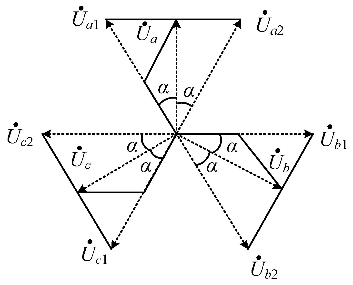
If the phase-shift angle in Figure 2 is changed, the step-up can also be realized. For ease of illustration, all phase-shift angle (which is 15°) in Figure 2 are set as variables α, as shown in Figure 25.
In Figure 25, by increasing α, the output voltage amplitude can be increased, and the step-up effect can also be realized in this way. However, the change of α will cause the change of system harmonic, load voltage ripple coefficient, autotransformer equivalent capacity and IPR equivalent capacity. For the sake of system stability, the step-up phase-shift angle obtained by using the step-up method shown in Figure 25 is generally only one. That is, there is only one step-up ratio considering system stability. This greatly limits the use of autotransformer in step-up occasions. However, the voltage transformation mode proposed in this paper can realize voltage transformation within a certain step-up range according to the needs of voltage transformation occasions, which is more flexible than the voltage transformation mode shown in Figure 25. Table 4 shows the comparison of various transformer step-up structures
As can be seen from Table 4, in addition to the complex manufacturing process of zigzag transformer, due to its own structure with the function of restraining zero sequence current, the system does not need to install zero sequence current suppression devices on the DC side, which can reduce the system volume and save cost compared with other autotransformers. In addition, due to the symmetry of its structure, the AC side of the system using zigzag autotransformer will not produce non characteristic subharmonics. In contrast, zigzag autotransformer is more suitable for step-up than other three transformers mentioned above.
7. Conclusions
In conclusion, the following conclusions can be drawn:
- (1)
- When the transformation ratio of autotransformer is greater than or equal to 1.0353 and less than 2.0705, the equivalent capacity of balance reactor is basically maintained at about 2.017%. At this time, the equivalent capacity of K2 topology transformer is the smallest of the three topologies. Therefore, K2 topology is the best choice among the three topologies.
- (2)
- When the transformation ratio of autotransformer is greater than 2.0705, the equivalent capacity of balance reactor is basically maintained at about 2.017%. At this time, the equivalent capacity of K3 topology transformer is the smallest of the three topologies. Therefore, K3 topology is the best choice among the three topologies.
- (3)
- Compared with the star autotransformer, the DC side of the zigzag autotransformer rectifier circuit presents a high resistance state to the zero-sequence current, which can reduce the use of the DC side zero sequence current suppressor, system complexity and cost of the DC side circuit. Compared with isolated autotransformer, zigzag autotransformer has the advantages of high-power transmission efficiency and small capacity. Finally, for the phase-shifting angle transformer, the voltage step-up range can be expanded by optimizing the structure transformer. To sum up, the zigzag autotransformer step-up topology designed in this paper has the advantages of small volume, low system cost and wide step-up range compared with other step-up structures and step-up methods.
8. Suggestions
In this paper, the winding structure of zigzag autotransformer suitable for step-up is designed, and the selection of phase shift angle and the relationship between step-up ratio and equivalent capacity of key devices are analyzed. The contents to be further explored mainly include:
- (1)
- Research on the transformer structure of other autotransformer structures. There are many kinds of autotransformers, and there are still few studies on step-up and step-down of other autotransformers. Therefore, further exploration is still needed in this regard.
- (2)
- Experimental exploration of theoretical analysis. In the current research, it mainly focuses on its theoretical rationality. The experimental results may not be optimal, but they should be sufficient to draw the conclusions mentioned in the paper. It is necessary to build the corresponding experimental environment to verify the effectiveness of theoretical analysis.
- (3)
- Research on the relationship between transformer with asymmetric structure, transformation ratio and magnetic flux leakage inductance of autotransformer. The current research mainly focuses on the voltage transformation part of the symmetrical autotransformer, but the asymmetric autotransformer structure also exists in the application. At this time, the transformer will have problems such as magnetic flux leakage, inductance leakage and harmonic injection. In this case, it is also necessary to explore the transformation ratio, the harmonic content on the AC side of the system and the equivalent capacity of devices on the DC side of the system.
Author Contributions
Conceptualization, J.W.; methodology, J.W.; software, J.W.; validation, J.W.; formal analysis, J.W.; investigation, J.W.; resources, J.W.; data curation, J.W.; writing—original draft preparation, J.W.; writing—review and editing, J.W. and B.H.; visualization, J.W.; supervision, J.W.; project administration, B.H. All authors have read and agreed to the published version of the manuscript.
Funding
This research received no external funding.
Institutional Review Board Statement
Not applicable.
Informed Consent Statement
Not applicable.
Data Availability Statement
Not applicable.
Acknowledgments
The authors would like to thank the professors for their guidance, the editors for their hard work and the reviewers for their constructive comments.
Conflicts of Interest
The authors declare no conflict of interest.
References
- Abdollahi, R.; Gharehpetian, G.B.; Anvari-Moghaddam, A.; Blaabjerg, F. Pulse Tripling Circuit and Twelve Pulse Rectifier Combination for Sinusoidal Input Current. IEEE Access 2021, 9, 103588–103599. [Google Scholar] [CrossRef]
- Zhang, Y.; Xia, J.; Zhang, X.; Chen, Z.; Li, B.; Luo, Q.; He, Y. Modeling and Prediction of the Reliability Analysis of an 18-Pulse Rectifier Power Supply for Aircraft Based Applications. IEEE Access 2020, 8, 47063–47071. [Google Scholar] [CrossRef]
- Ch, X.-Q.; Hao, C.-L.; Qiu, H.; Li, M. Thirty-six pulse rectifier scheme based on zigzag auto-connected transformer. Arch. Electr. Eng. 2016, 65, 117–132. [Google Scholar]
- Kalpana, R.; Bhuvaneswari, G.; Singh, B.; Singh, S.; Gairola, S. Autoconnected-Transformer-Based 20-Pulse AC–DC Converter for Telecommunication Power Supply. IEEE Trans. Ind. Electron. 2012, 60, 4178–4190. [Google Scholar] [CrossRef]
- Pan, Q.; Ma, W.; Liu, D.; Zhao, Z.; Meng, J. A New Critical Formula and Mathematical Topology of Double-Tap Interphase Reactor in a Six-Phase Tap-Changer Diode Rectifier. IEEE Trans. Ind. Electron. 2007, 54, 479–485. [Google Scholar]
- Abdollahi, R. Pulse doubling in zigzag-connected autotransformer-based 12-pulse ac-dc converter for power quality improvement. J. Electr. Eng. 2012, 63, 357–364. [Google Scholar] [CrossRef] [Green Version]
- Jiang, L.L.; Mao, L.; Chen, Q.H.; Tang, D.P. Design and Optimization of 12 kW P Type 18-pulse autotransformer Rectifier Units. Power Electron. 2012, 46, 4–6. [Google Scholar]
- Chen, J.; Shen, J.; Chen, J.; Shen, P.; Song, Q.; Gong, C. Investigation on the selection and design of step-Up/Down 18-pulse ATRUs for more electric aircrafts. IEEE Trans. Transp. Electrif. 2019, 5, 795–811. [Google Scholar] [CrossRef]
- Fernandes, R.C.; da Silva Oliveira, P.; de Seixas, F.J.M. A family of autoconnected transformers for 12-and 18-pulse converters—Generalization for delta and wye topologies. IEEE Trans. Power Electron. 2010, 26, 2065–2078. [Google Scholar] [CrossRef]
- Abdollahi, R.; Jalilian, A. Application of Pulse Doubling in Star-Connected Autotransformer Based 12-Pulse AC-DC Converter for Power Quality Improvement. World Acad. Sci. Eng. Technol. 2013, 5, 280–288. [Google Scholar]
- Zhang, Y.; Zhang, X.; Chen, Z.; Li, B.; He, Y. Engineering Application Research of Aircraft Power Supply Characteristics Based on 18-Pulse Rectifier Power System. IEEE Access 2019, 7, 22026–22034. [Google Scholar] [CrossRef]
- Xu, Y.; Li, P.; Lu, C.; He, X.; Li, D.; Fang, Y. Waveform Control of Multi-Pulse Flat-Top High Magnetic Field Based on Pulsed Generator System. IEEE Trans. Appl. Supercond. 2020, 30, 1–5. [Google Scholar] [CrossRef]
- Lucia, O.; Maussion, P.; Dede, E.J.; Burdio, J.M. Induction Heating Technology and Its Applications: Past Developments, Current Technology, and Future Challenges. IEEE Trans. Ind. Electron. 2014, 61, 2509–2520. [Google Scholar] [CrossRef] [Green Version]
- Yilmaz, I.; Ermis, M.; Cadirci, I. Medium-Frequency Induction Melting Furnace as a Load on the Power System. IEEE Trans. Ind. Appl. 2011, 48, 1203–1214. [Google Scholar] [CrossRef]
- Perise, J.S.; Bakkar, M.; Rodriguez, S.B. Open-Circuit Fault Diagnosis and Maintenance in Multi-Pulse Parallel and Series TRU Topologies. IEEE Trans. Power Electron. 2020, 35, 10906–10916. [Google Scholar] [CrossRef]
- Singh, B.; Gairola, S.; Singh, B.N.; Chandra, A.; Al-Haddad, K. Multipulse AC–DC converters for improving power quality: A review. IEEE Trans. Power Electron. 2008, 23, 260–281. [Google Scholar] [CrossRef]
- Li, Q.; Meng, F.; Gao, L.; Zhang, H.; Du, Q. A 30-Pulse Rectifier Using Passive Voltage Harmonic Injection Method at DC Link. IEEE Trans. Ind. Electron. 2019, 67, 9273–9291. [Google Scholar] [CrossRef]
- Hao, C.L.; Chen, X.Q.; Qiu, H. Delta-Polygon autotransformer based 24-Pulse rectifier for switching mode power supply. Telkomnika 2016, 14, 431. [Google Scholar] [CrossRef] [Green Version]
- Meng, F.; Gao, L.; Yang, S.; Yang, W. Effect of Phase-Shift Angle on a Delta-Connected Autotransformer Applied to a 12-Pulse Rectifier. IEEE Trans. Ind. Electron. 2015, 62, 4678–4690. [Google Scholar] [CrossRef]
- Burgos, R.; Uan-Zo-li, A.; Lacaux, F.; Roshan, A.; Wang, F.; Boroyevich, D. New step-up and step-down 18-pulse direct asymmetric autotransformer rectifier units. In Proceedings of the 2005 IEEE 36th Power Electronics Specialists Conference, Dresden, Germany, 16 June 2015; pp. 1149–1155. [Google Scholar]
- Xiao-qiang, C.; Hao, Q. Zigzag connected autotransformer-based 24-pulse AC-DC converter. Int. J. Emerg. Electr. Power Syst. 2015, 16, 23–32. [Google Scholar] [CrossRef]
- Singh, B.; Gairola, S. A Zigzag Connected autotransformer Based 24-Pulse AC-DC Converter. J. Electr. Eng. Technol. 2006, 3, 183–187. [Google Scholar]
Figure 1.
Diagram of 12-pulse rectifier based on zigzag autotransformer.
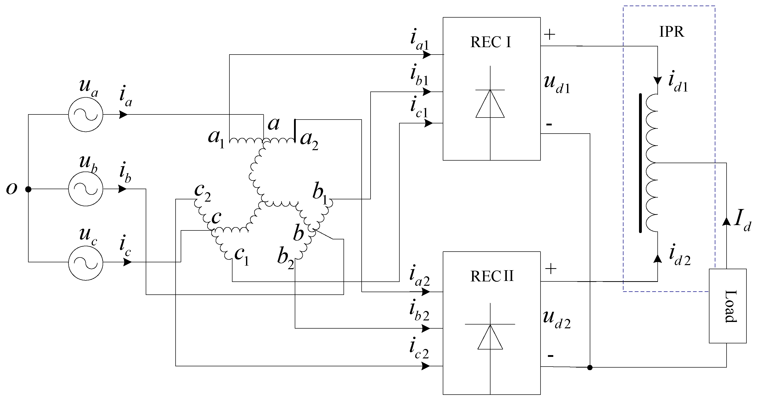
Figure 2.
Phase diagram of zigzag transformer.

Figure 3.
Phase diagram of a set.
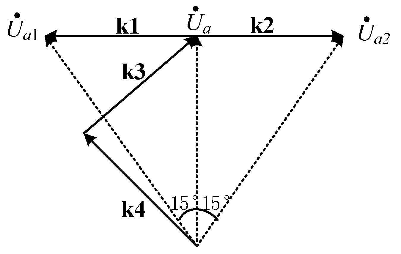
Figure 4.
Diagram of different step-up topologies from phase a: (a) The first design scheme; (b) The second design scheme; (c) The third design scheme; (d) The fourth design scheme.
Figure 4.
Diagram of different step-up topologies from phase a: (a) The first design scheme; (b) The second design scheme; (c) The third design scheme; (d) The fourth design scheme.
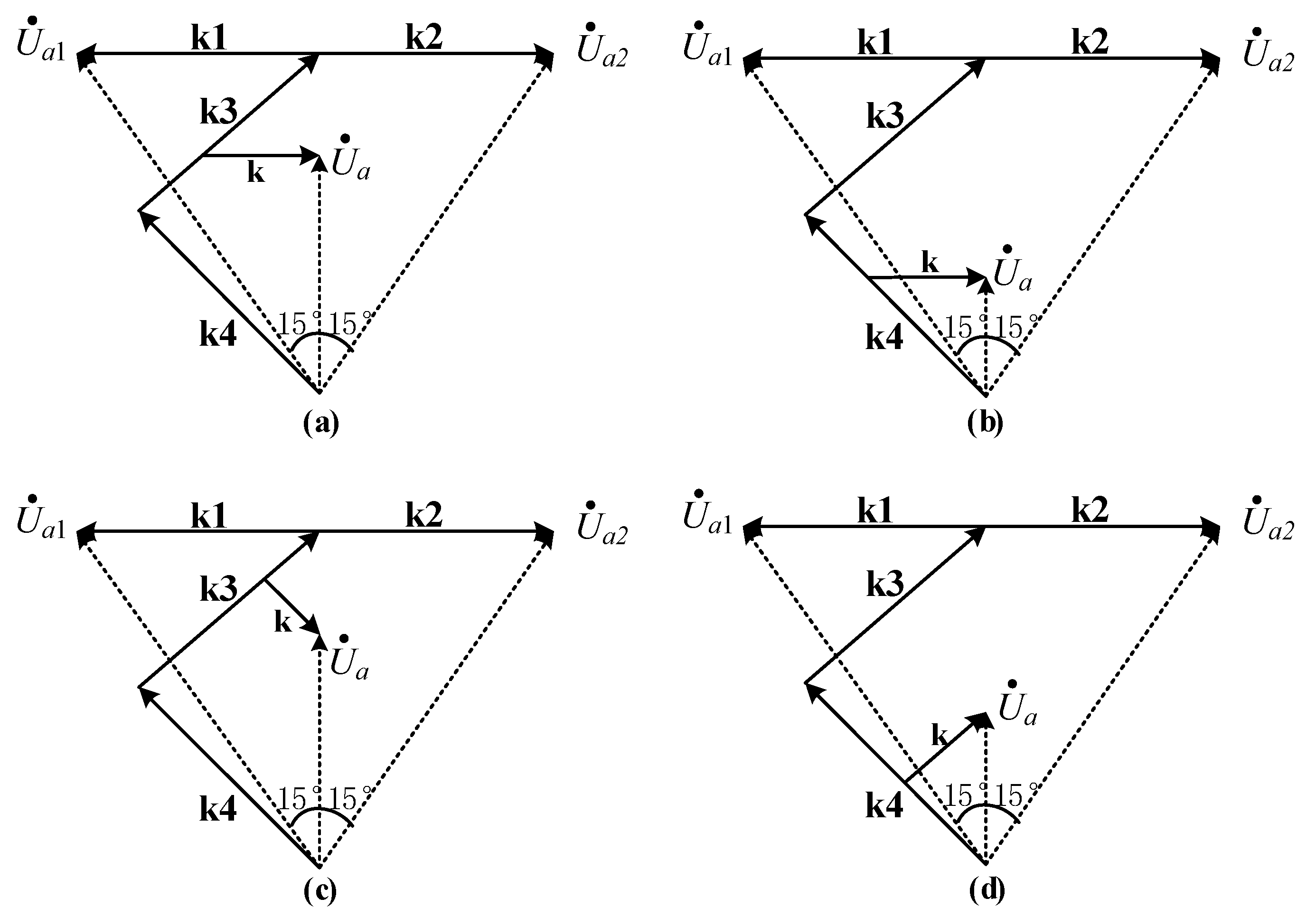
Figure 5.
Phase diagram of intact step-up topologies: (a) The first complete step-up design scheme; (b) The second complete step-up design scheme; (c) The third complete step-up design scheme; (d) The fourth complete step-up design scheme.
Figure 5.
Phase diagram of intact step-up topologies: (a) The first complete step-up design scheme; (b) The second complete step-up design scheme; (c) The third complete step-up design scheme; (d) The fourth complete step-up design scheme.
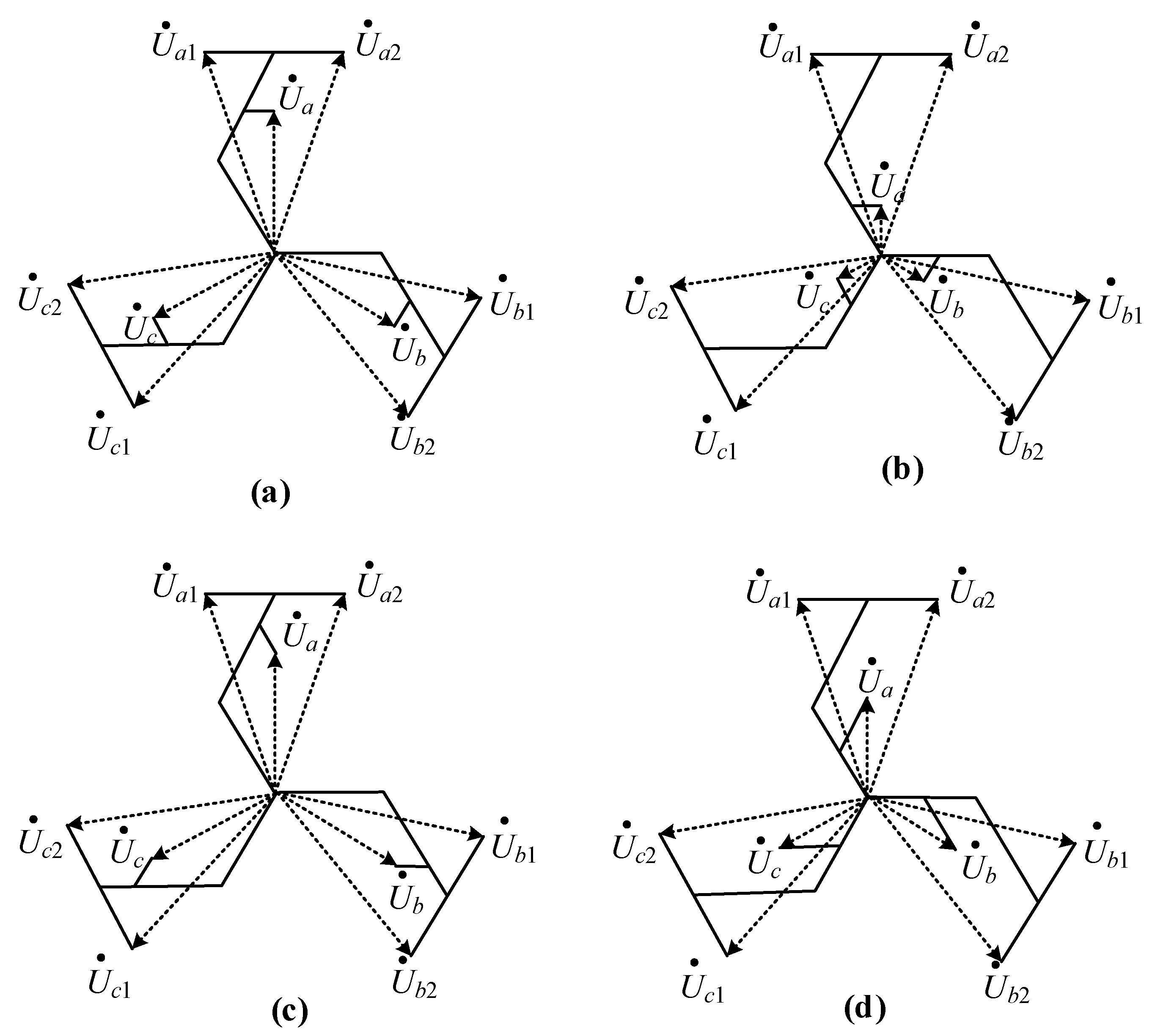
Figure 6.
Diagram of winding configuration of K1 topology when KT between 1.0353 and 2.0705.

Figure 7.
Diagram of winding configuration of K1 topology when KT is greater than 2.0705.
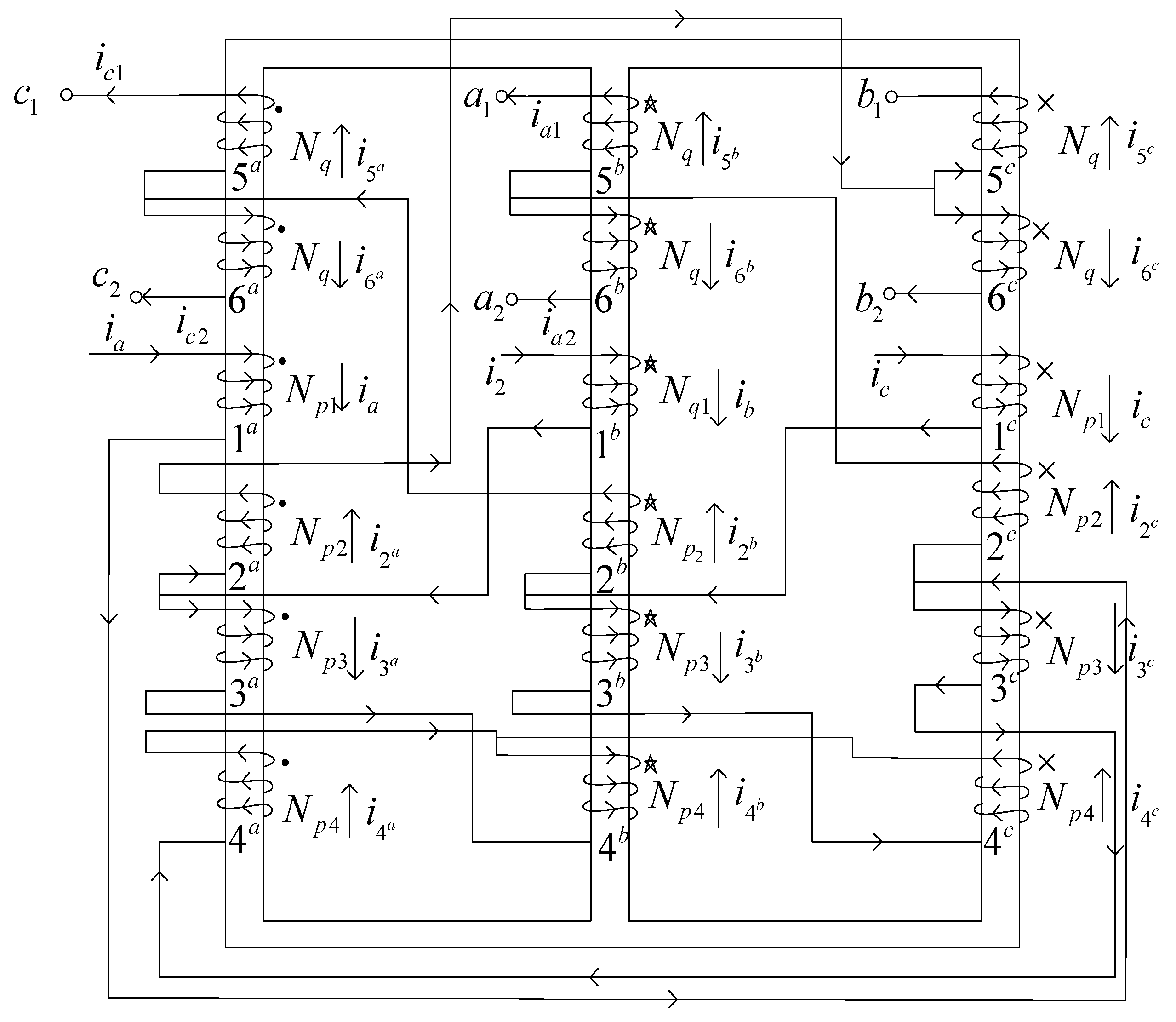
Figure 8.
Detailed phase diagram of a.
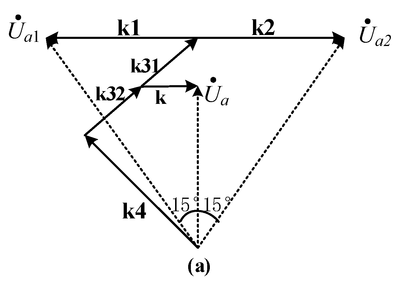
Figure 9.
Flow diagram for Seq of topology K1.

Figure 10.
Effect of KT on Seq of topology K1.
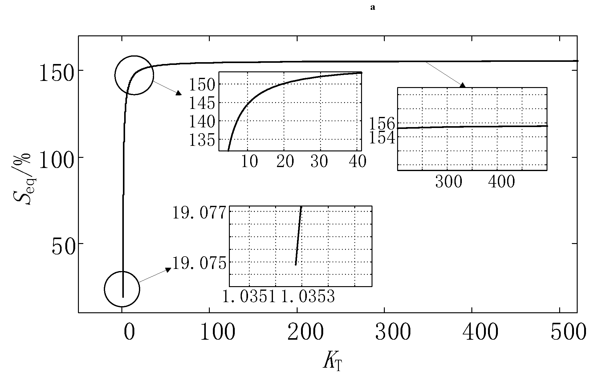
Figure 11.
Diagram of winding configuration of topology K2.
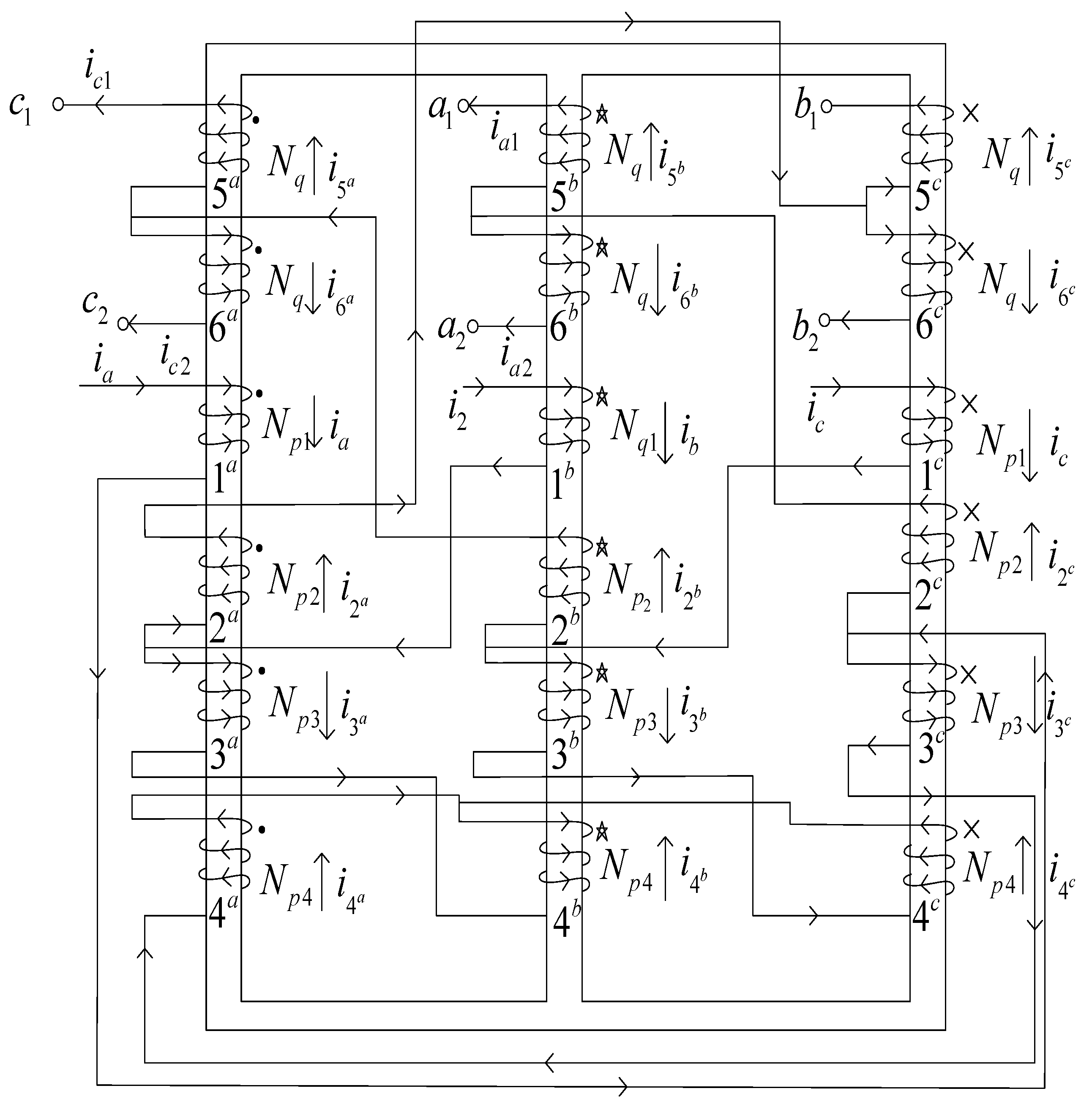
Figure 12.
Diagram of winding configuration of topology K3.
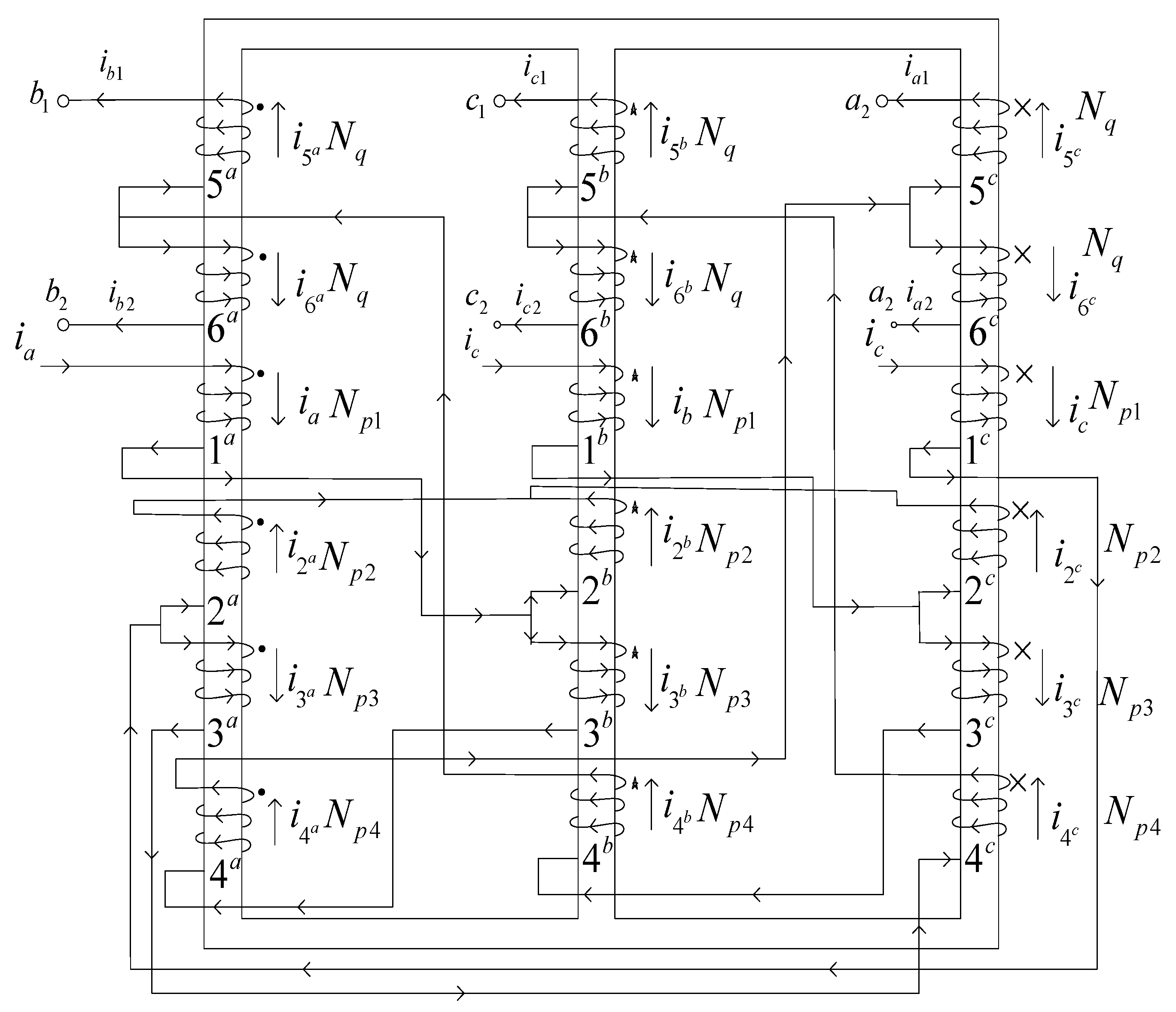
Figure 13.
Effect of KT on Seq of topology K2.

Figure 14.
Effect of KT on Seq of topology K3.
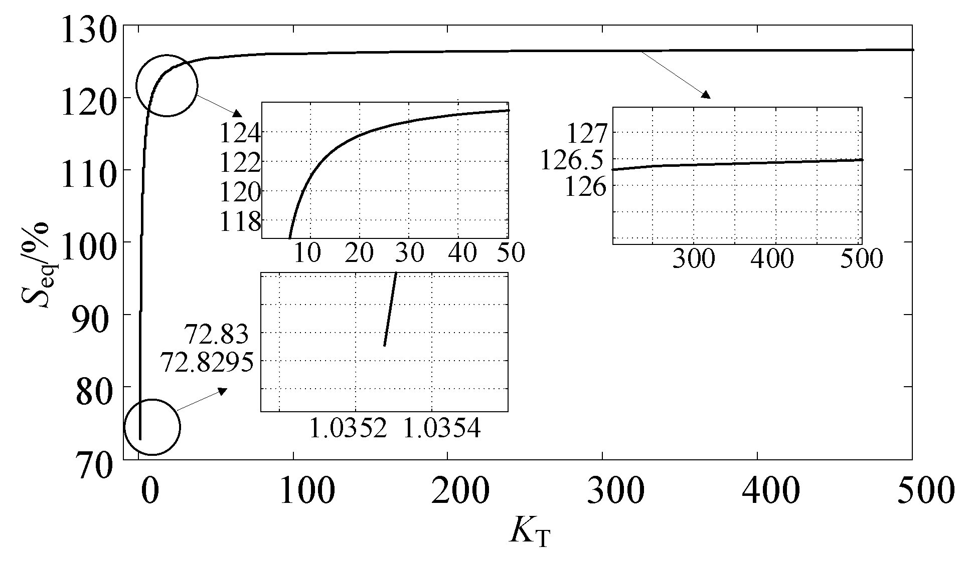
Figure 15.
Effect of KT on Seq of topology K1, K2 and K3: (a) When KT is greater than or equal to 1.0353 and less than 2.0705; (b) When KT is greater than 2.0705.
Figure 15.
Effect of KT on Seq of topology K1, K2 and K3: (a) When KT is greater than or equal to 1.0353 and less than 2.0705; (b) When KT is greater than 2.0705.
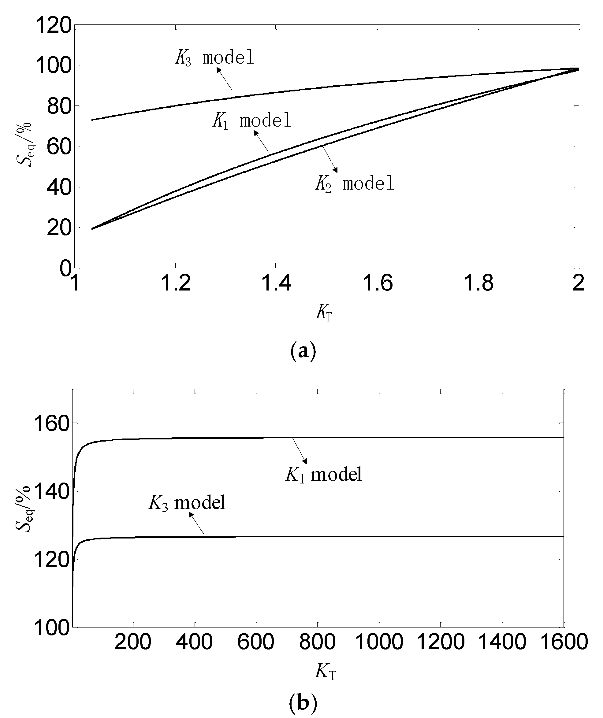
Figure 16.
Flow diagram of SeqIPR.
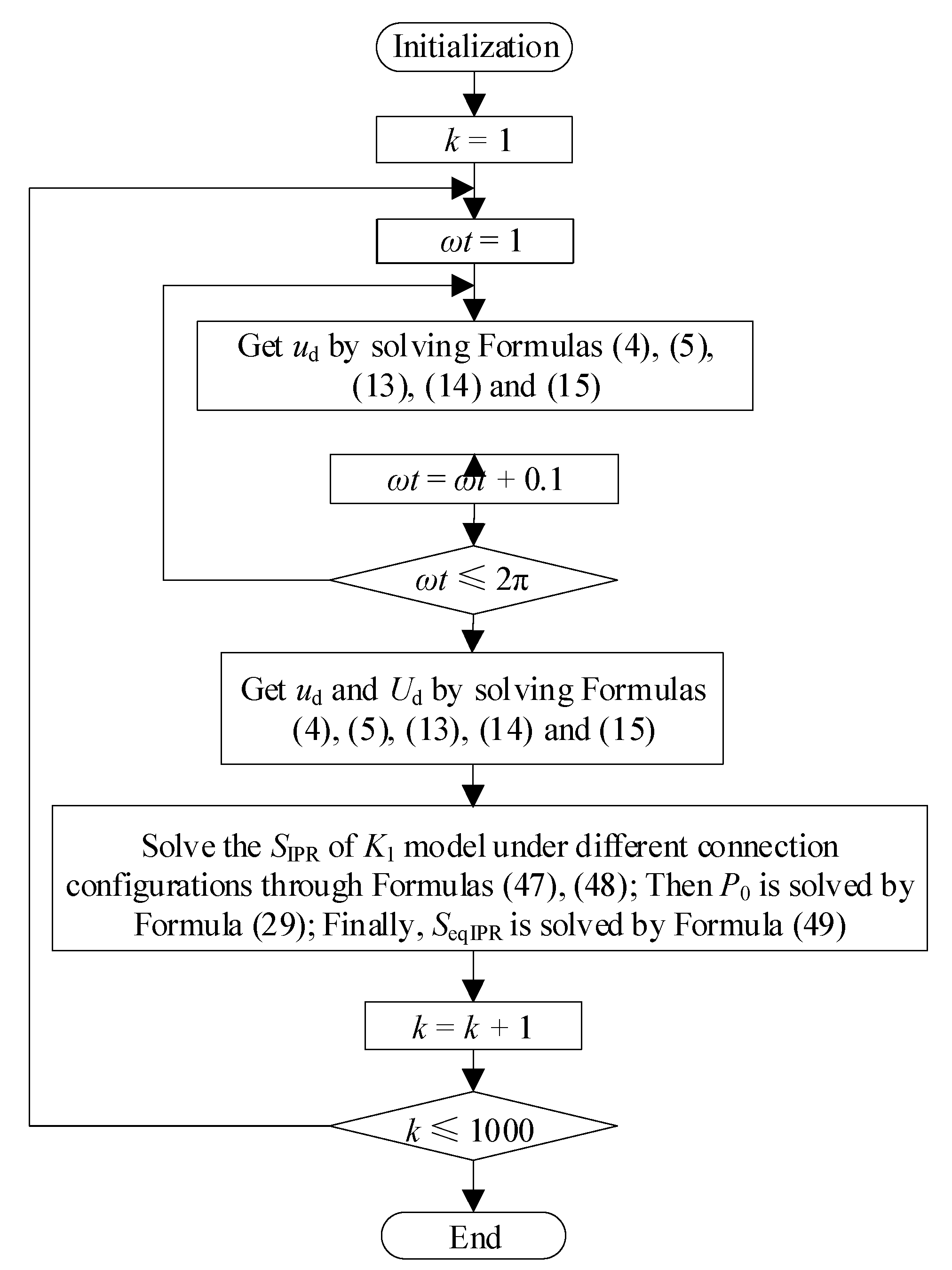
Figure 17.
Effect of KT on SeqIPR of topology K1, K2 and K3.
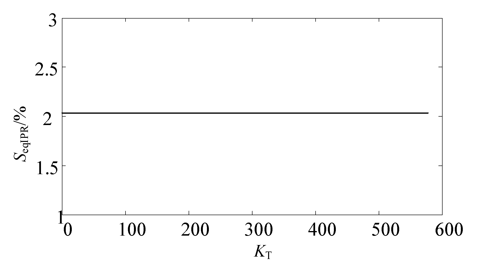
Figure 18.
Diagram of simulation.

Figure 19.
Autotransformer configurations of topology 1–3: (a) Autotransformer configurations for topology 1; (b) Autotransformer configurations for topology 2; (c) Autotransformer configurations for topology 3.
Figure 19.
Autotransformer configurations of topology 1–3: (a) Autotransformer configurations for topology 1; (b) Autotransformer configurations for topology 2; (c) Autotransformer configurations for topology 3.

Figure 20.
Diagram of simulation data and theoretical curve of autotransformer equivalent KVA rating: (a) K1 topology; (b) K2 topology; (c) K3 topology.
Figure 20.
Diagram of simulation data and theoretical curve of autotransformer equivalent KVA rating: (a) K1 topology; (b) K2 topology; (c) K3 topology.

Figure 21.
Diagram of simulation data and theoretical curve of IPR equivalent KVA rating.
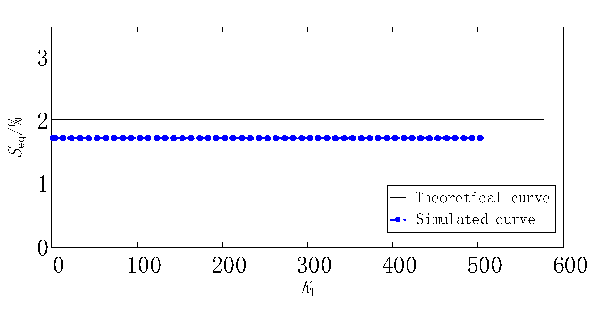
Figure 22.
Phase diagram of star-connected autotransformer.

Figure 23.
Diagram of 12-pulse rectifier with star-connected autotransformer.
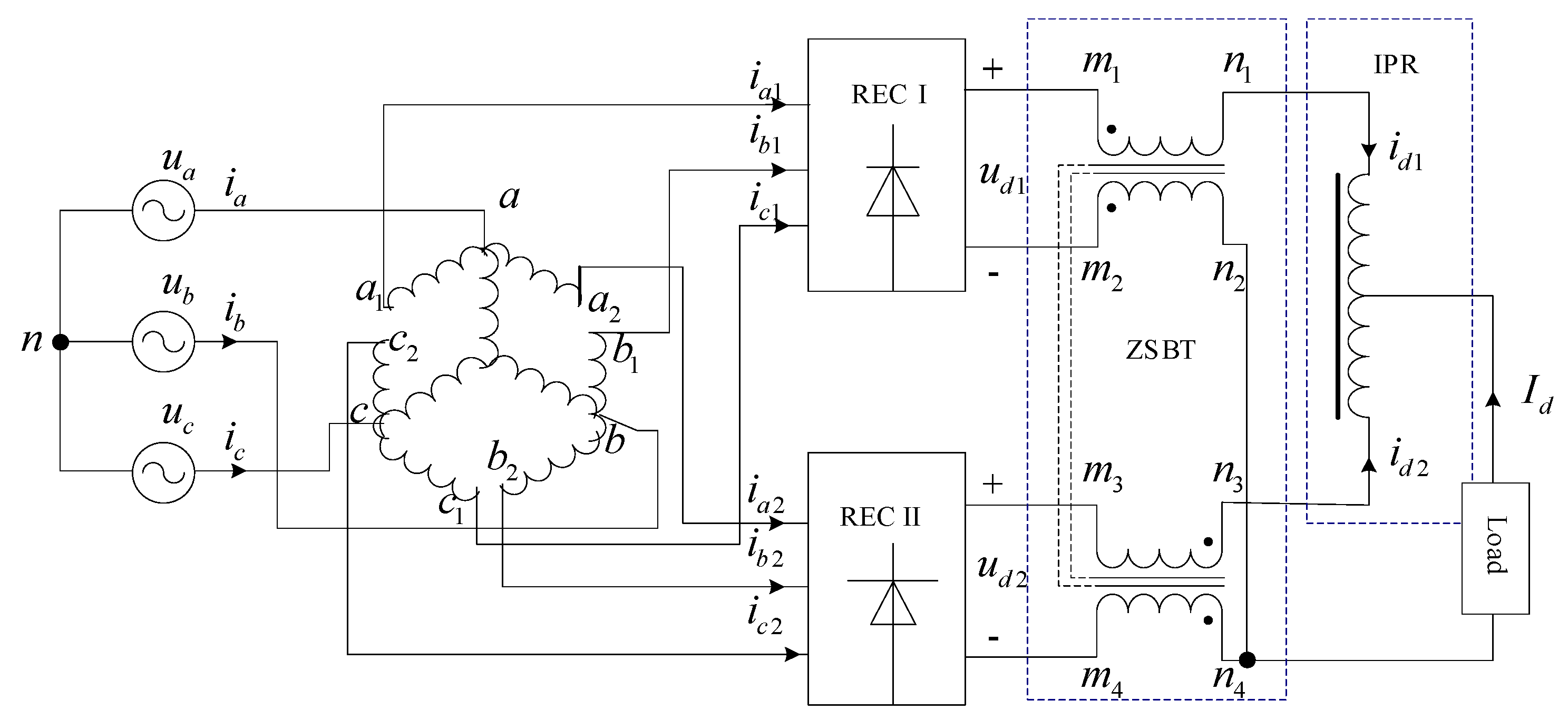
Figure 24.
Diagram of 12-pulse rectifier with isolated transformer.
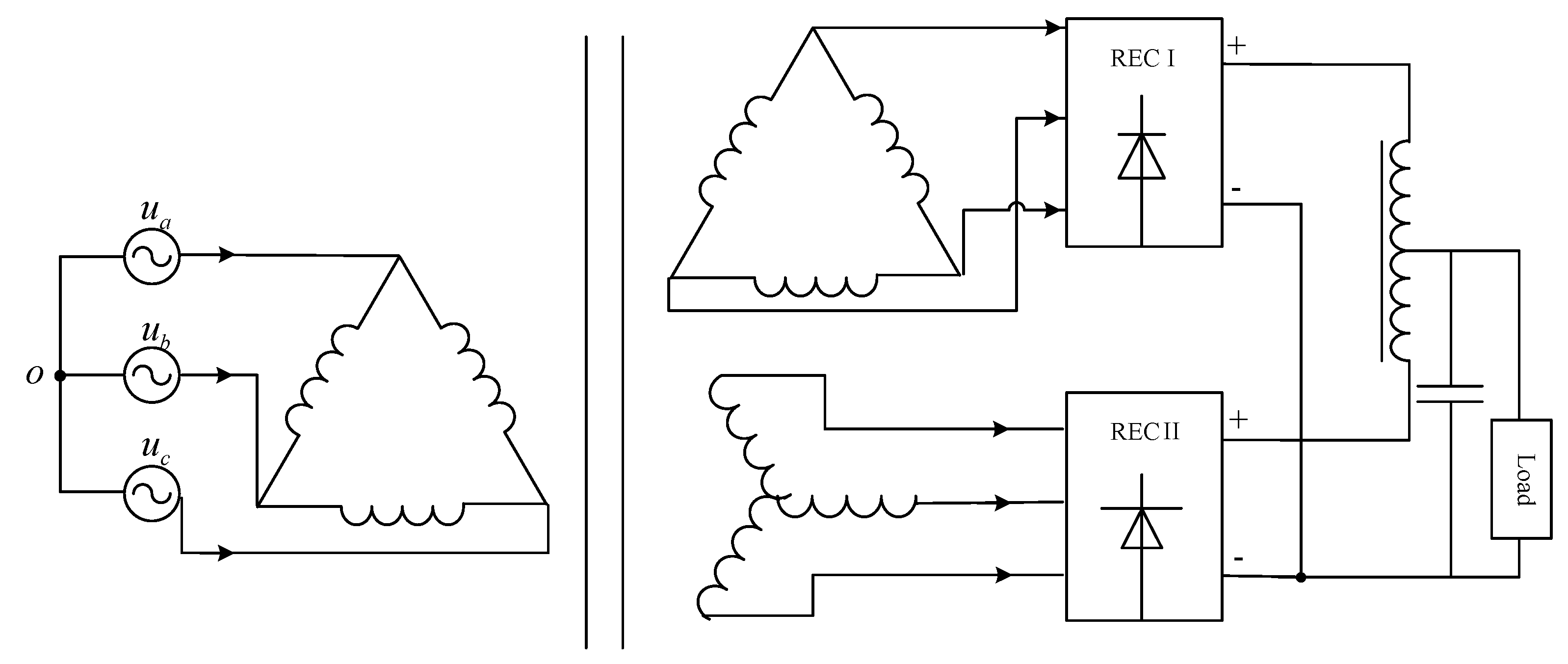
Figure 25.
Phase diagram of zigzag transformer with α.

Table 1.
Parameters of single phase multi winding transformer.
| Units: | pu |
|---|---|
| Nominal power and frequency | [75e3VA, 50 Hz] |
| Winding resistances [R1 R2… Rn] | [0 Ω, 0 Ω, 0 Ω, 0 Ω, 0 Ω] |
| Winding leakage inductances [L1 L2… Ln] | [0 H, 0 H, 0 H, 0 H, 0.00 H] |
| Magnetization resistance Rm | 50 Ω |
| Magnetization inductance Lm | 50 H |
| Saturation characteristic [i1, phi1; i2, phi2;…] | [0, 0, 0.0024, 1.2; 1.0, 1.52] |
Table 2.
Parameters of the universal bridge.
| Number of Bridge Arms: | 3 |
|---|---|
| Snubber resistance Rs | 1 × 10⁵ Ω |
| Snubber capacitance Cs | Inf F |
| Power Electronic device | diodes |
| Ron | 1 × 10⁻³ Ω |
| Lon | 0 H |
| Forward voltage Vf | 0 V |
Table 3.
Parameters of mutual inductance.
| Type of Mutual Inductance: | Two or Three Windings with Equal Mutual Terms |
|---|---|
| Winding 1 self-impedance [R1 L1]: | [0.7 Ω 0.7 × 10⁻³ H] |
| Winding 2 self-impedance [R2 L2]: | [0.7 Ω 0.7 × 10⁻³ H] |
| Mutual impedance [Rm Lm]: | [1.0 Ω 1.0 × 10⁻³ H] |
Table 4.
Comparison of step-up transformers.
| Step-Up Structure | Blocking Zero Sequence Current | Manufacturing Difficulty | Transformer Symmetry | Will Non Characteristic Harmonics Be Generated |
|---|---|---|---|---|
| Star connected autotransformer | No | High | Symmetrical structure | No |
| Isolated transformer | No | Low | Asymmetric structure | Yes |
| Phase shift angle transformer | No | High | Asymmetric structure | Yes |
| Zigzag autotransformer | Yes | High | Symmetrical structure | No |
Publisher’s Note: MDPI stays neutral with regard to jurisdictional claims in published maps and institutional affiliations. |
© 2021 by the authors. Licensee MDPI, Basel, Switzerland. This article is an open access article distributed under the terms and conditions of the Creative Commons Attribution (CC BY) license (https://creativecommons.org/licenses/by/4.0/).
Share and Cite
MDPI and ACS Style
Wang, J.; He, B. Novel Step-Up Topologies of Zigzag Autotransformer. Electronics 2021, 10, 3071. https://doi.org/10.3390/electronics10243071
AMA Style
Wang J, He B. Novel Step-Up Topologies of Zigzag Autotransformer. Electronics. 2021; 10(24):3071. https://doi.org/10.3390/electronics10243071
Chicago/Turabian StyleWang, Jiarong, and Bo He. 2021. "Novel Step-Up Topologies of Zigzag Autotransformer" Electronics 10, no. 24: 3071. https://doi.org/10.3390/electronics10243071
Note that from the first issue of 2016, this journal uses article numbers instead of page numbers. See further details here.