Abstract
This paper presents a new hardware reconfiguration approach named hardware reconfiguration through digital television (HARD), which can update FPGA hardware modules based on digital TV (DTV) signals. Such a scheme allows several synthesized hardware cores (bitstreams) signaled and broadcast through open DTV signals via data streaming to be identified, acquired, decoded, and then used for system updates. Reconfiguration data are partitioned, encapsulated into private sections, and then sent in a carrousel fashion in order to be recovered by modified receivers. Service information content, specially designed for identifying and describing the characteristics of multiplexed hardware bitstreams, was added to the transmitted signal and provided all necessary information in the traditional DTV style. The receiver framework, in turn, checked whether those characteristics corresponded to its embedded reconfigurable devices and, if a match was found, it reassembled the related bitstreams and reconfigured the respective internal circuits. Experiments performed with an implementation of the proposed methodology confirmed its feasibility and showed that remounting and reconfiguration times were satisfactory and presented no blocking aspect. Finally, HARD can be used in several designs regarding intelligent reconfigurable devices, minimize device costs in the long term, and provide better hardware reuse.
1. Introduction
Embedded systems and digital TV (DTV) receivers are designed with no concern for technology advancements regarding computational tasks performed by hardware over time. Such systems typically have several functions performed with silicon hardware (application-specific integrated circuit (ASIC)) due to demands for high computational complexity. One example is video decoding (e.g., advanced video coding (AVC) or AVC/H.264 [1]), a demanding task customarily performed by ASIC silicon devices.
Typically, when a new DTV network is deployed, ASIC devices are then used for developing new receivers, which provide all necessary decoding and processing techniques. Nonetheless, suppose the associated standards are revised, and other algorithms or protocols are adopted. In that case, the current devices must be replaced, which are commonly known as legacy hardware and are closely related to ASICs.
Recently, the international telecommunications union (ITU) introduced high-efficiency video coding (HEVC) [2,3,4] as the next-generation video compression standard. Compared with its predecessor (MPEG-4 AVC/H.264), it presents about twice the compression efficiency without deteriorating the quality level of the encoded signals [5,6].
Given what was presented, one may notice that AVC/H.264-based systems cannot immediately incorporate the benefits of HEVC due to legacy hardware. However, such flexibility could be achieved if DTV receivers could perform tasks through reconfigurable devices (e.g., a field-programmable gate array (FPGA)) instead of ASICs.
Currently, the semiconductor industry and open core communities have boosted the use of FPGAs. It is worth noticing that they even provide hardware description source codes (e.g., VHSIC hardware description language (VHDL) [7] and Verilog [8]) for many applications (e.g., crypto cores, DSP cores, and encoder/decoder cores), which are available for download and immediate use in project solutions [9]. Depending on the target market, current FPGA technologies are already a good option. The main reason for this is the amortization of non-recurring engineering (NRE) costs among customers for each integrated circuit (IC) family [10,11,12]. Finally, such devices can even be used for implementing entire systems [13,14].
In addition, specifically regarding the pay TV market, FPGA solutions are already very interesting and present some advantages. As cable and satellite operators must provide devices to all subscribers to offer services in vertical markets, technology advancements usually result in new receivers. Consequently, the proposed approach could decrease the costs necessary for maintaining existing consumers in the long run, since updating receivers may be cheaper than replacing them. Aside from that, this also aligns with the fast development and deployment cycles currently seen in the DTV world, while the legacy hardware problem is also alleviated. Consequently, the possibility of reconfigurable hardware platforms becomes appealing and may devise new directions regarding DTV receiver design.
The presented observations are the inspiration for the present work, which proposes a new approach for hardware updates with DTV signals as the transport infrastructure, named hardware reconfiguration through digital television (HARD). In the context of a DTV system, the reconfiguration bitstream can be regarded as a regular data broadcast along with a high-definition television (HDTV) program, as shown in Figure 1.
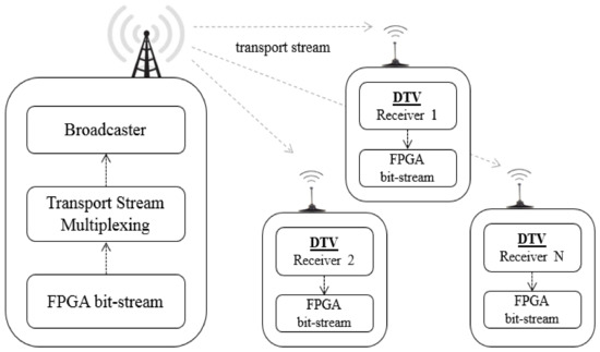
Figure 1.
FPGA bitstream broadcast in a DTV environment.
A DTV system comprises several subsystems, including data preparation for transmission, complete signal reception, and subsequent content filtering. In the transport stream (TS) step, audio, video, and data, including FPGA bitstreams, are interleaved, engendering a multiplexed DTV streamflow [15].
Finally, in the transmission step, the resulting signal is modulated and sent through a DTV channel. At the receiving side, each device in range detects and decodes the transmitted content. Such a process results in the complete extraction of the FPGA core data stream, which is then reassembled in a persistent storage module. After this step, the FPGA module is reconfigured.
This work deals with a generic hardware update in DTV environments, where receivers do not need to leave the user’s premises and extend DTV channels by introducing a way of transmitting synthesized hardware data. It can be employed in a wide range of future designs regarding intelligent hardware architectures, and it can boost the use of hardware reconfiguration in embedded solutions (e.g., DTV receivers).
Hardware reconfiguration has already been used in many projects, but the solution presented here is innovative for performing such a process. It is expected that the subject of this work, along with its related schema, can stimulate the scientific community to develop a wide range of environments which rely on hardware update technologies.
2. Related Work
The usage of FPGA-based systems in the telecommunication industry is widespread, with typical applications in the development of general transmission decoders [16,17], video decoders [18,19], security approaches like parity checks [20,21], satellite issues [22,23], and digital TV systems [24]. The modern usage of those devices includes machine learning proposals [25], cloud computing [26], and 5G communication networks [27].
Recent studies presented related work based on intelligent hardware architectures, with hardware reconfiguration as a core technology to build more compact and efficient systems. Indeed, structures with hardware resource management are compelling solutions for embedded and discrete event systems [28,29].
In many approaches, pre-synthesized hardware unit functions can execute runtime reconfiguration of FPGA cores according to user interaction [15,30]. The mentioned work presented a hybrid architecture that used a CPU and a reconfigurable device (FPGA) for performing tasks controlled by a resource manager, which used a decision algorithm to choose among pre-synthesized hardware cores or software modules [31]. When the mentioned resource manager indicated the use of a hardware module, its FPGA was reconfigured; otherwise, a software module was run by the CPU and performed the desired task. In other words, in those works, a good splitting algorithm of the system into the dynamic (reconfigurable) and static (non-reconfigurable) partitions is proposed [32,33].
Intelligent embedded systems can make use of partial dynamic hardware for runtime reconfiguration. Like a microprocessor multi-task system, such a feature allows a multiplex of distinct hardware modules to run simultaneously. Thus, functional pre-synthesized hardware blocks (i.e., logical blocks) can be reconfigured or not reconfigured according to the system’s needs [34,35]. The associated system architecture is coordinated by a microcontroller device in charge of reconfiguring the pre-synthesized hardware blocks in FPGA devices [36]. Aside from that, a list of pre-synthesized hardware blocks is kept in flash memory. This way, the use of partial dynamic reconfiguration causes a considerable reduction in power consumption [37], in addition to a significant decrease in device costs [38].
The reconfigurable architecture presented by Hillenbrand et al. [39] allowed the inclusion of signal-processing pre-synthesized cores into hardware description language (HDL) sources to be runtime reconfigurable. This feature is significant, considering that state-of-the-art FPGA devices require large amounts of time and memory for their compilation processes. In those cases, pre-synthesized cores minimize the synthesis processes and allow the design of adaptive reconfigurable system architectures.
A complete multicore reconfigurable platform can provide a rich and flexible environment for application programmers [40]. Each processor core has a coupled reconfigurable coprocessor unit in that architecture, which allows the extension of a processor’s instruction set to run applications.
A streaming-based partially reconfigurable architecture and programming model may be used to simplify the development of streaming applications. Thus, programmers could describe such operations with a suitable software/hardware multithread model. The efficiency presented by such a reconfigurable architecture demonstrates that its power efficiency is much better than that of state-of-the-art graphics processing units [41].
The presented related works are based on pre-synthesized cores, which must be present on their embedded file systems. Those modules are used according to system demands for updating several devices or even due to user interaction. However, HARD is based on broadcast networks, through which pre-synthesized cores can be sent. Therefore, several core modules from different manufacturers can be delivered simultaneously to a large number of receivers.
3. Hardware Data Broadcast through a Digital TV Signal
DTV TSs consist of packets with audio, video, and data and are 188 bytes in length. TS packets are the basic TS data unit. They are composed of a sync byte field whose value is 0x47, followed by 3 1-bit fields—a transport error indicator, payload unit start indicator, and transport priority—and an identification (13-bit), known as a packet identifier (PID) [42], among other aspects. The PID information provides a means of differentiating payload content regarding distinct transport units (packets) in a TS. If a PID is allocated and reported to a receiver (through a table), that means a given packet carries video, audio, or other data, according to what was informed. Thus, the broadcast content is identified by its respective PID value. Aside from that, the field transport error indicator can be used for indicating a packet that contains at least one uncorrectable bit error, which may lead an application to discard it, avoiding the use of corrupted data.
Figure 2 represents a transport stream with different packets consisting of video, audio, program association table (PAT) sections, and hardware payload (PID 0x77). This transport stream slice shows that packets with the same PID and carrying parts of the same information are spaced over time. Demultiplexers then need to filter a transport stream, using the corresponding PIDs for accessing its payload content.
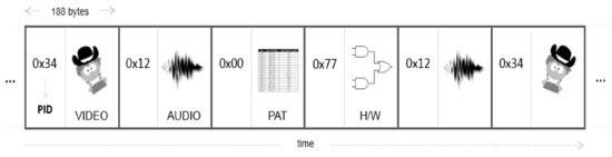
Figure 2.
Transport stream packet structure used to carry different data types, which include hardware reconfiguration data.
DTV systems can broadcast binary applications [42] interleaved with other HDTV contents (e.g., audio, video, and data). To inform that an application is being broadcasted, a DTV standard employs the application information table (AIT) [43], which the receiver resident system then uses to download all content related to that same application.
DTV telecommunication networks allow the broadcasting of several data types. Here, it is essential to consider two main features: the data format and the required synchronization, which are necessary for broadcasting some data types. The formats may be classified into delimited data, un-delimited data, and datagrams following some protocol. Delimited data can be divided into units of predefined size (e.g., files and objects). However, un-delimited data are considered continuous bitstreams. Finally, datagrams correspond to data packets related to a communication protocol (e.g., IPv4 and IPv6).
Regarding synchronization, the transmitted data are divided into synchronous, synchronized, and asynchronous [44]. Synchronous data have synchronization requirements with other data in the same stream, known as intramedia synchronization. Synchronized data must be presented at predetermined time instances and synchronized with elements of different media (e.g., closed captions), which is called intermedia synchronization. Finally, asynchronous data, in turn, have no temporal synchronization requirements.
The data format characteristics and the required data synchronization are important when choosing the best data broadcasting method.
3.1. Data Broadcasting Mechanisms
An essential feature of DTV standards is data broadcasting capability. Broadcast data are generally used to describe and identify the HDTV broadcast content. For instance, the European DTV standard, known as digital video broadcasting (DVB), offers four data transport mechanisms: data piping, data streaming, multiprotocol encapsulation (MPE), and carousels [45,46].
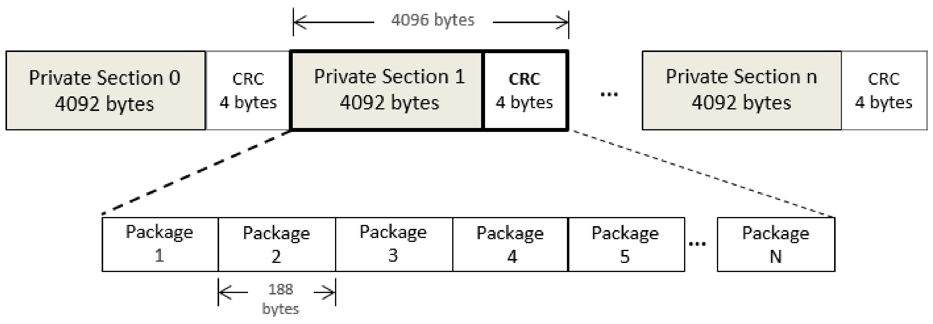
Data piping is the most straightforward mechanism, which consists of inserting raw data directly into the TS packet payload areas. Data streaming is more complex when compared with data piping and can arrange data using private sections [42] or packetized elementary stream (PES) packets. Private sections can be split into units of at most 4084 bytes of payload (actually, it presents a variable-length; see field private_section_length in Table 1), plus 8 header bytes and 4 bytes of a cyclic redundancy check (CRC), which amounts to 4096 bytes. Some advantages of private sections are contiguity control, given by the section number field, and error detection control, obtained via redundant information (e.g., CRC_32) [47].
That being said, it is worth noticing that receivers can use field CRC_32 to detect corrupted sections, which confers safety and avoids using erroneous data. This way, when corrupted sections are identified, receivers can choose to discard those and then wait for the next ones, as this kind of mechanism is usually employed for sending data in repeating cycles. Consequently, any data reception procedure is concluded only when all sections with correct CRC_32 fields are obtained, which results in a reliable channel.
Reimers, for instance, describes the data streaming method by PES packets [48]. MPE uses the logical link control subnetwork access protocol (LLC/SNAP) encapsulation, which allows the use of any network protocol, in addition to unicast (i.e., datagram sent to a single receiver) and multicast (i.e., datagram sent to receiver sets).
Carousels are techniques used to deliver data in a continuous cycle [49,50], as defined by the digital storage media command and control (DSM-CC) standard [51,52], which is adopted by both the Digital Audio Video Council (DAVIC) and DVB repeatedly. DSM-CC specifies two types of carousels: data and object carousels. The latter extends the data carousel by setting a file system directory structure (e.g., media files, applications, image files, and directories).
Section 5.1 addresses the presented broadcasting methods by evaluating the core data characteristics and the most suitable approach to implement hardware reconfiguration schemes.
4. DTV–Receiver Architectures and FPGA Reconfiguration Schemes
DTV receivers (e.g., set-top boxes) are used to demodulate and decode the HDTV broadcast signal to recover the transmitted TSs carrying audio, video, and data packets (see Section 3). Typically, DTV standards specify reference receiver architectures to suggest design implementations to manufacturers [53]. Commercially available receivers usually present similar compositions and provide a set of device drivers with exemplary applications, which are taken as a reference to access and manipulate hardware devices.
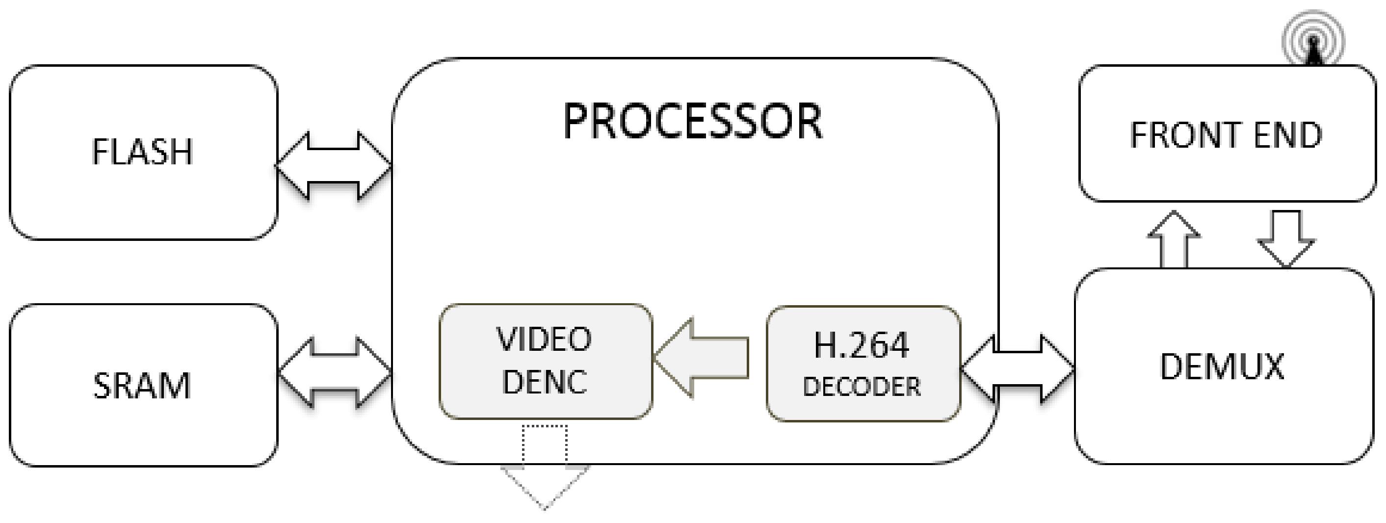
Figure 3 shows the necessary components present in receiver architectures. The air interface (e.g., frontend, also called a network interface module) device is responsible for demodulating any available DTV signal. It recovers the TS stream flows output by multiplexers, which were sent by DTV transmitters. The DEMUX component uses the frontend’s (air interface) output (transport streamflow), filters packets related to a given PID identifier (see Section 3), and outputs them in separate continuous flows. Later, those flows are forwarded to their respective decoders (e.g., H.264 video decoder), which in turn decode the content (e.g., audio or video packets) in a continuous process. Finally, the information delivered by the video decoder is passed to its respective digital video encoder (DENC) module. The next step converts digital baseband video data into analog signals (e.g., Y/C and composite video broadcast signals) to provide a video interface with other equipment (e.g., TV sets and personal video recorders). The other flows present in transport streams are also filtered by DEMUX, according to DTV tables or a given PID provided by resident applications (e.g., filter software parser) for control.
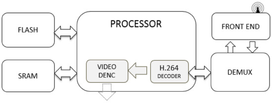
Figure 3.
Receiver architecture comprises an air interface (frontend), demultiplexer, H.264 decoder, and memory.
4.1. FPGA Stand-Alone Reconfiguration Schemes
The standard hardware development process begins with a design entry (e.g., hardware schematics or HDL) [54]. Then, an HDL is used to develop hardware specifications to configure an FPGA or a complex programmable logic device (CPLD). The most well-known HDLs are VHDL and Verilog. In the final step of standard design flows, a bitstream file (e.g., raw binary file (RBF)) is generated and then used to reconfigure an FPGA device. Typically, this is performed by an electronic design automation (EDA) tool, which is also provided by FPGA manufacturers [54]. Thus, it is possible to validate final design behaviors before delivering bitstreams.
On the one hand, FPGA reconfiguration is typically performed with a tool provided by the hardware manufacturer. On the other hand, users may also develop it in a stand-alone reconfiguration scheme. In general, stand-alone strategies employ two modes (e.g., master or slave mode) to reconfigure FPGAs using a bitstream (pre-synthesized binary code). In master mode, an FPGA is typically used to control a reconfiguration process. However, in slave mode, FPGA configuration is controlled by an external device (e.g., a microcontroller, CPLD, or another FPGA). Additionally, the standard IEEE 1149:1 [55], a joint test action group (JTAG), is another mode commonly used by FPGA manufacturers. Typically, the latter provides a JTAG cable and a programming tool, which are used to reconfigure their FPGA development boards. Those cables can work with different communication interfaces, such as USB, parallel or serial ports, or ethernet. They are an attractive way to construct a host/target communication interface, which has been commonly adopted by several embedded systems and already largely tested and validated. JTAG has four control signals—test data input, test data output, test mode selects, and test clock—which are used to configure devices through a test access port controller [55].
The available literature also presents stand-alone open-source JTAG libraries [56,57], which enable a variety of JTAG-based manufacturer communication cables. Those libraries can use the serial vector format (SVF) [58] to configure several FPGA models. SVF files, which describe actions over JTAG interfaces, are standard for exchanging descriptions of high-level IEEE 1149.1 (JTAG) bus operations [58]. Then, a stand-alone program can parse and play an SVF file, thus reconfiguring an FPGA.
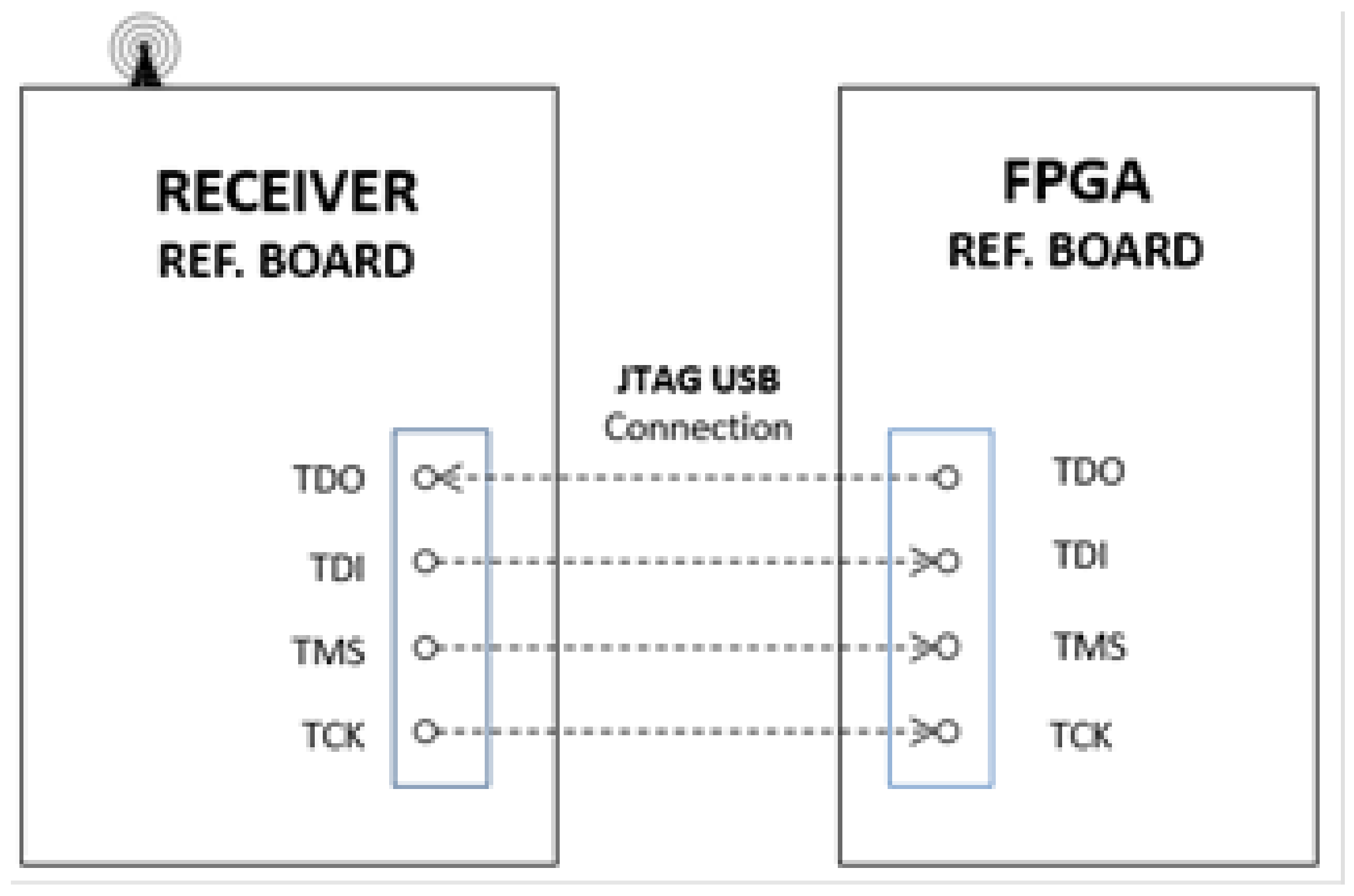
SVF files can be obtained from other formats through a converting tool or even an FPGA manufacturer tool. Indeed, most FPGA manufacturers commonly provide this file, used as a standard format to reconfigure devices. A reference DTV receiver was used as a host device and a commercial FPGA board as a target device to create a host/target physical connection. Based on the JTAG program mode, the USB manufacturer’s programmer cable connects both sides, as seen in Figure 4.

Figure 4.
DTV Receiver (host) connected to a reference FPGA board (target) through a USB/JTAG programmer cable.
The stand-alone FPGA programming system was based on an open-source JTAG reference code adapted to fit the chosen DTV receiver (i.e., the module responsible for reconfiguring the FPGA). Some third-party libraries were integrated into the receiving system so that the open-source code could work properly. Therefore, a resident application (reconfiguration module) becomes able to control the FPGA board’s read and write (R/W) operations.
5. The Proposed Hardware Reconfiguration Scheme Based on the DTV Signals
The entire hardware reconfiguration scheme can be split into three distinct steps. The first one consists of preparing the data to be broadcast. In particular, that means encapsulating synthesized FPGA bitstreams into TSs. Here, one assumes that a bitstream is already synthesized, tested, and validated for the same FPGA model used by a receiver. The second step involves filtering, remounting, checksum validation, and persistence. Finally, the last one uses downloaded bitstreams to reconfigure a receiver’s FPGA module. The following sections discuss each step of this procedure in detail.
5.1. Encapsulating Hardware Data
To choose a transmission method for hardware reconfiguration modules, one must consider the data format and timing requirements. Regarding the data format, as already mentioned, the possible classifications are delimited, undelimited, and datagrams. When addressing the timing requirements, data can be synchronous, synchronized, and asynchronous. Table 1 summarizes what was tackled in this work regarding the data broadcasting mechanisms presented in Section 3.1.

Table 1.
Comparison regarding data broadcasting methods.
Ultimately, hardware cores are binary data, which contain bitstreams for configuring FPGA devices. As a result, hardware reconfiguration streams are delimited data, and they are split into slices of a predetermined size. Moreover, they do not have temporal requirements and can be considered as asynchronous data.
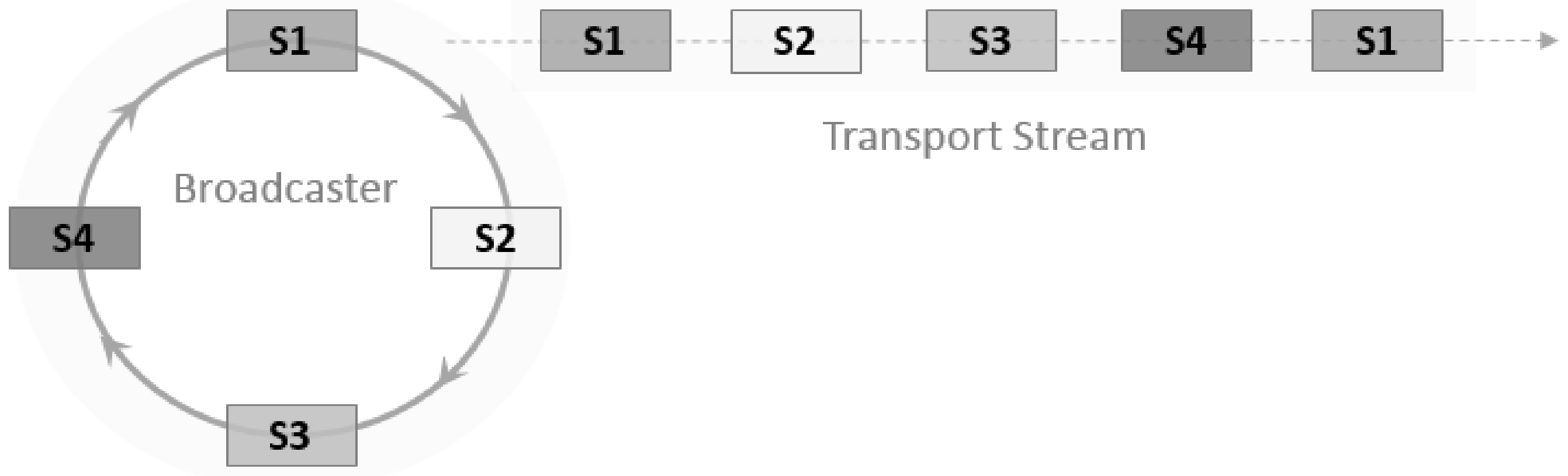
Indeed, the great concern lies in the data recovery procedure, which must be reliable and provide an error-detecting capability [48]. There is infrastructure regarding data recovery through carousels [45,46]. However, they use complex structures, which incur a significant overhead and high computational effort due to its dependence on a network protocol and data piping providing synchronization capability. Aside from that, hardware reconfiguration files are not complex, which suggests simple transport mechanisms. Therefore, a good option is data streaming through private sections, which is simple and already provides error detection tools and support to delimited and asynchronous data, with structures less complex than those used in carousels. In summary, the reconfiguration file can be partitioned into sections, enumerated according to their insertion order, and cyclically repeated as shown in Figure 5.

Figure 5.
Transmission strategy with private sections.
5.2. Hardware Data Multiplexing in Transport Streams
From the point of view of DTV signals, FPGA bitstreams are seen as regular data. Thus, such content needs to be signaled (i.e., with a PID to identify a stream and a new data table) to notify receivers about its existence in a broadcast signal, aside from following a DTV system’s rules. First, it is necessary to choose a suitable method for transporting reconfiguration bitstreams by considering their main characteristics. This step was already conducted above and resulted in data streaming through private sections (see Section 5.1), whose syntax is shown in Table 2 [42] (reproduced here for convenience). It is worth noticing that its mnemonics are defined in the standard MPEG-2 systems.
Table 2.
Syntax of private sections.
Thus, according to data streaming’s rules, a hardware bitstream must be divided into private chunks 4092 bytes in length (including the header), as illustrated in Figure 6. In Table 2, identification of the private section content identification is given by table_id, an 8-bit field of private_section(), while section_number presents the sequential number, which is used to keep the correct order for data remounting. It is worth noticing that sections can arrive out of order. Therefore, resident receiver systems must implement a mechanism to maintain the correct section order.
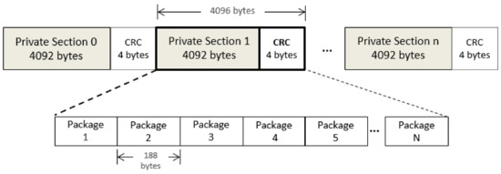
Figure 6.
The FPGA reconfiguration bitstream is divided into sequenced private sections, which are then organized into TS packets.
The field last_section_number indicates the total number of sections used for carrying synthesized hardware content. At the same time, private_data_byte informs about the number of bytes transmitted according to a predefined format, which is used to bear an FPGA bitstream. For this work, section_syntax_indicator was set to “1” to enable CRC_32 checksum validation for the private section syntax, allowing the receivers to detect errors through a checksum algorithm (see Section 3.1).
To signal the FPGA bitstream content, HARD follows a syntax similar to the one used by AIT. In summary, it must provide an FPGA bitstream description and an access point so that the receivers can download and remount the FPGA core data. This new table, named the update information table (UIT), follows the AIT’s syntax and intends to provide detailed information about the characteristics of transmitted FPGA cores. This is crucial information used by receivers to decide if transmitted content can be used or not. Information regarding the FPGA cores, borne by the new table, is then used by the receiving devices to filter hardware bitstreams.
Other information related to the hardware cores must be included and broadcast. Among them is a description of a hardware upgrade module (e.g., decoder, multiplexer, and cipher), the FPGA manufacturer name, family, device part number (which was used during synthesis), size of the synthesized core in bytes, PID, and table ID (TID), which is used for section filtering. The mentioned data need to be added to a TS to provide all the necessary information related to the new content. Table 3 shows the complete UIT structure, whose mnemonics are also defined in the standard MPEG-2 systems.
Table 3.
The update information table (UIT).
The program map table (PMT) [42] sections provide access points to the newly created UIT, similar to what was already performed for the AIT. UIT gives access to the field hw_core_flag, which is used to signal the existence of hardware content. If it is set to “0x1”, that means there is hardware content in a DTV signal; otherwise, “0x0” indicates that no hardware content is being broadcast.
The field fpga_core_number identifies the number of hardware cores being broadcast. The other necessary data are provided by update_hw_identifier(), a specific descriptor regarding transmitted hardware modules similar to application_identifier()used in AIT. The update_hw_identifier() portion presents a list of available hardware cores whose size is reported by fpga_core_number. The syntax of update_hw_identifier() is shown in Table 4.
Table 4.
The syntax of the descriptor UPDATE_HW_IDENTIFIER.
The field fpga_core_size is 32 bits in length, informs the core size, and is used by applications in receivers to check if the entire bitstream content is reassembled. In turn, fpga_core_version identifies the core update version number and is used during the reassembling process to check if a receiver has already been updated. The following three fields are descriptors, which bear information about each transmitted core. That aside, a list of access points (PID and TID) is used to filter the private sections carrying hardware reconfiguration content.
Table 5 presents the syntax of the descriptor fpga_core_module_name(), which is identified by descriptor_tag when set to “0x01”, while descriptor_length identifies the size of the content located inside the next loop, and the next field, descriptor_core_length, identifies the size of the core_module_name information, where each character is coded with 8 bits. Such a field is used to inform the name of a hardware module (e.g., decoder, multiplexer, or cipher) available for reconfiguration.
Table 5.
The syntax of the descriptor FPGA_CORE_MODULE_NAME.
The next descriptor is named fpga_core_device_info() and is shown in Table 6. A descriptor_tag set identifies it as “0x03”, and its descriptor_length field presents the size of the fpga_info string field, where each character is also coded with 8 bits. This field informs the name of the FPGA manufacturer, followed by the FPGA family and, lastly, the part number of the FPGA device, for which the core is synthesized. Such values are arranged into the fpga_info character string field and separated by spaces (“0x32”): “fpga-manufacturer-name fpga-family-name fpga-part-number”. This information is used to identify the FPGA device information in the broadcast content.
Table 6.
The syntax of the descriptor FPGA_CORE_DEVICE_INFO.
The last descriptor is fpga_section_identifier(), shown in Table 7, which is identified by a descriptor_tag set to “0x05”. The next field, that being descriptor_length, contains the loop content size in bytes. The remount_core_pck_pid field informs the PID used for locating packets with the desired hardware content. Aside from that, it is used in association with the remount_core_sec_tid field (which informs the section TID) for accessing private sections with core content, while remount_priority informs the remount priority order for each group of 256 sections, represented by its own PID and TID. Such an approach is used if a hardware bitstream needs more than 256*4080 bytes; otherwise, only one group is enough, which is to say it is set to “0x00”. For the next group represented by other PIDs and TIDs, this value is incremented by one.
Table 7.
The syntax of the descriptor FPGA_SECTION_IDENTIFIER.
The receiver system uses the presented information to check the characteristics of the broadcast hardware core and guide the execution of hardware updates if a match is found.
5.3. Core Data Filtering
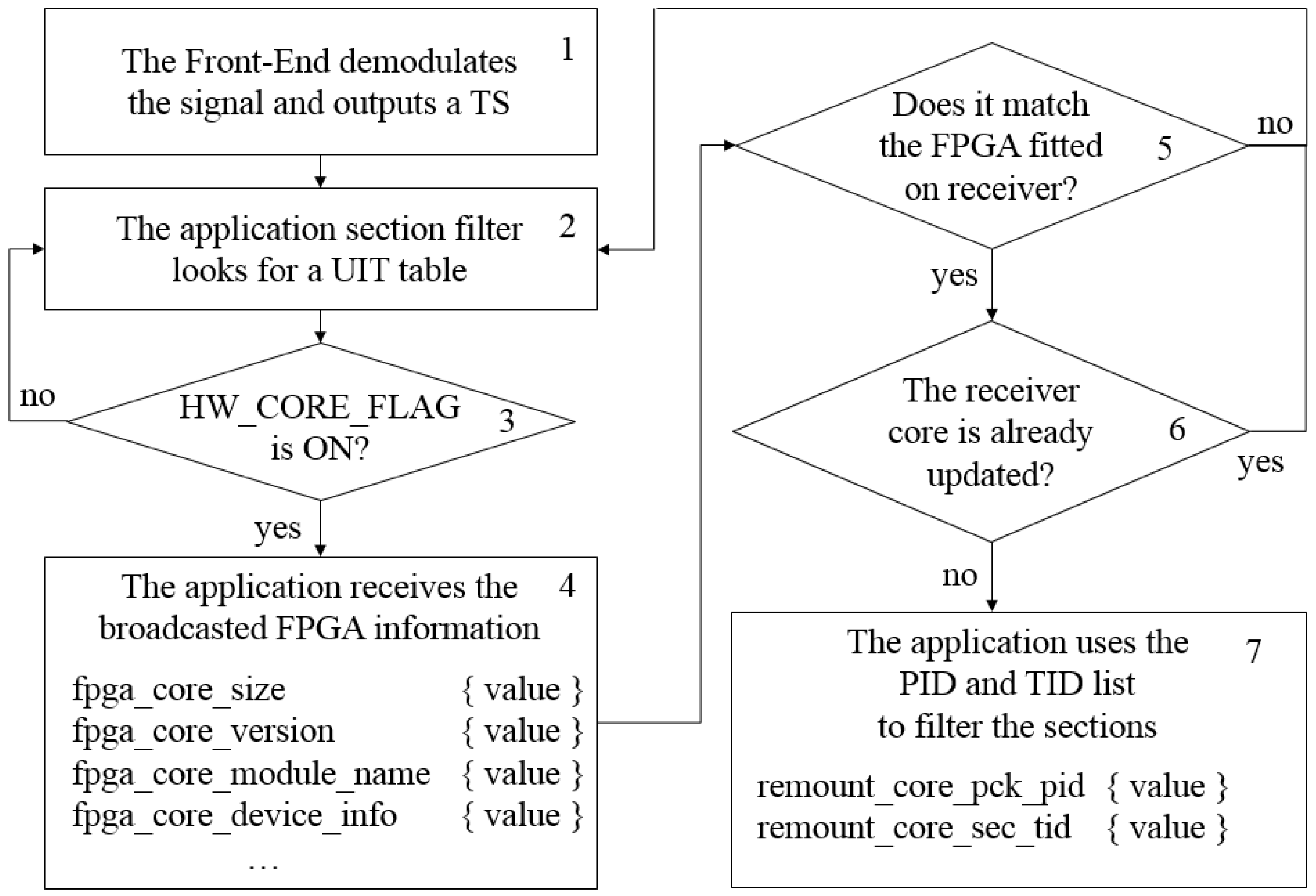
A DTV receiver’s resident system is configured to filter the transmitted content to find some hardware reconfiguration bitstream (core). It will look for a UIT and then parse it, beginning with hw_core_flag. If it is set to “0x0”, it merely ignores the current UIT; otherwise, it is set to “0x1”, where there is hardware bitstream content to be considered, and it parses the remaining UIT content (e.g., fpga_core_size, fpga_core_version, and fpga_core_module_name()) to retrieve the corresponding table fields, which describe characteristics of a given broadcast bitstream (hardware core). Finally, such values are compared with those of the local FPGA devices as shown in Figure 7. The characteristics of the local FPGA devices can be stored in a simple text file, which is made available at a receiver’s file system, as performed here.

Figure 7.
Steps to check the UIT content and find broadcast core hardware suitable for a receiver to retrieve the correct PIDs for filtering.
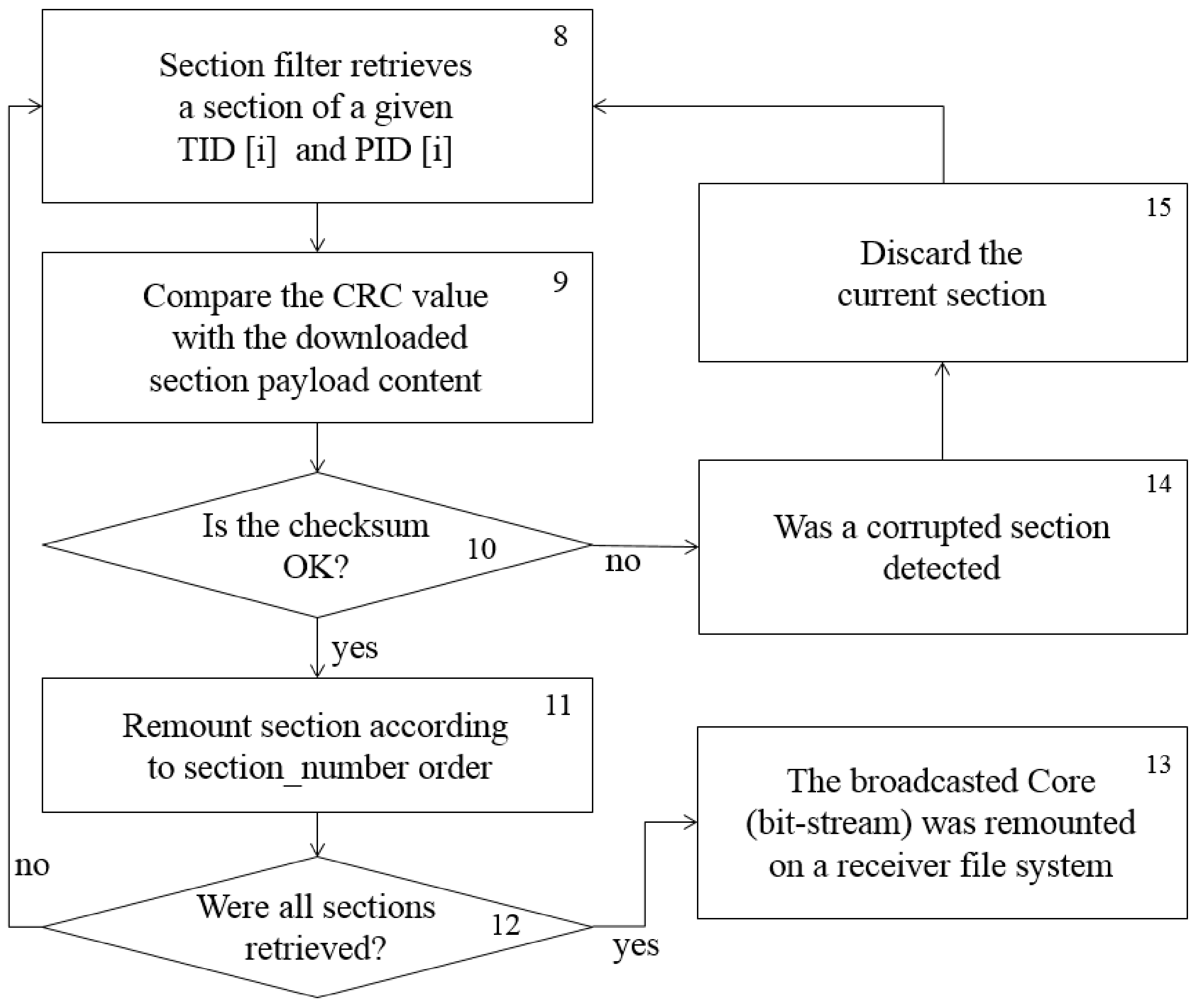
On the one hand, if some of those fields do not match a receiver’s hardware characteristics, it interrupts the reconfiguration process. Indeed, this may happen, given that the content may have been sent to another kind of receiver with different FPGA devices. On the other hand, if such content fits a receiver, it continues the filtering procedure and parses remount_core_pck_pid and remount_core_sec_tid. Those values are used as access points for extracting the transmitted reconfiguration bitstreams (for programming the section-filtering modules) directly from the private sections as depicted in Figure 8. When a private section is retrieved, its CRC is checked for validation purposes (see Section 3.1). If it is not corrupted, the receivers can store their payload according to the section order provided by section_number; otherwise, they will wait for a new section. In case of a system reset, the downloaded content is discarded, and the working memory is cleaned, being necessary to restart the bitstream remounting process.
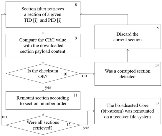
Figure 8.
Steps involved in obtaining broadcast hardware core streams include verification of each private section, downloading, and content reassembling.
A receiver keeps this iterative process until the last section is received to conclude the reassembling processes. However, this procedure’s completion depends on validating an entire private section’s payload. If a section is not validated (e.g., it is corrupted), a reconfiguration process discards that, and the search for a valid section content continues. Given that sections may be randomly retrieved, any receiving system is responsible for ensuring the correct order.
5.4. Target Device Reconfiguration
The FPGA reconfiguration is the last step of HARD. The main idea is to exercise the complete chain (i.e., from its beginning (core multiplexing) to its end (FPGA reconfiguration)). At this point, a receiver has already checked if the core characteristics fit its FPGA model (see Section 5.3) and finished system core reassembling (obtained the broadcast SVF file). Now, in this step, the remounted hardware core streams reach a receiver’s reconfigurable target device through a JTAG mode, as presented in Section 4.1.
5.5. Discussion about HARD
Figure 9 summarizes HARD, as explained in Section 5.1, Section 5.2, Section 5.3, and Section 5.4. As shown in Figure 9, HARD provides the transmission of pre-synthesized hardware cores through MPEG-2 TSs in such a way that the FPGA devices integrated into the commercial receivers are addressed. Aside from that, the same content transmission strategy already used for general data and SI (e.g., tables and sections) in digital television systems [56,57] is employed.
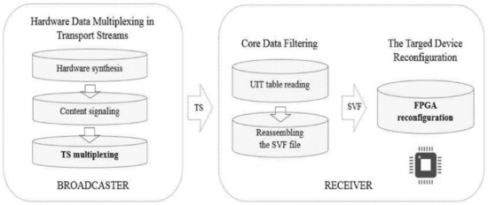
Figure 9.
All steps performed in HARD.
The presented reconfiguration system is based on JTAG communication, the SVF files retrieved from digital TV signals, a newly created SI table (UIT), and its associated descriptors (see Section 5.2). The SVF format is a standard used by almost all FPGA manufacturers and is compliant with the JTAG communication protocol. Additionally, HARD’s SI extension carries all necessary FPGA devices (e.g., manufacturer, part number, and family identification) under update, which allows complete identification of a given unit. Consequently, it is not restricted to a specific manufacturer or FPGA model, and it is also flexible enough to be adapted to other scenarios. For instance, nearly any given format can be sent in private sections, as long as the related content is regular data flow.
Regarding content reception, pre-synthesized cores will be accepted if there is a match between the transmitted information, which was filtered from UIT, and the locally available FPGA devices; otherwise, the receiving systems simply ignore the acquired content and wait for suitable data.
It is worth noticing that HARD presents some overhead related to encapsulation in private sections (i.e., the private section header and SVF file format), including JTAG commands. The total overhead is given by
where N is the total number of sections necessary to carry the hardware reconfiguration content, 16 bytes is the size of the private section headers (4096 − 4080 = 16), and 3 Kbytes is related to the SVF syntax and header file.
overhead = (N × 16 bytes + 3 Kbytes)
HARD is based on an extension of SI standards [59,60] without modifying current structures. It uses a new table (UIT) and associated descriptors inspired by AIT’s architecture. Although that may seem intricate, its implementation is transparent and can be performed without formally modifying the related standards as a proprietary framework. Apart from that, the present approach addresses its complete update chain and provides a comprehensive and complete solution, which is still more feasible and more straightforward than isolated proprietary solutions or on-site maintenance.
Another exciting research topic about this work is security. Although not its focus, given that the main goals were to prove feasibility and provide a complete and consistent framework which could be readily used and further extended, some ideas may be tackled. There is a trend toward adopting security-by-design approaches, where built-in security tools are already available within frameworks; that is, systems are designed from the ground up to be secure [61]. Another initiative is proof-carrying hardware (PCH), which may mitigate malicious code’s addition to IP modules by providing functional specifications and security properties [62,63]. An automatic proof checker validates the modules through a device code and property proof. In summary, regarding HARD, security tools can be added later to host systems and other parts of the present framework (e.g., SI) to prevent hardware trojans or attacks on embedded systems.
Finally, the present proposal deals with evolution and standard updates directly related to resource availability for future hardware modules. Complexity measurements depend on many issues, like the chosen platform and desired performance. Aside from that, the toolset choice of a standard is not necessarily coupled to the implementation complexity. For instance, regarding video coding, some authors [3] initially suggested that the software implementation cost of an HEVC decoder would not be much higher than that of an H.264/AVC one, although this is not obvious. That aside, one may notice that the number of used logic gates may be highly influenced by the parallelism supported by the HEVC standard [64]. Given that IP developers already have broad experience with previous solutions (e.g., MPEG-1, MPEG-2, MPEG-4 AVC/H.264, and HEVC), they may be able to roughly predict future needs and then advise STB manufacturers to integrate FPGA devices that, for instance, may be updated for one or two future generations.
6. Simulation Results
The Materials and Methods should be described with sufficient details to allow others to replicate and build on the published results. Please note that the publication of your manuscript implicates that you must make all materials, data, computer code, and protocols associated with the publication available to readers. Please disclose at the submission stage any restrictions on the availability of materials or information. New methods and protocols should be described in detail, while well-established methods can be briefly described and appropriately cited.
As a proof of concept (PoC), some HDL source code examples were synthesized, whose goal was to use the entire scheme. Four VHDL and Verilog examples were used, which were synthesized for a reference FPGA and then tested and validated employing an EDA tool.
The experimental set-up used in this work included a toolset necessary for validating all steps performed by HARD. To synthesize the digital circuits, Quartus II v.11.0, provided by Altera FPGA manufacturer, was used. Such a tool can generate a reprogramming file in several formats, including the chosen one, which was SVF. The advanced stream combiner (ASC) tool, provided by Rohde & Schwarz, was employed to multiplex the content in a TS. The UIT section was added during TS creation, and the SVF’s content was split and encapsulated into private sections. Modulation and broadcasting were achieved by using a VHF/UHF modulator (DekTec DTU-215, USB-2 device) with a companion player tool (StreamXpress v.3.10.2, also provided by DekTec), which transmits signals according to the Integrated Services Digital Broadcasting Terrestrial (ISDB-T) standard [65]. The receiver device used for testing and development was an NXP-STB225 IP, a hybrid DTV-STB platform provided by NXP semiconductors. The mentioned platform runs a version of the Linux operating system on a 300-MHz MIPS processor. Finally, the employed FPGA device was a Nios Stratix EP1S10F780C6 development board, which was developed by Altera and ran at 50 MHz.
The proposed validation was based on typical examples to check if the mentioned FPGA device was configured correctly, and the proposed scheme works in a DTV system. The first pre-synthesized example converted to an SVF file (see Section 3) was a simple binary-coded decimal (BCD) light-emitting diode (LED) counter (Ex01.svf). The second one was a BCD to 7-segment decoder (Ex02.svf). The third was an example that wrote a text message on a 16x2 liquid crystal display (LCD) device (Ex03.svf). Finally, the fourth and last one was a 7-segment counter (Ex04.svf).
According to the schema described in this work, each core was multiplexed into its respective TS (see Section 5.1, Section 5.2, Section 5.3, and Section 5.4). The result of this process consisted of four transport stream files carrying and signaling each respective bitstream. The TS example files were generated according to the ISDB-T standard [65], similar to what is performed in terrestrial DVB. For this process, the said MPEG2 TS generator and packet manipulator tool were employed. The bit rate used to multiplex each transport stream was 1.57 Mbps.
The first set of experiments was performed to establish the best section repetition rate used in HARD. Regarding that, eight transport streams carrying and signaling the Ex01.svf hardware core were generated. Thus, for the first example, the repetition rate used was 500 ms. Next, repetition rates of 750 ms, 1000 ms, 1250 ms, 1500 ms, 1750 ms, and 2000 ms were successively tested (see Table 8).
Table 8.
Remounting time (RMT) values obtained for the first pre-synthesized example using different repetition rates.
According to Table 8, the results using a rate of 500 ms (Ex01_500ms.ts) presented the lowest performance during the remounting process with private sections. With this specific rate, the remounting system had a greater discarding of sections than lower rates, which happens when the remounting system captures a smaller number of sections in each repetition cycle. When using 750 ms (Ex01_750ms.ts), there was an improvement in the remounting performance due to reduced discarding of sections compared with the 500-ms repetition rate. However, the rates between 1000 ms and 1500 ms presented the best average performance during the hardware core remounting procedure. It is worth noticing that the mentioned rates provided similar remounting times but with a clear upward trend regarding this merit figure. The other experiments were based on a private section rate of 1000 ms, with a UIT rate set to 1000 ms. The mentioned USB 2.0-based multi-standard modulator was used to perform TS broadcasting.
Some results were generated for validating the correct operation of the entire scheme. The metrics evaluated here were the remounting time (RMT) (i.e., the time for downloading reconfiguration data) and the reconfiguration time (RCT), which is the period employed to parse the related SVF file and to reconfigure a target FPGA, with the latter occurring if an RMT process has occurred, as well as the sum of the checksum verification time necessary to check all sections and the download time for all sections (remounting). RCT is the total time needed to reconfigure an FPGA device using the implemented JTAG host/target mode. Table 9 shows the obtained results when the broadcast and reception tests were performed using this reconfiguration scheme.
Table 9.
Remounting and reconfiguration time values obtained for all the employed pre-synthesized examples using a repetition rate of 1000 ms.
The HWname table column represents the pre-synthesized core file name. Column CRsize shows the pre-synthesized core size, followed by TSname, which is the generated TS file name. Finally, the RMT and RCT fields show the obtained average remounting time and average reconfiguration time values, respectively.
The performed experiments showed that pre-synthesized cores could be signaled, multiplexed, and broadcast with DTV content. The achieved RMTs in each test were satisfactory, considering that the proposed scheme’s task was performed in concurrency with other DTV tasks (e.g., application retrieval, table filtering, and electronic program guide construction). The RCTs were also satisfactory, considering that the employed reference receiver presented low processing power. Indeed, the developed SVF parser took most of the elapsed time. The reconfiguration JTAG mode is generic and ideal for this PoC, but that can be improved if FPGA devices are integrated into the receiver boards, which would be the case in a complete commercial solution.
The RMT value associated with Ex02.svf was larger than what was obtained even with Ex04.svf, which was due to the platform conditions and scheduling at that time (other processes were running). Although all the test files presented nearly the same size, the resulting RMT depended on factors such as the start point related to the private sections, signal strength, and corrupted private sections. Regarding final users, those periods were not perceived, given that the associated tasks were performed in parallel with other receiver tasks. However, if a reconfigured FPGA device was being used (e.g., for media decoding), momentary service interruption may have been noticed.
The hardware reconfiguration scheme presented here is an innovative approach compared with the literature on reconfigurable architectures. The main idea of HARD relies on a delivery methodology for pre-synthesized hardware cores.
Recent studies (as seen in Section 2) used pre-synthesized cores for runtime reconfiguration and presented similarities with HARD. The main difference is that the former need to maintain several previously stored cores. Then, a resident system must decide when to use each one. HARD, in turn, can broadcast cores to a considerable number of devices, which are then automatically reconfigured. That aside, it could send the pre-synthesized cores of several manufacturers, and each device would then be responsible for accepting or rejecting specific content.
Another feature is that a broadcaster can send hardware update data cyclically, allowing all devices in range to perform hardware reconfiguration. Thus, in DTV networks, where receivers are based on replacing hardware modules, new technology advances and enhancements could be immediately incorporated, leading to a flexible DTV environment.
7. Conclusions
This work presents a new approach for hardware reconfiguration, which is intended to be used in DTV environments. HARD allows receivers to be automatically reconfigured, providing a strategy to create new device structures. Additionally, receiver architectures could be focused on hardware upgrades in numerous ways.
The results obtained with the present experiments show that commercial systems can reconfigure distinct core modules in a DTV system. Additionally, the proposed reconfiguration scheme can work in parallel with other DTV tasks. Indeed, the obtained remounting times are satisfactory, considering embedded systems with low processing power, and the reconfiguration ones can be improved if FPGAs are integrated into the receiver boards.
Additionally, the chosen examples are simple enough to allow fast implementation and easy multiplexing, and they are complex enough in such a way that the complete hardware update chain is used to reveal its complexity and show its validity.
Critical tasks generally performed by an ASIC device, such as H.264 video decoding and cryptography tasks, could be designed for FPGA devices based on the present scheme. It would enable the incorporation of technological advances, such as new video compression schemes, which would create a flexible DTV network. Furthermore, other devices that use transport streams could also use HARD to design intelligent architectures and flexible, low-cost devices.
It is worth noticing that the overhead presented by the proposed methodology is mostly affected by the pre-synthesized file format. Universal formats, such as SVF, include more information in their file headers, which increases the final file sizes. Consequently, many private sections would be needed, and the remounting process at the receivers would be slower. It is necessary to parse reconfiguration files and extract the SVF syntax, which is performed before the reconfiguration process and increases the system overhead. The associated file overhead could be reduced by using proprietary or dedicated reconfiguration schemes; however, the universal behavior of such a scheme would be lost.
Finally, our methodology does not tackle security, as we expect that trusted elements (i.e., broadcasters) send reconfiguration data. Indeed, when dealing with middlewares, their authorization and general data specifically seem reliable and guide the resulting reception procedure. In addition, tampering with or attacking DTV signals (transport streams) is not a usual practice.
Author Contributions
Conceptualization, R.R.d.O. and V.F.d.L.J.; methodology, R.R.d.O. and V.F.d.L.J.; software, R.R.d.O. and F.A.S.G.; validation, L.C.C., E.B.d.L.F. and V.F.d.L.J.; investigation, R.R.d.O. and V.F.d.L.J.; resources, V.F.d.L.J.; data curation, M.M.d.L. and F.A.S.G.; writing—original draft preparation, R.R.d.O. and V.F.d.L.J.; writing—review and editing, F.A.S.G., M.M.d.L., E.B.d.L.F. and L.C.C.; visualization, M.M.d.L.; supervision, V.F.d.L.J.; project administration, V.F.d.L.J.; funding acquisition, V.F.d.L.J. All authors have read and agreed to the published version of the manuscript.
Funding
This research was funded by CNPq, CAPES, FAPEAM, and Samsung.
Institutional Review Board Statement
Not applicable.
Informed Consent Statement
Not applicable.
Data Availability Statement
Data is stored on the PPGEE database and may be made available upon request.
Acknowledgments
This research, in accordance with Article 48 of Decree n° 6.008/2006, was funded by Samsung Electronics of Amazonia Ltd.a under the terms of Federal Law n° 8.387/1991 and through agreement n° 004, signed with CETELI/UFAM. We also would like to acknowledge the financial support from CAPES, CNPq, and FAPEAM.
Conflicts of Interest
The authors declare no conflict of interest.
References
- Yoshida, D.; Takahashi, M.; Mizosoe, H.; Nakamura, T.; Yatabe, Y. Highly efficient H.264/AVC codec technology for high definition consumer applications. In Proceedings of the IEEE International Conference on Consumer Electronics, Las Vegas, NV, USA, 9–13 January 2008; pp. 1–2. [Google Scholar]
- Sullivan, G.J.; Ohm, J.R.; Han, W.-J.; Wiegand, T. Overview of the high efficiency video coding (HEVC) standard. Trans. Circuits Syst. Video Technol. 2012, 22, 1649–1668. [Google Scholar] [CrossRef]
- Bossen, F.; Bross, B.; Shring, K.; Flynn, D. HEVC complexity and implementation analysis. IEEE Trans. Circuits Syst. Video Technol. 2012, 22, 1685–1696. [Google Scholar] [CrossRef] [Green Version]
- Flynn, D.; Marpe, D.; Naccari, M.; Nguyen, T.; Rosewarne, C.; Sharman, K.; Sole, J.; Xu, J. Overview of the Range Extensions for the HEVC Standard: Tools, Profiles, and Performance. IEEE Trans. Circuits Syst. Video Technol. 2015, 26, 4–19. [Google Scholar] [CrossRef]
- Pescador, F.; Chavarrias, M.; Garrido, M.J.; Juarez, E.; Sanz, C. Complexity analysis of an HEVC decoder based on a digital signal processor. IEEE Trans. Consum. Electron. 2013, 59, 391–399. [Google Scholar] [CrossRef]
- Ayadi, L.A.; Damak, T.; Loukil, H.; Ayed, M.A.B.; Masmoudi, N. HEVC Decoder Analysis on ARM Processor. In Proceedings of the 2018 15th International Multi-Conference on Systems, Signals & Devices (SSD), Yasmine Hammamet, Tunisia, 19–22 March 2018; pp. 842–845. [Google Scholar]
- IEEE Standard. IEEE Approved Draft Standard for VHDL Language Reference Manual; IEEE P1076/D13: New York, USA, 2019; pp. 1–796. Available online: https://ieeexplore.ieee.org/servlet/opac?punumber=8782173 (accessed on 3 September 2021).
- IEEE Standard. IEEE Draft Standard for SystemVerilog—Unified Hardware Design, Specification, and Verification Language. In Proceedings of the IEEE P1800/D3, April 2017 (Revision of IEEE Std 1800-2012), New York, NY, USA, 1 January 2017; pp. 1–1316. Available online: https://ieeexplore.ieee.org/servlet/opac?punumber=7921683 (accessed on 3 September 2021).
- Ahmed, S.Z.; Sassatelli, G.; Torres, L.; Rougé, L. Survey of new trends in industry for programmable hardware: FPGAs, MPPAs, MPSoCs, structured ASICs, eFPGAs and new wave of innovation in FPGAs. In Proceedings of the International Conference on Field Programmable Logic and Applications, Milano, Italy, 31 August–2 September 2010; pp. 291–297. [Google Scholar]
- Reddy, B.K.; Sabbavarapu, S.; Acharyya, A. A new VLSI IC design automation methodology with reduced NRE costs and time-to-market using the NPN class Representation and functional symmetry. In Proceedings of the IEEE International Symposium on Circuits and Systems, Melbourne, Australia, 1–5 June 2014; pp. 177–180. [Google Scholar]
- Leong, P.H.W. Recent trends in FPGA architectures and applications. In Proceedings of the IEEE International Symposium on Electronic Design, Test and Applications, Hong Kong, SAR, China, 23–25 January 2008; pp. 137–141. [Google Scholar]
- Yu, S.; Chen, P. Emerging Memory Technologies: Recent Trends and Prospects. IEEE Solid-State Circuits Mag. 2016, 8, 43–56. [Google Scholar] [CrossRef]
- Salman, A.H.; Adiono, T.; Cahyadi, W.A.; Kurniawan, Y. SOC design and FPGA implementation of Digital TV receiver. In Proceedings of the International Conference on Telecommunication Systems, Services, and Applications, Denpasar-Bali, Indonesia, 30–31 October 2012; pp. 125–129. [Google Scholar]
- ABNT Standard. Digital Terrestrial Television, Video Coding, Audio Coding and Multiplexing Part 3: Signal Multiplexing Systems. ABNT NBR 15602-3, November 2007. Available online: https://www.dibeg.org/techp/aribstd/harmonization/(2018_04_11)4_Multiplexing_ABNT_ARIB_SBTVD_JD.pdf (accessed on 3 September 2021).
- Lin, C.-T.; Horng, S.-J.; Huang, Y.-L. Hardware resource manager for reconfiguration system. In Proceedings of the International Symposium on Biometrics and Security Technologies, Taipei, Taiwan, 26–29 March 2012; pp. 59–65. [Google Scholar]
- Li, A.; Hailes, P.; Maunder, R.G.; Al-Hashimi, B.M.; Hanzo, L. 1.5 Gbit/s FPGA Implementation of a Fully-Parallel Turbo Decoder Designed for Mission-Critical Machine-Type Communication Applications. IEEE Access 2016, 4, 5452–5473. [Google Scholar] [CrossRef]
- Ibraheem, M.S.; Hachicha, K.; Romain, O. Fast and Parallel AAC Decoder Architecture for a Digital Radio Mondiale 30 Receiver. IEEE Access 2017, 5, 14638–14646. [Google Scholar] [CrossRef]
- Wang, Q.; Li, Q.; Chen, S.; Zhang, T.; Hou, C. An optimized hardware architecture for intra prediction in H.264 decoder. In Proceedings of the 2013 IEEE 10th International Conference on ASIC, Shenzhen, China, 28–31 October 2013; pp. 1–4. [Google Scholar]
- Kammoun, M.; Atitallah, A.B.; Masmoudi, N. An optimized hardware architecture for intra prediction for HEVC. In Proceedings of the International Image Processing, Applications, and Systems Conference, Sfax, Tunisia, 5–7 November 2014; pp. 1–5. [Google Scholar]
- Hailes, P.; Xu, L.; Maunder, R.G.; Al-Hashimi, B.M.; Hanzo, L. A Flexible FPGA-Based Quasi-Cyclic LDPC Decoder. IEEE Access 2017, 5, 20965–20984. [Google Scholar] [CrossRef]
- Chen, D.; Chen, P.; Fang, Y. Low-Complexity High-Performance Low-Density Parity-Check Encoder Design for China Digital Radio Standard. IEEE Access 2017, 5, 20880–20886. [Google Scholar] [CrossRef]
- Maheshwarappa, M.R.; Bowyer, M.D.J.; Bridges, C.P. Improvements in CPU & FPGA Performance for Small Satellite SDR Applications. IEEE Trans. Aerosp. Electron. Syst. 2017, 53, 310–322. [Google Scholar]
- Zheng, Y.; Zhao, S.; Liu, Y.; Li, Y.; Tan, Q.; Xin, N. Weighted Algebraic Connectivity Maximization for Optical Satellite Networks. IEEE Access 2017, 5, 6885–6893. [Google Scholar] [CrossRef]
- Ferdian, R.; Hou, Y.; Okada, M. A Low-Complexity Hardware Implementation of Compressed Sensing-Based Channel Estimation for ISDB-T System. IEEE Trans. Broadcasting 2017, 63, 92–102. [Google Scholar] [CrossRef]
- Shawahna, A.; Sait, S.M.; El-Maleh, A. FPGA-Based Accelerators of Deep Learning Networks for Learning and Classification: A Review. IEEE Access 2019, 7, 7823–7859. [Google Scholar] [CrossRef]
- Lallet, J.; Enrici, A.; Saffar, A. FPGA-Based System for the Acceleration of Cloud Microservices. In Proceedings of the 2018 IEEE International Symposium on Broadband Multimedia Systems and Broadcasting (BMSB), Valencia, Spain, 6–8 June 2018; pp. 1–5. [Google Scholar]
- Pinneterre, S.; Chiotakis, S.; Paolino, M.; Raho, D. vFPGAmanager: A Virtualization Framework for Orchestrated FPGA Accelerator Sharing in 5G Cloud Environments. In Proceedings of the 2018 IEEE International Symposium on Broadband Multimedia Systems and Broadcasting (BMSB), Valencia, Spain, 6–8 June 2018; pp. 1–5. [Google Scholar]
- Khalgui, M.; Mosbahi, O.; Li, Z. On Reconfiguration Theory of Discrete-Event Systems: From Initial Specification Until Final Deployment. IEEE Access 2019, 7, 18219–18233. [Google Scholar] [CrossRef]
- Ghribi, I.; Abdallah, R.B.; Khalgui, M.; Li, Z.; Alnowibet, K.; Platzner, M. R-Codesign: Codesign Methodology for Real-Time Reconfigurable Embedded Systems Under Energy Constraints. IEEE Access 2018, 6, 14078–14092. [Google Scholar] [CrossRef]
- Wiśniewski, R. Dynamic Partial Reconfiguration of Concurrent Control Systems Specified by Petri Nets and Implemented in Xilinx FPGA Devices. IEEE Access 2018, 6, 32376–32391. [Google Scholar] [CrossRef]
- Pham, T.H.; Fahmy, S.A.; McLoughlin, I.V. An End-to-End Multi-Standard OFDM Transceiver Architecture Using FPGA Partial Reconfiguration. IEEE Access 2017, 5, 21002–21015. [Google Scholar] [CrossRef]
- Gharsellaoui, H.; Khalgui, M. Dynamic Reconfiguration of Intelligence for High Behaviour Adaptability of Autonomous Distributed Discrete-Event Systems. IEEE Access 2019, 7, 35487–35498. [Google Scholar] [CrossRef]
- Guerrieri, A.; Kashani-Akhavan, S.; Asiatici, M.; Ienne, P. Snap-On User-Space Manager for Dynamically Reconfigurable System-on-Chips. IEEE Access 2019, 7, 103938–103947. [Google Scholar] [CrossRef]
- Eachanobe, J.; del Campo, I.; Finker, R.; Basterretxea, K. Dynamic Partial Reconfiguration in embedded systems for intelligent environments. In Proceedings of the IEEE International Conference on Intelligent Environments, Guanajuato, Mexico, 26–29 June 2012; pp. 26–29. [Google Scholar]
- Sengupta, A.; Rathor, M. Security of Functionally Obfuscated DSP Core Against Removal Attack Using SHA-512 Based Key Encryption Hardware. IEEE Access 2019, 7, 4598–4610. [Google Scholar] [CrossRef]
- Rodríguez, A.; Santos, L.; Sarmiento, R.; Torre, E.D.L. Scalable Hardware-Based On-Board Processing for Run-Time Adaptive Lossless Hyperspectral Compression. IEEE Access 2019, 7, 10644–10652. [Google Scholar] [CrossRef]
- Housseyni, W.; Mosbahi, O.; Khalgui, M.; Li, Z.; Yin, L.; Chetto, M. Multiagent Architecture for Distributed Adaptive Scheduling of Reconfigurable Real-Time Tasks with Energy Harvesting Constraints. IEEE Access 2018, 6, 2068–2084. [Google Scholar] [CrossRef]
- Hu, S.; Haung, J. Exploring Adaptive Cache for Reconfigurable VLIW Processor. IEEE Access 2019, 7, 72634–72646. [Google Scholar] [CrossRef]
- Hillenbrand, D.; Brugger, C.; Tao, J.; Yang, S.; Balzer, M. RIVER: Reconfigurable pre-synthesized-streaming architecture for signal processing on FPGAs. In Proceedings of the IEEE Parallel and Distributed Processing Symposium Workshops & PhD Forum, Shanghai, China, 21–25 May 2012; pp. 397–400. [Google Scholar]
- Serres, O.; Narayana, V.K.; El-Ghazawi, T. An architecture for reconfigurable multicore explorations. In Proceedings of the International Conference on Reconfigurable Computing and FPGAs, Cancun, Mexico, 30 November–2 December 2011; pp. 105–110. [Google Scholar]
- Wang, Y.; Zhou, X.; Wang, L.; Yan, J.; Luk, W.; Peng, C.; Tong, J. SPREAD: A streaming-based partially reconfigurable architecture and programming model. IEEE Trans. Very Large Scale Integr. (VLSI) Syst. 2013, 21, 2179–2192. [Google Scholar] [CrossRef] [Green Version]
- ISO/IEC International Standard. Information Technology–Generic Coding of Moving Pictures and Associated Audio Information: Systems. ISO/IEC 13818-1. December 2000. Available online: https://www.iso.org/standard/75928.html (accessed on 3 September 2021).
- ABNT Standard. Digital Terrestrial Television, Data Coding, and Transmission Specification for Digital Broadcasting Part 3: Data Transmission Specification. ABNT NBR 15606-3. March 2012. Available online: https://www.abntcatalogo.com.br/default.aspx (accessed on 3 September 2021).
- Park, M.S.; Lee, Y.J.; Choi, J.H.; Choi, J.S. The design and implementation of data server for data broadcast service. In Proceedings of the International Conference on Electronics, Circuits and Systems, Sharjah, United Arab Emirates, 14–17 December 2003; Volume 3, pp. 1176–1179. [Google Scholar] [CrossRef]
- Tozer, E.P.J. Broadcast Engineer’s Reference Book; Focal Press: Burlington, VT, USA, 2004; pp. 352–355. [Google Scholar]
- Fischer, W. Digital Video and Audio Broadcasting Technology: A Practical Engineering Guide; Springer: Heidelberg, Germany, 2010; pp. 457–465. [Google Scholar]
- Castagnoly, G.; Brauer, S.; Herrmann, M. Optimization of cyclic redundancy-check codes with 24 and 32 parity bits. IEEE Trans. Commun. 1993, 41, 883–892. [Google Scholar] [CrossRef]
- Reimers, U. DVB: The Family of International Standards for Digital Video Broadcasting, 2nd ed.; Springer: Berlin, Germany, 2005; pp. 287–288. [Google Scholar]
- Digital Video Broadcasting. Specification for Data Broadcasting. ETSI EN301 192-V1.5.1. November 2009. Available online: https://www.etsi.org/deliver/etsi_en/301100_301199/301192/01.05.01_60/en_301192v010501p.pdf (accessed on 3 September 2021).
- Digital Video Broadcasting. Implementation Guidelines for Data Broadcasting. ETSI TR 101 202-V1.2.1. January 2003. Available online: https://www.etsi.org/deliver/etsi_tr/101200_101299/101202/01.02.01_60/tr_101202v010201p.pdf (accessed on 3 September 2021).
- Crinon, R.J. The DSM-CC object carousel for broadcast data services. In Proceedings of the IEEE International Conference on Consumer Electronics, Rosemont, Vt, USA, 11–13 June 1997; pp. 246–247. [Google Scholar]
- Lin, F.; Sun, J. An Interactive Service Platform Solution Based on Enhanced Data Carousel Scheme. IEEE Trans. Consum. Electron. 2007, 53, 675–682. [Google Scholar] [CrossRef]
- ABNT Standard. Digital Terrestrial Television—Receivers; ABNT NBR 15604; ABNT Standard: Sao Paulo, Brazil, November 2007. [Google Scholar]
- Stavinov, E. 100 Power Tips for FPGA Designers; CreateSpace Independent Publishing Platform: Charleston, SC, USA, 2011; pp. 171–200. [Google Scholar]
- IEEE Standard. IEEE Standard for Test Access Port and Boundary-Scan Architecture. IEEE Std. 1149.1. 2013. Available online: https://ieeexplore.ieee.org/servlet/opac?punumber=6759736 (accessed on 3 September 2021).
- M Strubel. Implementing JTAG Debugging Solutions for Custom Hardware; Embedded World: Nuremberg, Germany, 2012; pp. 1–17. [Google Scholar]
- Dominic, R. Design and Implementation of an On-Chip Debug Solution for Embedded Target Systems Based on the ARM7 and ARM9 Family. Ph.D. Thesis, University of Applied Sciences Augsburg, Augsburg, Germany, 2005. [Google Scholar]
- Parker, K.P. The Boundary-Scan Handbook, 3rd ed.; Kluwer Academic Publishers: Boston, MA, USA, 2003; pp. 10–60. [Google Scholar]
- Digital Video Broadcasting. Specification for Service Information (SI) in DVB systems. ETSI EN 300 468-V1.14.1. May 2014. Available online: https://www.etsi.org/deliver/etsi_en/300400_300499/300468/01.14.01_60/en_300468v011401p.pdf (accessed on 3 September 2021).
- ARIB Standard. Service Information for Digital Broadcasting System. ARIB STD-B10-V4.6-E2. June 2008. Available online: https://www.arib.or.jp/english/html/overview/doc/6-STD-B10v4_6-E2.pdf (accessed on 3 September 2021).
- Souren, J. Security by Design: Hardware-Based Security in Windows 8. Comput. Fraud. Secur. 2013, 5, 18–20. [Google Scholar] [CrossRef]
- Love, E.; Jin, Y.; Makris, Y. Proof-carrying hardware intellectual property: A pathway to trusted module acquisition. IEEE Trans. Inf. Forensics Secur. 2011, 7, 25–40. [Google Scholar] [CrossRef]
- Jin, Y.; Makris, Y. A proof-carrying based framework for trusted microprocessor IP. In Proceedings of the IEEE/ACM International Conference on Computer-Aided Design, San Jose, CA, USA, 18–21 November 2013; pp. 824–829. [Google Scholar]
- ISO/IEC International Standard. Information Technology—High Efficiency Coding and Media Delivery in Heterogeneous Environment—Part 2: High Efficiency Video Coding. ISO/IEC 23008-2. May 2015. Available online: https://www.iso.org/standard/67660.html (accessed on 3 September 2021).
- ARIB Standard. Transmission System for Digital Terrestrial Television Broadcasting. ARIB STD-B31. November 2005. Available online: https://dokumen.tips/documents/arib-std-b31.html (accessed on 3 September 2021).


Publisher’s Note: MDPI stays neutral with regard to jurisdictional claims in published maps and institutional affiliations. |
© 2021 by the authors. Licensee MDPI, Basel, Switzerland. This article is an open access article distributed under the terms and conditions of the Creative Commons Attribution (CC BY) license (https://creativecommons.org/licenses/by/4.0/).