Abstract
As a promising application for autonomous driving, vehicle platooning aims at increasing traffic throughput, improving road safety, and reducing air pollution and fuel consumption. However, frequent traffic perturbations will bring more fuel consumption because vehicles driving in a platoon require more control to ensure safe driving, especially in high-density scenes. In this paper, considering the traffic perturbations and high-density scenes, we integrate communication and control systems to reduce the fuel consumption of a platoon. By obtaining the velocities of multiple vehicles ahead through a long-term evolution-vehicle (LTE-V) network, we propose a modified distributed model predictive control (DMPC) method to smooth traffic perturbations and handle the constraints of vehicle state and control. In addition, considering a limited number of uplink channels that can be reused in the platoon and the uncertainty of wireless channels, a radio resource allocation optimization problem in the LTE-V network is modeled. This problem is solved in two steps including maximum vehicle-to-vehicle (V2V) broadcast distance and minimum weight matching. This resource allocation scheme increases the platoon-based V2V broadcast distance while ensuring the ergodic capacity requirement of the cellular user (CUE) uplink communication and the reliability of platoon-based V2V communication. Simulation results show that the proposed method improves fuel efficiency compared to the existing schemes.
1. Introduction
In recent years, rapidly-growing vehicular traffic has led to the heavy urban traffic, unbearable road resources, frequent traffic accidents, and poor passenger experience. One useful solution to address such problems is vehicle platooning. The objective of vehicle platooning is to maintain the desired distance from the preceding vehicle and reduce the velocity error between the successive vehicles [1]. The platoon-based driving pattern has many advantages such as a smoother traffic flow, higher traffic safety, and more efficient fuel savings. Vehicle platooning is accomplished by the utilization of an automated controller that relies on the kinetic status information (e.g., acceleration, velocity, position) regarding other vehicles. Earlier studies suggest that the kinetic status of the vehicle is obtained by on-board sensors, such as radars or cameras. Recent advances in wireless vehicle-to-vehicle (V2V) communications make it possible for a vehicle to exchange information with one or more preceding vehicles. In such a case, platoon members (PMs) can drive more closely, accurately, and safely, with braking and accelerating done cooperatively and synchronously.
To enable V2V communication in the vehicle platoon, two families of radio technologies, i.e., IEEE 802.11p and long-term evolution-vehicle (LTE-V), can be fully utilized [2]. Due to the Carrier Sense Multiple Access with Collision Avoidance (CSMA/CA) mechanism, the performance of IEEE 802.11p degrades significantly in congested scenarios. In 3GPP Release 14, the LTE-V standard is defined for vehicular communications based on the cellular infrastructure [3]. Compared to IEEE 802.11p, LTE-V modifies the physical layer of long-term evolution (LTE) and attempts to provide improvements in short distance direct communication, low latency, and high reliability [4]. Many studies have been proposed to utilize LTE-V technology for vehicle platooning in recent years [5,6,7,8,9,10]. In [5], the authors addressed the technical feasibility of centralized longitudinal control of vehicle platooning through LTE communication. Ref. [6] studied the application of LTE device-to-device (D2D) technology in platoon data transmission. It leveraged the periodicity of the message to coordinate radio resources and provided spatial reuse of resources within and among platoons. For the multi-platooning scenario, based on LTE communication technology, a power control technology and a subchannel allocation scheme were proposed for V2V communications [7]. Due to the short inter-vehicle distance in the platoon, it utilized low transmission power to provide spatial reuse of radio resources within and among platoons. For platoon application, while satisfying the constraints of reliability of the communication link, ref. [8] proposed an algorithm to maximize the number of reused D2D links. Ref. [9] proposed an analytical model of V2V communication for platoon applications. It explored the relationship between the mean number of transmission attempts and the probability of success of sending cooperative awareness messages (CAMs). Ref. [10] proposed a group scheduling mechanism to address radio resources and mobility management of platoon in a multi-cell system. Since vehicle platooning is one of the key safety use-cases for the future evolution of LTE-V [11], in this paper, we will further promote our research work on LTE-V for platoon applications.
Control and communication are the key technologies for platoon application. Therefore, in addition to efficient platoon communication technology, platoon control technology also needs to be considered. In a platoon, by sensing information from surrounding vehicles, each PM controls its speed or acceleration to maintain the desired inter-vehicle spacing. Since the unreliability of wireless channels could cause variation in communication topology among PMs, distributed platoon controllers are commonly used to solve this problem. There are several effective platoon distributed controllers such as linear controllers [12], optimal controllers [13], and sliding mode controllers [14]. A common limitation of these controllers is the difficulty of explicitly handling state and control constraints. To overcome the limitation, the distributed model predictive control (DMPC) method is introduced into the platoon system [15]. In the DMPC method, the optimization control problem with a finite prediction horizon is modeled and solved by each distributed controller. Then, the optimal prediction sequence is exchanged by V2V communication. Finally, the first term of the optimal prediction sequence is selected as the input to each distributed controller [16]. In the DMPC method, each distributed controller solves an optimal control problem within a finite horizon and exchanges optimization results through V2V communication. Then, the first term in each optimized sequence is applied to the corresponding distributed controller [16]. Recently, several DMPC methods have been applied for vehicle platooning. In [17], a DMPC method for heterogeneous vehicle platooning with nonlinear dynamics and unidirectional communication topologies was proposed. This method does not require all PMs to know the position and speed information of the platoon leader. In [18], aiming at a large-scale heterogeneous nonlinear vehicle platoon, a DMPC strategy was proposed to guarantee its longitudinal stability and string stability. Ref. [19] proposed a DMPC method for vehicle platooning under dynamic communication topologies. In [20], an extended DMPC approach was proposed to handle steady-state error arising from communication delays, communication dropout, and communication topology switching. The above-mentioned DMPC methods of the platoon system aimed to achieve platoon state convergence. Another type of DMPC method optimized fuel efficiency of the platoon system. To coordinate the vehicles in the platoon safely and fuel-efficiently, ref. [21] proposed a double-layer control structure for heavy-duty vehicle platooning. A multi-objective optimization controller and a control strategy considering safety were proposed in [22], which considered several factors, such as vehicle safety, passenger comfort, platoon control, and fuel efficiency. Moreover, to further improve fuel efficiency, refs. [23,24,25,26,27] considered more realistic platoon environment and vehicle dynamics.
The effective integration of platoon communication technology and control technology will improve the overall performance of platoon driving. However, the aforementioned studies ignored the interdependent performance of communication and control systems in a platoon. To date, there has been some excellent research work on the combination of the platoon control and V2V communication [28,29,30,31]. In this paper, considering the interdependence of communication and control systems, we will study fuel-efficient driving of vehicle platoon under frequent traffic perturbations. Without traffic perturbations, one way to improve fuel efficiency is to use geolocation information for vehicle optimal speed planning [32,33]. However, since the vehicle needs to respond to the speed change of the preceding vehicle, this scheme could be inapplicable in a real traffic environment. Although platoon driving can smooth traffic flow and improve fuel efficiency, it may introduce more fuel consumption to maintain platoon state convergence under frequent traffic disturbances. With frequent traffic perturbations, one way to improve fuel economy is to use V2V communication to monitor the movement of multiple vehicles ahead [34,35]. Therefore, we propose a modified DMPC method that integrates control and communication technologies. It can improve fuel efficiency while ensuring platoon state convergence. In such a context, this paper intends to provide the following main contributions:
- 1.
- To smoothly respond to traffic perturbations and explicitly handle the vehicle state and control constraints, we propose a modified DMPC method. Through joint optimization of local vehicle fuel economy and velocity error characteristics between local vehicle and multiple preceding vehicles, adaptive driving/braking torque is obtained to smoothly respond to traffic perturbations while improving fuel efficiency. In addition, a safety mechanism is designed to maintain a safe distance gap with the preceding vehicle.
- 2.
- In the LTE-V network, LTE-V mode 3 is assumed, and the underlay mode of V2V communication is adopted. Since the velocities of multiple vehicles could help the vehicle to respond to traffic perturbations smoothly and improve fuel efficiency, we model a radio resource allocation optimization problem to improve CAMs dissemination. Further, this problem is solved in two steps, including maximum V2V broadcast distance and minimum weight matching. The resource allocation scheme increases the platoon-based V2V broadcast distance while ensuring the ergodic capacity (the long-term average capacity of a time-varying channel) requirement of the cellular user (CUE) uplink communication and the reliability of platoon-based V2V communication. In the case of a limited number of uplink channels that can be reused in the platoon, this solution still maintains the state convergence and fuel efficiency of the platoon.
- 3.
- We investigate the platoon performance of the proposed modified DMPC method in different numbers of reusable uplink channels. Simulation results show that the platoon can maintain state convergence while ensuring the ergodic capacity requirement of CUE uplink communication. Furthermore, in comparison with other DMPC platoon control technologies, our proposed design has better fuel efficiency.
The rest of the paper is organized as follows. The system model is introduced in Section 2. A modified DMPC method is proposed in Section 3. A radio resource allocation scheme for platoon system is proposed in Section 4. The simulation results are shown in Section 5. Finally, the conclusions are drawn in Section 6.
Notation: Throughout this paper, and stand for the set of real numbers and nonnegative integers, respectively. indicates the set of real matrices. The set of symmetric matrices of order n is denoted by . The positive semidefinite matrix (positive definite) is labeled as . The transpose of vector or matrix is denoted by the symbol . Given a set , is the cardinality of set , and means set minus set element 0. The weighted Euclidean norm is denoted by , where x is a vector and Q is a matrix.
2. System Model
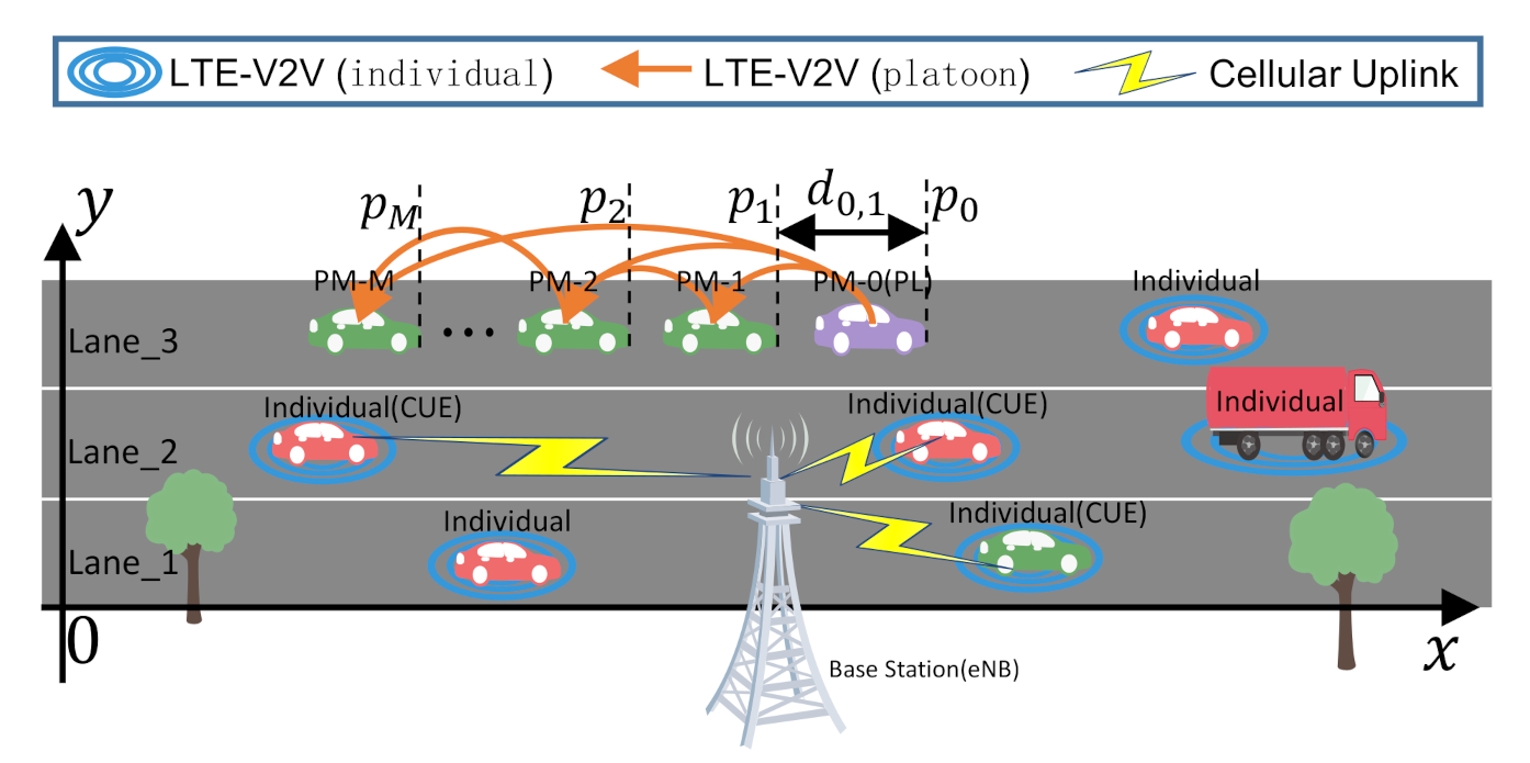
In this section, the vehicle dynamics, platoon control, fuel consumption, and communication model are described. Consider a homogeneous platoon of vehicles running on a horizontal road, as illustrated in Figure 1. Individual vehicles are randomly distributed on the lanes. Some passengers in these individual vehicles will likely request high-capacity uplink communications, which are denoted as CUEs. The PM set is labeled as , where the platoon leader is marked as 0 and the others are followers. Each PM uses an on-board global positioning system, a wireless transceiver, and other on-board sensors to obtain its vehicle state (e.g., velocity, position) and motion information of multiple vehicles ahead. The platoon-based V2V communication topology is assumed to be unidirectional, i.e., from the platoon leader to the last PM. Based on the motion information of multiple vehicles ahead, the vehicle controller can regulate its driving/braking torque for platoon driving.

Figure 1.
Platoon and individual vehicles driving scenarios.
2.1. Vehicle Dynamics
In this paper, only vehicle longitudinal control is considered. The discrete-time dynamic model of any PM i can be described as follows:
where , , and denote the position, velocity, driving/braking torque and external resistance of PM i at the time t, respectively; is the discrete time interval; is the vehicle mass; is the lumped aerodynamic drag coefficient; is the tire radius; is the mechanical efficiency of the driveline; g is the gravity constant; and is the rolling resistance coefficient. We assume that PMs are homogeneous (i.e., all vehicles have the same cross-sectional area, vehicle mass, inertial lag, etc.). For each PM, the kinetic status is denoted as . Therefore, a compact form of (1) is as follows
where is defined as
When the platoon is driving at a constant velocity, (i.e., ), the driving torque of PM i, which is used to counterbalance the external resistance, can be expressed as
2.2. Platoon Control
The objective of platoon control is to allow each PM to follow the velocity of the leader while maintaining the desired spacing to the preceding vehicle. The desired inter-vehicle spacing related to vehicle velocity helps smooth out traffic perturbations [34,35]. Therefore, the constant time headway (CTH) policy [36] is used. Here, is the desired spacing between the PM j and PM i, which is defined as:
where h is constant time headway; is the length of PM k; is the standstill gap. Since PMs are homogeneous, the vehicle length and standstill gap can be subtracted from distance calculations, and the desired spacing can be simplified as . Therefore, the objective of platoon control is presented as
2.3. Fuel Consumption Model
During the time interval , the fuel consumption of PM i can be calculated [22] by
where is the fuel consumption rate of the vehicle when the engine is idle, and is the energy produced by 1 g gasoline, which is the efficiency of the fuel. Platoon vehicles commonly have to accelerate/brake and therefore waste energy to overcome frequent traffic perturbations. It is important for the vehicle platooning to minimize fuel consumption in the process. Therefore, a platoon controller that smoothly responds to traffic perturbations needs to be proposed.
2.4. Platoon-Based V2V Communication
Since LTE-V is a modification and extension of LTE-D2D for vehicle communication and the existing cellular infrastructure and allocated spectrum can be reused to speed up the deployment of LTE-V, we use LTE-V to support CAM transmission in the vehicle platoon. LTE-V supports 10 and 20 MHz channels. These channels are divided into subframes in the time domain and subchannels in the frequency domain. Two transmission modes (modes 3 and 4) for V2V communication are supported by LTE-V [9]. In this paper, the scheduling and interference management of platoon-based V2V transmission are controlled by the Evolved Node B (eNB) (i.e., LTE-V mode 3). To improve spectrum efficiency, the underlay spectrum sharing mode is adopted. The uplink band of CUE can be reused by the platoon-based V2V. To satisfy the demand of the platoon controller algorithm, each PM periodically generates CAM at a certain frequency 10 Hz. In each CAM transmission interval, a total of Q CUE uplink channels can be reused by platoon-based V2V links in the coverage area of the eNB. Because of the half-duplex transceiver mechanism and multiple receivers of the V2V broadcast link, we assume that the CAM transmissions within the platoon occur in different time domains of the CAM transmission interval. For the sake of simplicity, the reusable uplink channel set and the CUE set are represented by the same set . Denote as the channel power gain between transmitter j and receiver k, which can be expressed as
where represents the log-normal shadow fading with standard deviation ; is the distance between transmitter j and receiver k; is the path loss exponent; A is the path loss constant; and refers to the small-scale fast fading subject to an exponential distribution with the sunit mean. Channel between the CUE q and eNB, channel between the transmitter of broadcast link i and eNB, channel between CUE q and the receiver of broadcast link i, and channel between the transmitter and the receiver of broadcast link i are similarly defined. The platoon-based V2V broadcast link set is marked as where the broadcast link is marked by its transmitting node and the broadcast of PM M is not considered. is the resource allocation indicator, where indicates that the broadcast link i reuses the uplink channel with CUE q and otherwise. The eNB can obtain the large-scale fading information of the channel, i.e., and . For V2V links, i.e., and , the parameters will be measured at the receivers of V2V broadcast links and reported to the eNB periodically. Therefore, the received signal-to-interference-plus-noise ratio (SINR) from CUE q to the eNB and the SINR of each receiver on broadcast link i can be expressed as (8) and (9), respectively.
where is the background noise power; and are the transmit power of the PM i and the CUE q, respectively. One uplink channel can be reused by at most one V2V broadcast link, and a V2V broadcast link is allowed to access only one uplink channel, i.e.,
3. DMPC-Based Platoon Control
In this section, to smoothly respond to traffic perturbations, explicitly handle the vehicle state and control constraints, and ultimately improve fuel consumption, we propose a modified DMPC method, which adjusts the torque input according to the position of the nearest neighbor and the velocities of multiple PMs ahead.
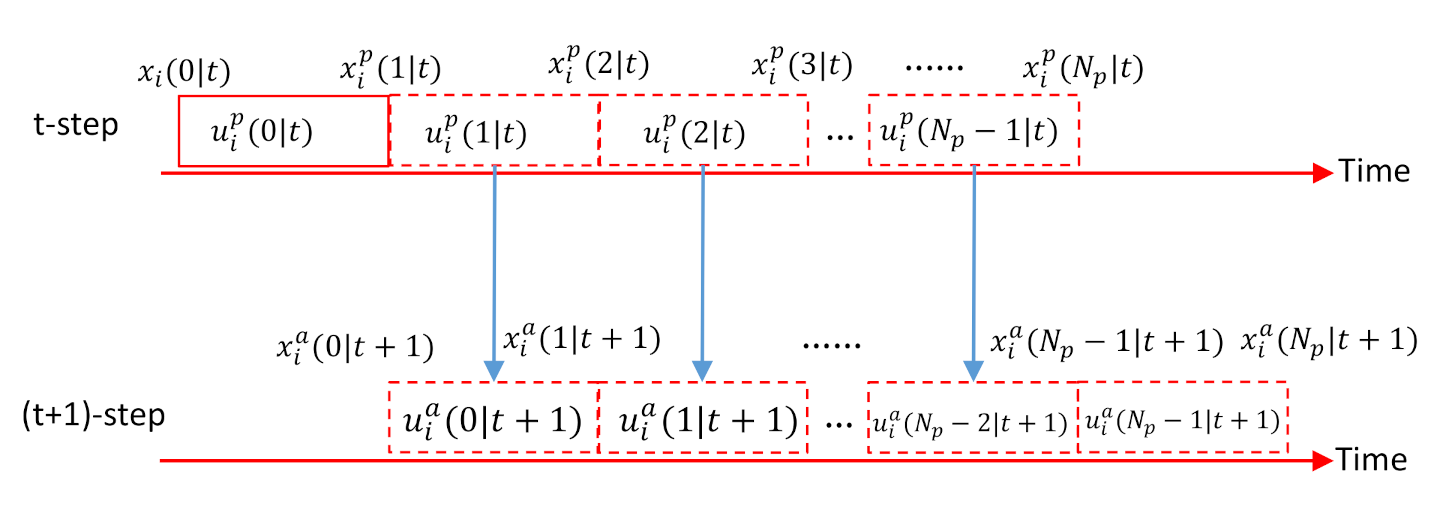
Before presenting the modified DMPC method, two types of variables should be defined over the predictive control horizon t∼. and are the predicted kinetic status and predicted torque input of PM i at time , respectively. and are the assumed kinetic status and assumed torque input of PM i, which are the shifted versions of the predicted variables. The shifting process between predicted variables and assumed variables is shown in Figure 2, i.e.,
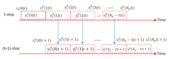
Figure 2.
Basic procedure to construct assumed torque inputs and assumed kinetic status.
The assumed kinetic status is transmitted to downstream PMs. Similarly, PM i receives assumed kinetic status , where represents the neighbor set of PM i at time t. It is worth noting that Formula (12c) makes the PM i always move at a constant speed at the end of the predictive horizon.
3.1. Objective Function
The fuel consumption is supposed to be minimized when a platoon is driving on a flat road, i.e.,
where is the weighting factor of fuel consumption.
Since the short-term predictive horizon cannot effectively solve the problem of the high fuel consumption caused by frequent traffic disturbances, we use the velocities of multiple PMs ahead to smooth out these effects. Only the position of the nearest neighbor PM is used for position tracking because its CAM transmission is more reliable. Since the assumed kinetic status needs to be sent to other vehicles for their motion control, the error between the predicted kinetic status and the assumed kinetic status should be minimized as much as possible. Further, to ensure passenger comfort, the torque input of each PM is as small as possible. Thus, the objective function is modeled as follows
where are the weighting matrices, is the weighting factor of kinetic status. is the assumed kinetic status of the nearest neighbor where PM i received. is the desired kinetic status vector between PM j and PM i.
3.2. Constraints
To ensure road safety, the velocity of PM i is limited as
where is the allowed maximum velocity of PM i. To meet passenger comfort requirement, the acceleration and the acceleration variation are limited:
where , and are the minimum acceleration (i.e., the maximum negative braking acceleration), the maximum acceleration, and the maximum change rate of acceleration, respectively. Due to limited size of braking and driving force, the constraint of control torque is as follows,
where and are the minimum torque and the maximum torque, respectively. To make the DMPC process achieve the kinetic status convergence, similarly to [17], the terminal constraint is considered:
where is the cardinality of set . As mentioned before, the position of PM i only follows the position of the nearest neighbor PM, thereby reducing the impact of traffic perturbations and communication failures. At the end of predictive horizon, the velocity of PM i tracks the average assumed velocities of the neighbor PMs. The terminal constraint (18c) makes PM i move at a constant speed at the end of the predictive horizon.
3.3. DMPC Design
Finally, we formulate the DMPC problem of each PM as
and (15)–(18) hold. This DMPC problem is a nonlinear optimization problem. Several efficient computing techniques such as transforming into 0–1 mixed-integer linear programming problems [22,23], using particle swarm optimization algorithm with multiple dynamic populations [24,25], utilizing particular structure [37], might be employed to solve this DMPC problem. In this paper, we use the optimization toolbox [38] to solve the DMPC problem and verify the performance of the controller. In the future, we will study faster and more efficient algorithms to solve the DMPC problem.
Remark 1.
Since the uncertainty of wireless channels and a limited number of reusable uplink channels, it cannot be guaranteed that each PM has the assumed information of neighbor PMs. To deal with this situation , we use the on-board sensors to obtain the position and the velocity of PM . Supposing that PM is driving at a constant speed, it is consistent with the final kinetic status of the platoon leader. Therefore, when PM i cannot receive any assumed information from the V2V network, it has the following assumed information:
when , the estimated assumed information of PM are used in the DMPC method.
3.4. Safety Mechanism Design
Safety is the most essential factor in platoon control. Because of the uncertainty of wireless channels, a limited number of reusable uplink channels, and the serious traffic perturbations, the DMPC problem may not have a solution, causing platoon control to face a safety problem. In addition, the platoon also faces the safety issue of emergency braking. Thus, a safety control strategy needs to be designed to avoid collision with the preceding vehicle. Due to the unreliability of wireless communication, we use the position and the velocity of PM , which are obtained by on-board sensors for safety mechanism design. The safety mechanism of PM i needs to handle two scenarios (i.e., with or without a solution to the DMPC problem).
3.4.1. Without Solution to the DMPC Problem
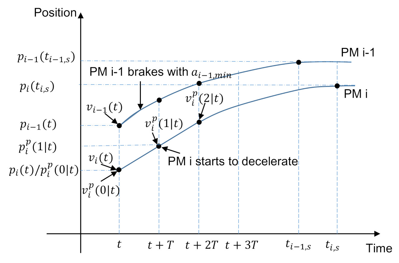
Similar to [30], Figure 3 shows the safety driving analysis when the preceding vehicle suddenly brakes. When PM brakes at the maximum deceleration within the time interval , the stopping position of PM satisfies
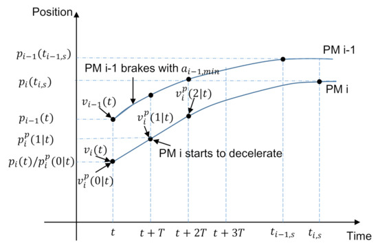
Figure 3.
Safety analysis.
Supposing that PM i drives with constant velocity , the emergency brake of PM can be detected by PM i at the time . Then PM i starts to decelerate with at the time . Therefore, the stop position of PM i can be expressed as
To avoid collision, we have . Considering the uncertainty, serves as the guard interval, and is set to . We call this condition as a safety constraint condition. The safety mechanism of PM i is designed as
When PM i is in the safety constraint area, the controller performs mild deceleration to ensure passenger comfort and fuel economy and make the DMPC problem solvable again. If PM i cannot satisfy the safety constraint, then maximum braking is applied. makes PM i just stop moving.
3.4.2. With Solution to the DMPC Problem
When the DMPC Problem can be solved, the predicted kinetic statuses of PM i can be obtained in the predictive horizon. Based on Figure 3 and Formulas (21) and (22), the stop position of PM i can be expressed as
To avoid collision, our controller must satisfy the safety constraint condition . Therefore, the safety mechanism of PM i is designed as
When PM i is in the safety constraint area, the controller performs the first term of the predicted control sequence, i.e., ; otherwise, the maximum braking is applied.
4. Resource Allocation for Platoon-Based V2V Communication
In high-density vehicular traffic, the reusable uplink channels allocated to the platoon could be limited. The fast channel variations can cause V2V link outage and the CAM loss. Moreover, the traffic perturbations are very serious in high-density traffic flow. As explained in Section 3, a modified DMPC controller was designed to smooth traffic perturbations by using the velocities of multiples PMs ahead. In the case of a limited number of uplink channels that can be reused in the platoon and the uncertainty of wireless channels, how each DMPC controller can obtain the CAMs of multiple PMs is the problem to be solved in this section. We propose an effective resource allocation scheme to increase the CAM broadcast distance of each PM.
4.1. Problem Formulation of Resource Allocation
In each CAM transmission interval, the available Q uplink channels can be reused by platoon-based V2V broadcast links in the coverage of eNB. Due to the half-duplex transceiver mechanism and multiple receivers on one V2V broadcast link, we assume that the CAM transmissions within the platoon occur in different time domains of the CAM transmission interval. To reuse the uplink channel, the platoon-based V2V broadcast link has to meet the following conditions:
where is the minimum ergodic capacity requirement of the CUE, and is the minimum SINR requirement of platoon-based V2V link. evaluates the outage probability of V2V link and is the tolerable outage probability of the V2V link. and represent the maximum transmit power of the PM and CUE, respectively.
To enable the DMPC controller to obtain velocity information of more PMs, the optimization problem can be formulated as
and (26a–d) hold. represents the number of the receivers in broadcast link i range. is determined by (26a–d). represents the weight of PM i state information, and represents the weight of the coverage of broadcast link i. Since the kinetic status of the platoon leader plays a leading role in the platoon, we set to be . Other PMs are set as . We set to indicate the change of coverage of broadcast link. A larger means that there are more receiving PMs in the range of broadcast link i. Therefore, the objective function enables each PM to receive as much broadcast information as possible.
4.2. Solution of the Formulated Problem
The resource allocation problem is a nonconvex optimization problem since its combinatorial nature is related to the channel quality and the number of reusable uplink channels. Inspired by [39], we solve this optimization problem in two steps. Here, platoon-based V2V broadcast link and CUE pairing are marked as V2V-CUE. First, for each V2V-CUE pair, power are allocated to maximize while ensuring the reliability of the V2V link and the requirement of CUE ergodic capacity. Second, by constructing bipartite graph matching, the Hungarian algorithm [40] can be used to solve the resource allocation problem efficiently. To solve the optimization problem, the following lemmas from [39] are used.
Lemma 1.
When the V2V link i reuses uplink channel of CUE q, the reliability constraint (26b) can be translated as follows
Lemma 2.
The optimal power allocation solution for the optimization problem which maximize the ergodic capacity of CUE while ensuring reliability of V2V link is given by
and
where and . Note that by performing a binary search on the function , we can obtain the variable .
Lemma 3.
When the CUE q shares spectrum with the V2V link i, a closed-form expression of the ergodic capacity of CUE q can be defined as and given by
where , and is the first-order exponential integral function.
The detailed derivation of the above lemmas can be seen in [39]. In this paper, when the V2V link reuses the uplink channel of CUE, we need to find the power allocation to maximize with ergodic capacity guaranteed for CUE q and reliability guaranteed for broadcast link i. It is not the same as Lemma 2. However, when is fixed, the optimal power allocation obtained from Lemma 2 can be used to verify that constraints (26a–d) are met. When V2V link reliability is guaranteed and the maximum ergodic capacity cannot meet the constraint conditions, there is no other solution satisfying the constraint (26a–d). Therefore, for broadcast link i and uplink communication of CUE q, we can find the maximum by decreasing the maximum length of broadcast link i iteratively. Since the maximum is determined for each pair of V2V-CUE, the optimization problem (27) can be simplified as
The above optimization problem is a minimum weight matching problem in bipartite graphs. Two disjoint vertex subsets constitute the vertex set of a bipartite graph and the weight of each edge is denoted as . It is worth noting that when is zero, i.e., the V2V broadcast link i cannot reuse the uplink channel of CUE q, we set . The minimum weight matching problem can be solved by using the Hungarian method [40]. In conclusion, the resource allocation scheme can be obtained by Algorithm 1.
| Algorithm 1: Resource Allocation Scheme. |
| Input: Platoon-based V2V broadcast link , uplink channel and corresponding large-scale channel power gain, platoon size . Output: . 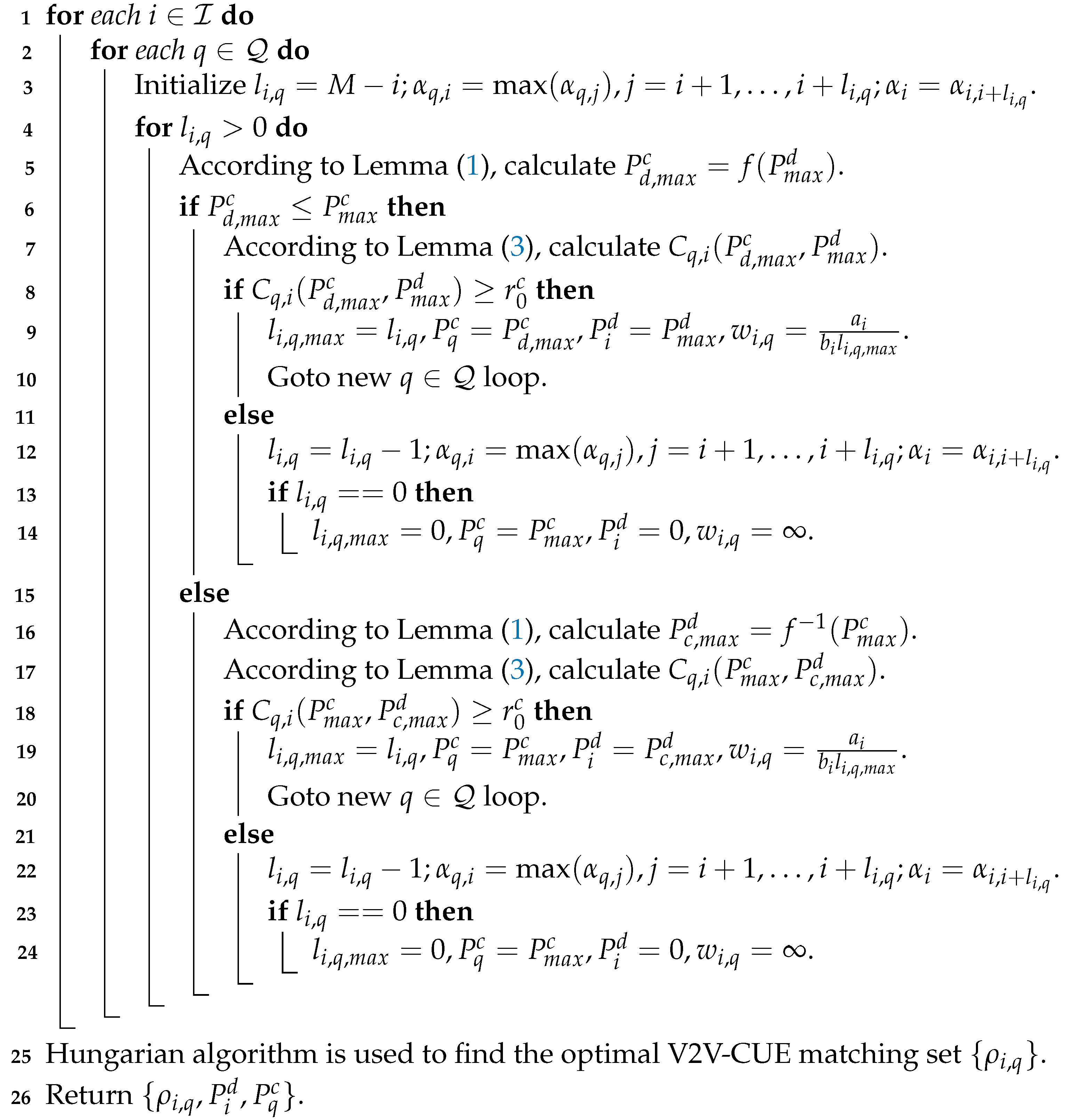 |
Since broadcast link i has multiple receivers, the maximum is determined by decreasing the maximum length of broadcast link i iteratively. Since there are multiple interference channels from CUE to multiple receivers of broadcast link, Lemma 1 uses the maximum channel power gain to ensure that all receivers meet the reliability. Line 3 of Algorithm 1 describes the above process. From Lemma 2, the power allocation for V2V-CUE pair depends on the magnitudes of and . Therefore, Line 5–14 and Line 16–24 in Algorithm 1 correspond to the two cases. Supposing that the channel power gain decreases with the increase in communication link distance, it is beneficial to reduce the algorithm complexity. The assumption implies that the transmission power and make all receivers within the broadcast link range meet V2V reliability. However, the simulation results are calculated using the actual channel information. Supposing an accuracy of is needed, the binary search takes iterations to find . Then the total complexity to compute the power allocation and find maximum for all V2V-CUE pairs is . The Hungarian method is to solve the minimum weight matching problem and obtain the optimal V2V-CUE matching set . Assuming , the upper limit of iterations is . So the total complexity of the algorithm is .
5. Simulation Results and Analysis
5.1. Simulation Settings
In this section, the simulation results are presented to evaluate the proposed modified DMPC method and radio resource allocation scheme. Consider a highway segment with three lanes, which allows one-way traffic from left to right. To ensure the reliability of platoon-based V2V communication, we only consider those CUEs in the same direction lanes for reusing. As shown in Figure 1, the eNB is located at (499 m, −35 m), and the lane width is 4 m. The starting point coordinates of lanes 1, 2, and 3 are (0 m, 0 m), (0 m,4 m), and (0 m, 8 m), respectively. A platoon of ten vehicles is driving on lane 3. According to the spatial Poisson process, other individual vehicles are placed on the lane 1 and lane 2, and the vehicle density is determined by the average speed of 15 m/s. These individual vehicles are driven with an Intelligent Driver Model (IDM) [41], and the generation probability of each lane is 0.6 per second. The high-capacity uplink communications are generated randomly from Q individual vehicles at each resource reallocation, which can be reused by platoon-based V2V communications. To evaluate the traffic perturbation scenario, the speed variation of the leader is given by
To facilitate the comparison of algorithms, the driving distance of the platoon leader under each algorithm remains unchanged. The total simulation time is 35 s. The wireless channel models are specified in [42] and updated every 100 ms. The detailed simulation parameters are summarized in Table 1. We use Matrix Laboratory (MATLAB) to verify the proposed algorithm. From Figure 4, Figure 5, Figure 6, Figure 7, Figure 8 and Figure 9, we show the real-time vehicle kinetic status and real-time wireless communication performance. Table 2 is obtained from an average of 2450 samples (running 7 times, 350 samples each time). Table 3 and Figure 10 are obtained from averaging seven samples. The simulation runs on a PC with Intel i3 CPU, 8G memory, and Windows 7 operating system.

Table 1.
Vehicle dynamic and wireless channel simulation parameters.
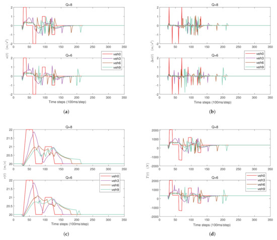
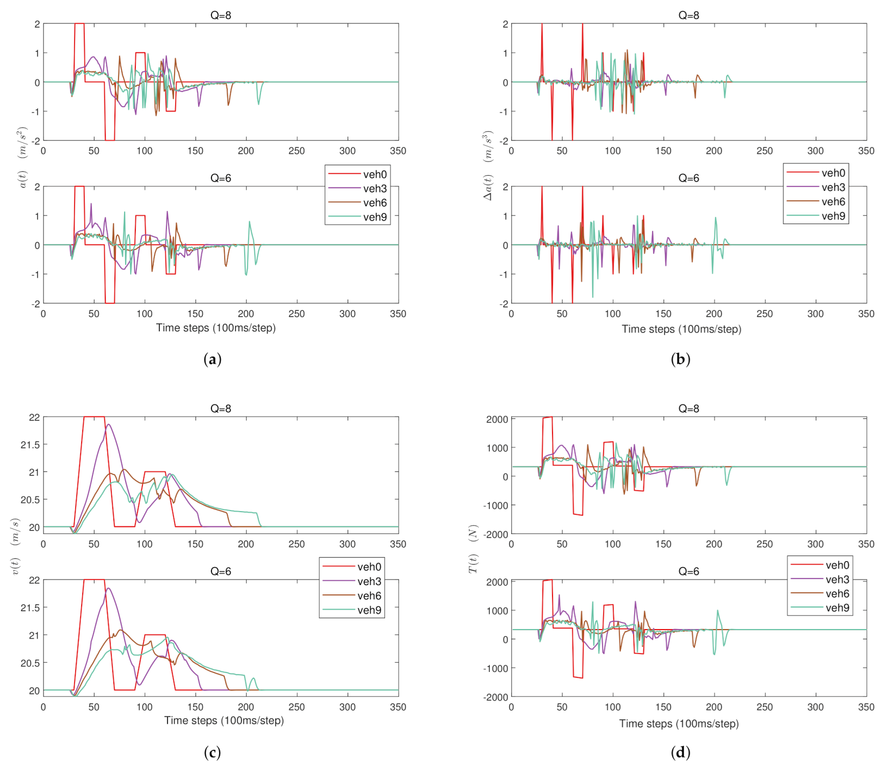
Figure 4.
Vehicle acceleration, rate of vehicle acceleration change, velocity, and torque with different numbers Q of reusable uplink channels. (a) Acceleration; (b) Rate of acceleration change; (c) Velocity; (d) Torque.
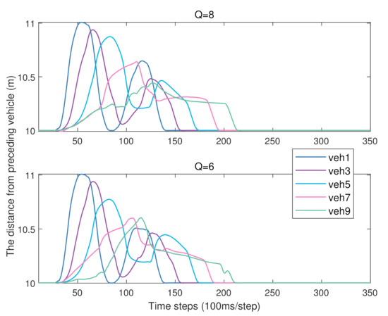
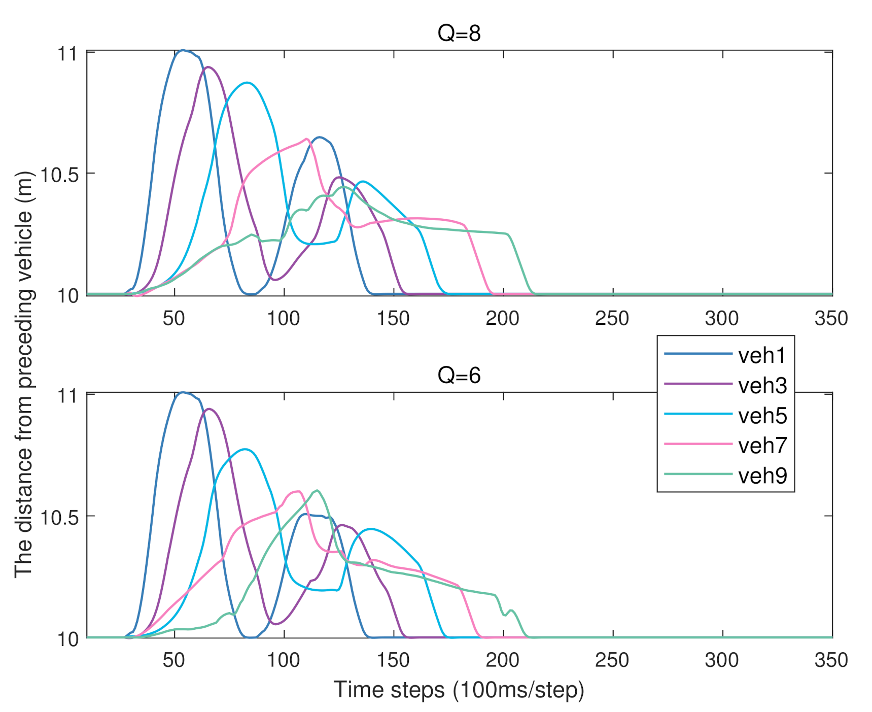
Figure 5.
The distance between the corresponding PM and its predecessor.

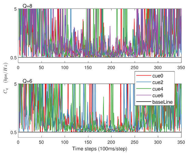
Figure 6.
The ergodic capacities of CUEs when the resource allocation period is 100 ms.
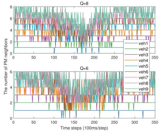
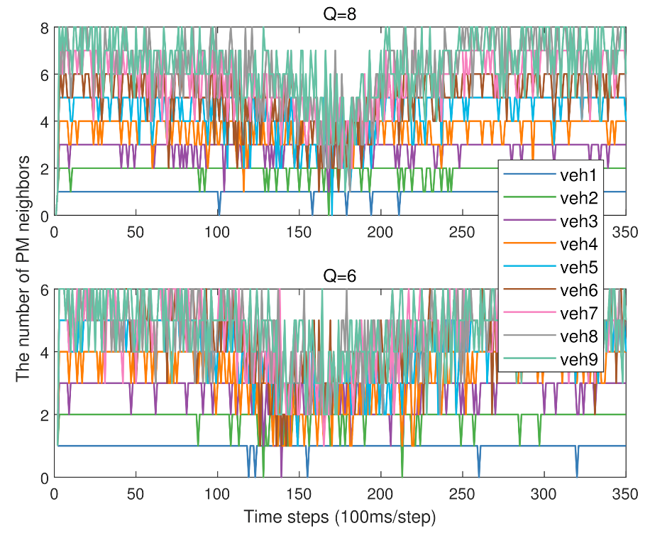
Figure 7.
Changes in the number of PM neighbors.
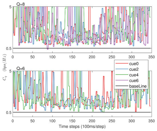
Figure 8.
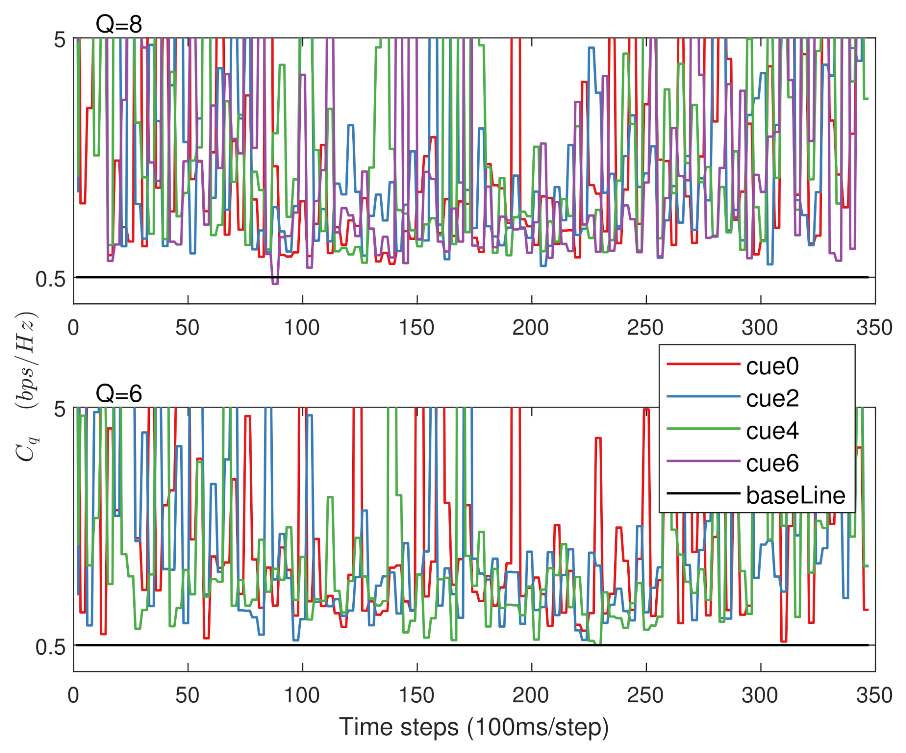
The ergodic capacities of CUEs when the resource allocation period is 300 ms.
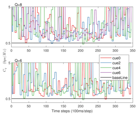
Figure 9.
The ergodic capacities of CUEs when the resource allocation period is 500 ms.
Table 2.
The average number of PM neighbors.
Table 3.
The fuel consumption of vehicle platooning with different resource allocation periods and different numbers of reusable uplink channels.
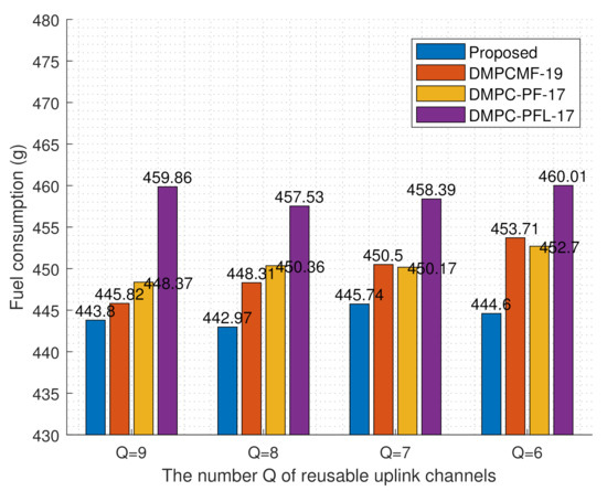
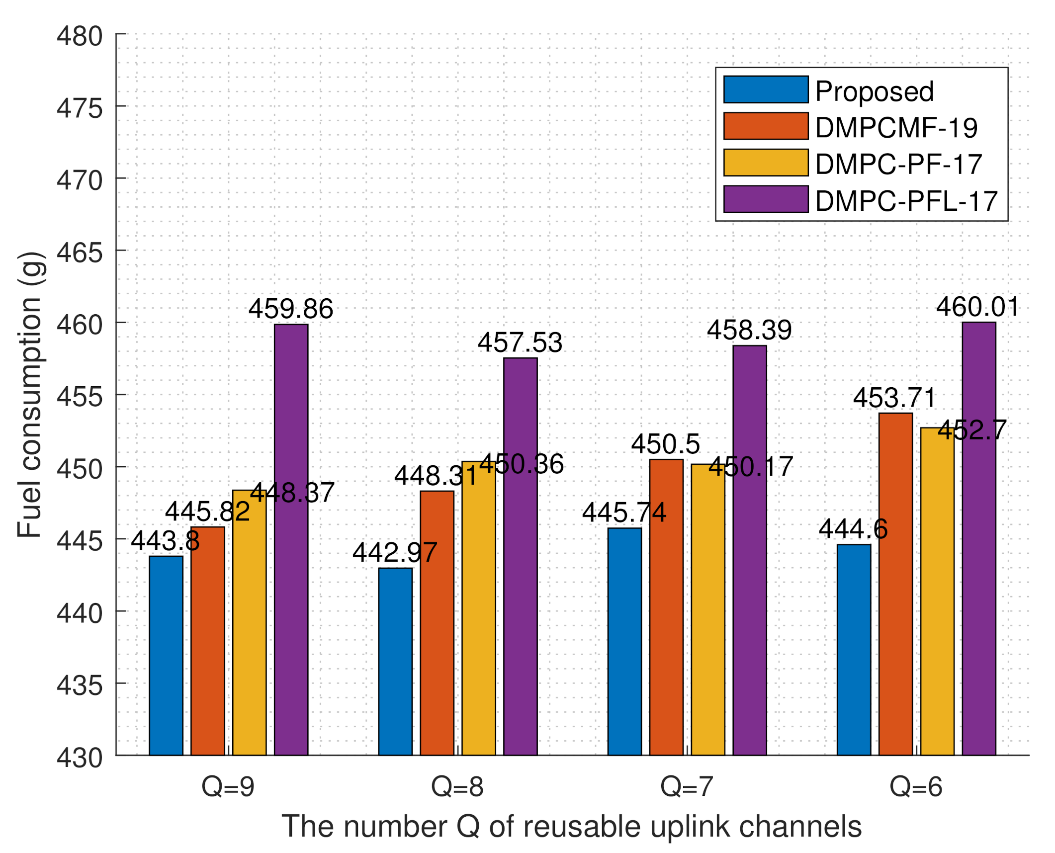
Figure 10.
Comparison of fuel consumption of different algorithms with different numbers of reusable uplink channels.
5.2. Results Analysis
In our simulation, we first evaluate the platoon dynamic performance. Figure 4 shows the accelerations, rates of acceleration change, velocities, and the torques of corresponding PMs in different Q reusable uplink channels. Figure 4a shows that the acceleration values of corresponding PMs are within the acceleration constraint range. In Figure 4b–d, the other three kinetic statuses (i.e., rate of acceleration change, velocity, torque) in the platoon behave the same way as the acceleration. According to Formula (2), there is an approximately linear relationship between acceleration and torque, which can be seen in Figure 4a,d. Moreover, it can be seen in Figure 4 that the kinetic statuses of corresponding PMs can follow the platoon leader and achieve state convergence. The distance between the corresponding PM and its predecessor is described in Figure 5. The final desired distance is 10 m with time headway s and final constant speed 20 m/s. Figure 5 shows that corresponding PMs can reach the final desired distance. According to Formula (6), fuel consumption is related to vehicle velocity and torque. Figure 4c,d show that the succeeding PM has a smaller change in velocity and torque value than the preceding PM. This explains the main reason why the proposed controller can save fuel.
Next, we evaluated the performance of the radio resource allocation algorithm. Figure 6 demonstrates the ergodic capacity of the corresponding CUE when the resource allocation period is 100 ms. It is observed that the ergodic capacity of the corresponding CUE satisfies the baseline requirement. Figure 7 shows the variation in the number of neighbors of each PM. Between the time steps of 150 and 200, the number of neighbors of each PM decreases. This is because the platoon-based V2V broadcast links are close to eNB, which causes strong interference to uplink communications, resulting in the limited broadcast distances of platoon-based V2V communications. Since the channel parameters reported to the eNB require a lot of additional signaling overhead, larger resource allocation periods such as 300 ms and 500 ms are also studied. An appropriate margin should be added to the baseline to ensure that the capacity requirements of CUEs can be met with a larger allocation period. Here, for the resource allocation periods 300 ms and 500 ms, a baseline margin of 0.5 bps/Hz is added to the baseline of 0.5 bps/Hz. Figure 8 and Figure 9 show that most of the CUEs exceed the baseline requirements by a large margin, except for a small number of CUEs that do not meet the ergodic capacity requirements. The comparison between Figure 8 and Figure 9 shows that the ergodic capacity requirements of more CUEs cannot meet the baseline in a larger resource allocation period. This indicates that a larger resource period is not suitable for scenarios with higher capacity requirements. Table 2 shows the average number of PM neighbors under different Q value and resource allocation period in the whole simulation time. It shows that the average number of PM neighbors decreases with a larger allocation period and smaller Q value. The main reason is that to meet the ergodic capacity requirements of CUEs in a larger allocation period, a higher baseline margin is required, and a higher baseline margin limits the broadcast ranges of the platoon-based V2V links.
Finally, we evaluated the fuel consumption performance of the platoon. Table 3 shows fuel consumption of vehicle platooning with different resource allocation periods and different numbers of reusable uplink channels. Although the number of PM neighbors decreases with a larger resource allocation period, their fuel consumption performances are very close. Figure 10 demonstrates fuel consumption of different algorithms with different numbers of reusable uplink channels. DMPC-PF-17 uses constant space strategy and preceding-following topology for platoon driving, which is proposed in [17]. DMPC-PFL-17 uses constant space strategy and preceding-leader-following topology for control [17]. DMPCMF-19 was proposed in [22] to optimize fuel consumption at the predictive control horizon. Here, DMPCMF-19 works with a preceding–following topology. In Figure 10, we know that the proposed scheme has better fuel economy compared with existing schemes. Furthermore, the fuel consumption of the platoon remains stable with a limited number of reusable uplink channels.
6. Conclusions
In this paper, a modified DMPC method is proposed for smoothly responding to traffic perturbations and explicitly handling the constraints of vehicle state and control. To further improve the platoon fuel performance, a radio resource allocation optimization problem to increase the CAM broadcast distance of each PM is proposed. The optimization problem is solved in two steps including maximum V2V broadcast distance and minimum weight matching. Simulation results demonstrate that when the number of reusable uplink channels allocated to the platoon is limited, all PMs can follow the platoon leader and maintain state convergence. Further, the radio resource allocation scheme can increase the distance of platoon-based V2V broadcast while ensuring the ergodic capacity requirement of CUE uplink communication. In the end, by comparing different control algorithms, simulations show that our proposed algorithm has better fuel efficiency.
Notably, the radio resources allocation is assumed to be controlled by eNB in this paper. A further consideration is also needed in scenarios without eNB coverage, especially in high-density scenarios. The direction of future research will be to improve CAM transmission without eNB coverage and in high-density vehicle scenarios. In this paper, we use the existing optimization tool to solve the modified DMPC problem, so the solving efficiency could still be further improved by efficient algorithms. Another research direction will be to study faster and more efficient algorithms to solve the modified DMPC problem. This paper mainly focuses on the study of homogeneous vehicles, which needs to be extended to heterogeneous vehicles in the future. The cross-sectional areas of heterogeneous vehicles will cause different air resistance. Different car brands will have different internal inertia lags, resulting in different dynamic response speeds. These heterogeneous characteristics of the vehicle will limit the use of our proposed controller, which requires further study.
Author Contributions
Conceptualization, Q.W.; methodology, Q.W.; software, Q.W.; validation, Q.W.; formal analysis, Q.W.; investigation, Q.W.; resources, B.-J.H.; data curation, Q.W.; writing—original draft preparation, Q.W.; writing—review and editing, B.-J.H.; visualization, Q.W.; supervision, B.-J.H.; project administration, B.-J.H.; funding acquisition, B.-J.H. All authors have read and agreed to the published version of the manuscript.
Funding
This work was funded in part by the National Natural Science Foundation of China (NSFC) under grant no. 61871193, in part by the Key Project of Guangdong Natural Science Foundation under grant no. 2018B030311049, and in part by the Research and Development Program of Key Science and Technology Fields in Guangdong Province under grant no. 2019B090912001.
Institutional Review Board Statement
Not applicable.
Informed Consent Statement
Not applicable.
Conflicts of Interest
The authors declare no conflict of interest.
References
- Jia, D.; Lu, K.; Wang, J.; Zhang, X.; Shen, X. A Survey on Platoon-based Vehicular Cyber-Physical Systems. IEEE Commun. Surv. Tutor. 2016, 18, 263–284. [Google Scholar] [CrossRef] [Green Version]
- Vukadinovic, V.; Bakowski, K.; Marsch, P.; Garcia, I.D.; Xu, H.; Sybis, M.; Sroka, P.; Wesolowski, K.; Lister, D.; Thibault, I. 3GPP C-V2X and IEEE 802.11p for Vehicle-to-Vehicle Communications in Highway Platooning Scenarios. Ad Hoc Netw. 2018, 74, 17–29. [Google Scholar] [CrossRef]
- Molina-Masegosa, R.; Gozalvez, J. LTE-V for Sidelink 5G V2X Vehicular Communications: A New 5G Technology for Short-Range Vehicle-to-Everything Communications. IEEE Veh. Technol. Mag. 2017, 12, 30–39. [Google Scholar] [CrossRef]
- Chen, S.; Hu, J.; Shi, Y.; Zhao, L. LTE-V: A TD-LTE-Based V2X Solution for Future Vehicular Network. IEEE Internet Things J. 2016, 3, 997–1005. [Google Scholar] [CrossRef]
- Mazzola, M.; Schaaf, G.; Stamm, A.; Kurner, T. Safety-Critical Driver Assistance Over LTE: Toward Centralized ACC. IEEE Trans. Veh. Technol. 2016, 65, 9471–9478. [Google Scholar] [CrossRef]
- Campolo, C.; Molinaro, A.; Araniti, G.; Berthet, A.O. Better Platooning Control Toward Autonomous Driving: An LTE Device-to-Device Communications Strategy That Meets Ultralow Latency Requirements. IEEE Veh. Technol. Mag. 2017, 12, 30–38. [Google Scholar] [CrossRef] [Green Version]
- Peng, H.; Li, D.; Ye, Q.; Abboud, K.; Zhao, H.; Zhuang, W.; Shen, X. Resource Allocation for Cellular-based Inter-Vehicle Communications in Autonomous Multiplatoons. IEEE Trans. Veh. Technol. 2017, 66, 11249–11263. [Google Scholar] [CrossRef]
- Wen, Q.; Hu, B.J.; Zheng, L. Outage-Constrained Device-to-Device Links Reuse Maximization and Its Application in Platooning. IEEE Wirel. Commun. Lett. 2019, 8, 1635–1638. [Google Scholar] [CrossRef]
- Giambene, G.; Rahman, M.S.; Vinel, A. Analysis of V2V Sidelink Communications for Platoon Applications. In Proceedings of the 2020 IEEE International Conference on Communications (ICC), Dublin, Ireland, 7–11 June 2020; pp. 1–6. [Google Scholar] [CrossRef]
- Hegde, S.; Blume, O.; Shrivastava, R.; Bakker, H. Enhanced Resource Scheduling for Platooning in 5G V2X Systems. In Proceedings of the 2019 IEEE 2nd 5G World Forum (5GWF), Dresden, Germany, 30 September–2 October 2019; pp. 108–113. [Google Scholar] [CrossRef]
- 3GPP TS 22.186 V16.2.0, Technical Specification Group Services and System Aspects. Service Requirements for Enhanced V2X Scenarios, Release 16. 2019. Available online: https://portal.3gpp.org/desktopmodules/Specifications/SpecificationDetails.aspx?specificationId=3180 (accessed on 9 September 2021).
- Naus, G.J.L.; Vugts, R.P.A.; Ploeg, J.; Molengraft, M.J.G.; Steinbuch, M. String-Stable CACC Design and Experimental Validation: A Frequency-Domain Approach. IEEE Trans. Veh. Technol. 2010, 59, 4268–4279. [Google Scholar] [CrossRef]
- Ge, J.I.; Orosz, G. Optimal Control of Connected Vehicle Systems with Communication Delay and Driver Reaction Time. IEEE Trans. Intell. Transp. Syst. 2017, 18, 2056–2070. [Google Scholar] [CrossRef]
- Fernandes, P.; Nunes, U. Platooning with IVC-Enabled Autonomous Vehicles: Strategies to Mitigate Communication Delays, Improve Safety and Traffic Flow. IEEE Trans. Intell. Transp. Syst. 2012, 13, 91–106. [Google Scholar] [CrossRef]
- Dunbar, W.B.; Caveney, D.S. Distributed Receding Horizon Control of Vehicle Platoons: Stability and String Stability. IEEE Trans. Automat. Control 2012, 57, 620–633. [Google Scholar] [CrossRef]
- Liu, P.; Kurt, A.; Ozguner, U. Distributed Model Predictive Control for Cooperative and Flexible Vehicle Platooning. IEEE Trans. Control Syst. Technol. 2019, 27, 1115–1128. [Google Scholar] [CrossRef]
- Zheng, Y.; Li, S.E.; Li, K.; Borrelli, F.; Hedrick, J.K. Distributed Model Predictive Control for Heterogeneous Vehicle Platoons Under Unidirectional Topologies. IEEE Trans. Control Syst. Technol. 2017, 25, 899–910. [Google Scholar] [CrossRef] [Green Version]
- Lu, L.; He, D.; Yu, S.; Dong, S. Distributed Predictive Control for String Stability of Heterogonous Vehicle Platoons with Multiple Communication Topologies. In Proceedings of the 2019 Chinese Control Conference (CCC), Guangzhou, China, 27–30 July 2019; pp. 2930–2935. [Google Scholar] [CrossRef]
- Li, K.; Bian, Y.; Li, S.; Xu, B.; Wang, J. Distributed Model Predictive Control of Multi-Vehicle Systems with Switching Communication Topologies. Transp. Res. Part C Emerg. Technol. 2020, 118, 102717. [Google Scholar] [CrossRef]
- Tapli, T.; Kiran, U. A Modified Distributed Model Predictive Control Approach for Handling Vehicular Platoon Communication Problems. In Proceedings of the 2020 IEEE 23rd International Conference on Intelligent Transportation Systems (ITSC), Rhodes, Greece, 20–23 September 2020; pp. 1–6. [Google Scholar] [CrossRef]
- Turri, V.; Besselink, B.; Johansson, K.H. Cooperative Look-Ahead Control for Fuel-Efficient and Safe Heavy-Duty Vehicle Platooning. IEEE Trans. Control Syst. Technol. 2017, 25, 12–28. [Google Scholar] [CrossRef] [Green Version]
- Zhai, C.; Liu, Y.; Luo, F. A Switched Control Strategy of Heterogeneous Vehicle Platoon for Multiple Objectives with State Constraints. IEEE Trans. Intell. Transp. Syst. 2019, 20, 1883–1896. [Google Scholar] [CrossRef]
- Zhai, C.; Luo, F.; Liu, Y. Cooperative Look-Ahead Control of Vehicle Platoon for Maximizing Fuel Efficiency Under System Constraints. IEEE Access 2018, 6, 37700–37714. [Google Scholar] [CrossRef]
- Zhai, C.; Luo, F.; Liu, Y. Cooperative Look-Ahead Control of Vehicle Platoon Travelling on A Road with Varying Slopes. IET Intell. Transp. Syst. 2019, 13, 376–384. [Google Scholar] [CrossRef]
- Zhai, C.; Luo, F.; Liu, Y.; Chen, Z. Ecological Cooperative Look-Ahead Control for Automated Vehicles Travelling on Freeways with Varying Slopes. IEEE Trans. Veh. Technol. 2019, 69, 1208–1221. [Google Scholar] [CrossRef]
- Zhai, C.; Chen, X.; Yan, C.; Liu, Y.; Li, H. Ecological Cooperative Adaptive Cruise Control for a Heterogeneous Platoon of Heavy-Duty Vehicles with Time Delays. IEEE Access 2020, 8, 146208–146219. [Google Scholar] [CrossRef]
- Zhai, C.; Luo, F.; Liu, Y. Cooperative Power Split Optimization for a Group of Intelligent Electric Vehicles Travelling on a Highway with Varying Slopes. IEEE Trans. Intell. Transp. Syst. 2020, in press. [Google Scholar] [CrossRef]
- Mei, J.; Zheng, K.; Zhao, L.; Lei, L.; Wang, X. Joint Radio Resource Allocation and Control for Vehicle Platooning in LTE-V2V Network. IEEE Trans. Veh. Technol. 2018, 67, 12218–12230. [Google Scholar] [CrossRef]
- Zeng, T.; Semiari, O.; Saad, W.; Bennis, M. Joint Communication and Control for Wireless Autonomous Vehicular Platoon Systems. IEEE Trans. Commun. 2019, 67, 7907–7922. [Google Scholar] [CrossRef] [Green Version]
- Hong, C.; Shan, H.; Song, M.; Zhuang, W.; Xiang, Z.; Wu, Y.; Yu, X. A Joint Design of Platoon Communication and Control Based on LTE-V2V. IEEE Trans. Veh. Technol. 2020, 69, 15893–15907. [Google Scholar] [CrossRef]
- Gonçalves, T.R.; Varma, V.S.; Elayoubi, S.E. Vehicle Platooning Schemes Considering V2V Communications: A Joint Communication/Control Approach. In Proceedings of the 2020 IEEE Wireless Communications and Networking Conference (WCNC), Seoul, Korea, 25–28 May 2020; pp. 1–6. [Google Scholar] [CrossRef]
- Sciarretta, A.; Nunzio, G.; Ojeda, L.L. Optimal Ecodriving Control: Energy-Efficient Driving of Road Vehicles as an Optimal Control Problem. IEEE Control Syst. 2015, 35, 71–90. [Google Scholar] [CrossRef] [Green Version]
- He, C.R.; Maurer, H.; Orosz, G. Fuel Consumption Optimization of Heavy-Duty Vehicles with Grade, Wind, and Traffic Information. J. Comput. Nonlinear Dyn. 2016, 11, 1–12. [Google Scholar] [CrossRef] [Green Version]
- He, C.R.; Orosz, G. Saving Fuel Using Wireless Vehicle-to-Vehicle Communication. In Proceedings of the 2017 American Control Conference (ACC), Seattle, WA, USA, 24–26 May 2017; pp. 4946–4951. [Google Scholar] [CrossRef]
- He, C.R.; Ge, J.I.; Orosz, G. Fuel Efficient Connected Cruise Control for Heavy-Duty Trucks in Real Traffic. IEEE Trans. Control Syst. Technol. 2019, 28, 2474–2481. [Google Scholar] [CrossRef]
- Chehardoli, H.; Ghasemi, A.; Najafi, A. Centralized and Decentralized Distributed Control of Longitudinal Vehicular Platoons with Non-Uniform Communication Topology. Asian J. Control 2019, 21, 2691–2699. [Google Scholar] [CrossRef]
- Wang, Y.; Boyd, S. Fast Model Predictive Control Using Online Optimization. IEEE Trans. Control Syst. Technol. 2010, 18, 267–278. [Google Scholar] [CrossRef] [Green Version]
- Find Minimum of Constrained Nonlinear Multivariable Function. Available online: https://www.mathworks.com/help/optim/ug/fmincon.html (accessed on 9 September 2021).
- Liang, L.; Li, G.Y.; Xu, W. Resource Allocation for D2D-Enabled Vehicular Communications. IEEE Trans. Commun. 2017, 65, 3186–3197. [Google Scholar] [CrossRef]
- West, D.B. Introduction to Graph Theory, 2nd ed.; Prentice Hall: Upper Saddle River, NJ, USA, 2001; pp. 125–130. [Google Scholar]
- Treiber, M.; Kesting, A. Traffic Flow Dynamics: Data Models and Simulation; Springer: Berlin, Germany, 2013; pp. 187–204. [Google Scholar] [CrossRef]
- 3GPP TR 36.885 V14.0.0, Technical Specification Group Radio Access Network. Study on LTE-Based V2X Services, Release 14. 2016. Available online: https://portal.3gpp.org/desktopmodules/Specifications/SpecificationDetails.aspx?specificationId=2934 (accessed on 22 September 2021).

Publisher’s Note: MDPI stays neutral with regard to jurisdictional claims in published maps and institutional affiliations. |
© 2021 by the authors. Licensee MDPI, Basel, Switzerland. This article is an open access article distributed under the terms and conditions of the Creative Commons Attribution (CC BY) license (https://creativecommons.org/licenses/by/4.0/).