Article

Implementation and Validation of Hybrid Control for a DFIG Wind Turbine Using an FPGA Controller Board

1
LIMAS Laboratory, Faculty of Sciences Dhar El Mahraz, Sidi Mohammed Ben Abdellah University, Fez 30000, Morocco
2
Engineering, Systems and Applications Laboratory, ENSA, SMBA University, Fez 30000, Morocco
3
Department of Computer Science, College of Computers and Information Technology, Taif University, P.O. Box 11099, Taif 21944, Saudi Arabia
*
Authors to whom correspondence should be addressed.
Electronics 2021, 10(24), 3154; https://doi.org/10.3390/electronics10243154
Submission received: 4 November 2021 / Revised: 10 December 2021 / Accepted: 13 December 2021 / Published: 17 December 2021

Abstract

:
In this study, a novel control approach for a doubly-fed induction generator (DFIG) is developed and applied to improve the system’s dynamic response and performance for providing high energy quality while avoiding harmonic accumulations. Because of its ease of implementation, field-oriented control (FOC) is frequently used. This control has great sensitivity to the machine’s parametric variations. For this reason, adaptive Backstepping control (ABC) is capable of preserving almost all of the performance and robustness properties. However, its analytical formulation has a problem. To overcome these disadvantages, the hybrid control (HC) is developed and verified to enable rapid response, complete reference tracking, and appropriate dynamic behavior with a low ripple level. This control is a combination of FOC’s and ABC’s control laws. The prepared control is explored by simulation testing using Matlab/Simulink and practical implementation using an FPGA board with actual turbine settings and a real wind profile of Dakhla City, Morocco. The results of hardware simulation show the efficacy of the HC in terms of speed and robustness, with a total harmonic distortion THD = 0.95, a value of THD that reveals the quality of the energy injected into the grid.

1. Introduction

Nowadays, significant effort is being made to find a source of production of renewable energy as an alternative resource to secure fossil fuels while protecting the environment [1]. Wind energy technology has received considerable attention in recent years in this context, owing to its many benefits, such as low cost, ease of deployment, and maintenance [2,3].
Despite the advantages of the wind energy conversion system, it suffers from instability and nonlinearity, resulting from the fluctuating nature of the wind, which can create some problems in the grid, such as a shock. To overcome these problems, the system requires robust controllers that can enable it to face the internal parametric changes and external disturbances and also achieve adequate performance under different operation conditions. For these reasons, several studies and algorithms have been applied to enhance the performance of WECS [4,5,6]. The vector control strategy based on the classic PI controller is considered one of the well-known controls of (WECS) that are used to solve the current–voltage coupling problem in the system. However, this control is sensitive to the parametric changes of the machine.
For this reason, other controls have been proposed in the literature. According to [7], sliding mode control (SMC) is a suitable approach for controlling the DFIG because of its durability. However, it suffers from chattering phenomena. Alami et al. [8] proposed direct power control (DPC), which is characterized by its detachment from the internal parameters of the machine, but the hysteresis comparators remain the major drawback of this control. To overcome all deficiencies discussed previously, the nonlinear Backstepping approach is chosen based on its performances, simple implementation, and robustness. A good tracking response is also ensured, and the system’s stability is obtained by employing the Lyapunov function [9,10].
Backstepping operates using a switching-table-based algorithm to regulate the active and reactive power. Although it provides better control over the decoupling between the active and reactive power and simple algorithm implementation, it suffers from high power ripples, which can reduce the signal’s quality distributed to the grid [11]. To avoid all these problems, several scientific researchers have proposed a series of nonlinear control methods to improve the robustness of the studied system [12].
This article discusses the control design of DFIG. The particularity of this study is that it presents a novel controller structure that is distinct from the majority of sliding-mode-control-based PMSG wind turbine systems. The controller can sustain steady transient performance in the presence of external disturbances, handle any change in the wind speed rapidly and smoothly, and enhance the quality of the electrical energy delivered. Additionally, the validation of the proposed control was analyzed according to the stability, robustness, rapidity, and efficiency of the system, as well as the signal quality sent to the grid.
As a result, the hybrid drive is developed in this article to improve the dynamic power response of the DFI generator and minimize the ripples of its currents when injected into the grid. Furthermore, the planned control diagram is built in real-time using the Nexys 2 FPGA board to verify the experimental model.
The primary contributions of this work include developing the Backstepping control rule, which is based on Lyapunov’s theorem; ensuring decoupling between the DFIG command variables; and improving system efficiency and robustness. Experimental validation of the approach proposed using the real-time interface connected to the Nexys 2 FPGA board is also included. For this purpose, this article is divided as follows: presentation of the model of the wind turbine system conversion chain; modeling and design of the adaptive Backstepping control technique; validation of the model proposed on Matlab/Simulink and also by a co-simulation with an implementation on the FPGA target; and finally, analysis and interpretation of the results.

2. System Modeling

2.1. Wind Turbine

A wind turbine’s principal purpose is to convert kinetic energy from the wind into mechanical energy. The wind’s mechanical power (Pmec) is employed to express it. In addition, this power is dependent on a variety of parameters, including the wind speed V (m/s), the density of air ρ, the surface S (m2), and the power coefficient Cp. Moreover, the torque Tmec (Nm) is expressed by dividing the mechanical power by the turbine speed t (rad/s). They may be mathematically represented as [13]
P m e c = 1 2 ρ . S . C p ( λ , β ) . v 3 T m e c = P m e c Ω t = 1 2 ρ . S . C p ( λ , β ) . v 3 . 1 Ω t
The power coefficient Cp (λ,β) is: [14]:
C p λ , β = c 1 . c 2 . 1 A c 3 . β c 4 . e c 5 1 A + c 6 . λ
with c1 = 0.5872, c2 = 116, c3 = 0.4, c4 = 5, c5 = 21, c6 = 0.0085, and β = 0.

2.2. DFIG

In the dq reference frame of the DFIG machine, the stator and rotor voltage space vector equations, currents equations, and magnetic equations are expressed, respectively, as follows [15]:
V s d = R s . I s d + d ϕ s d d t ω s . ϕ s q V s q = R s . I s q + d ϕ s q d t + ω s . ϕ s d V r d = R r . I r d + d ϕ r d d t ω r . ϕ r q V r q = R r . I r q + d ϕ r q d t + ω r . ϕ r d
I s d = 1 σ . L s . ϕ s d M σ . L r . ϕ s d I s q = 1 σ . L s . ϕ s q M σ . L s . L r . ϕ s q I r d = 1 σ . L r . ϕ r d M σ . L r . L s . ϕ s d I r q = 1 σ . L r . ϕ r q M σ . L r . L s . ϕ s q
ϕ s d = L s . I s d + M . I r d ϕ s q = L s . I s q + M . I r q ϕ r d = L r . I r d + M . I s d ϕ r q = L r . I r q + M . I s q
The expressions of stator and rotor active:
P s = V s d . I s d + V s q . I s q Q s = V s q . I s d V s d . I s q P r = V r d . I r d + V r q . I r q Q r = V r q . I r d V r d . I r q
The Torque equation is expressed as a function of magnetic components:
T e m = P ϕ r d . ϕ s q ϕ r q . ϕ s d
where Rs and Rr are the stator resistance and the rotor resistance, respectively, and Ls, Lr, and M are the stator, rotor, and mutual inductance, respectively. Additionally, d and q denote the dq axes frame, while s and r denote stator and rotor, respectively.

3. Hybrid Control

The primary goal of our adaptative Backstepping approach is to run the wind turbine at full mechanical power. This requires checking the stator’s active powers Ps and reactive powers Qs (Equation (6)) according to [16,17]:
d Ω d t = p J . V s ϕ s q . P s + p J . V s ϕ s d . Q s 1 J T m d P s d t = 3 2 . σ . L s . L r 2 3 R s . L r + R r . L s P s + R r + ω r . L r V s d . ϕ s d + V s q . ϕ s q + M V s d . V r d + V s q . V r q + L r . V s 2 ω s . Q s d Q s d t = 3 2 . σ . L s . L r 2 3 R s . L r + R r . L s Q s + R r + ω r . L r V s d . ϕ s d + V s q . ϕ s q + M V r d + V r q V s d . + ω s . P s
Because of the coupling between the active and reactive power, it is evident that the dynamic model Equation (8) is strongly nonlinear. For a study of this equation, use the Lyapunov function [18,19], which is divided into two steps:
Control of the speed [20]:
V 1 = 1 2 e Ω 2
Control of the powers:
V 2 = 1 2 e P s 2 + e Q s 2
where
e Ω = Ω r e f Ω e P s = P s _ r e f P s e Q s = Q s _ r e f Q s
To ensure the stability of the system, it is necessary to guarantee the negativity of the derivative of the Lyapunov (V1 and V2) function. For this, we define a positive constant “k” in the derivative of Equations (9) and (10), such that
V ˙ 1 = K Ω . e Ω 2 + e Ω K Ω . e Ω p 2 J . V s ϕ s q . P s + p 2 J . V s ϕ s d . Q s p J T m V ˙ 2 = K Ω . e Ω 2 K P s . e P s 2 K Q s . e Q s 2 + e Ω K Ω . e Ω p 2 J . V s ϕ s q . P s + p 2 J . V s ϕ s d . Q s p J T m + e P s K P s . e P s 3 2 . σ . L s . L r 2 3 R s . L r + R r . L s P s + R r + ω r . L r V s d . ϕ s d + V s q . ϕ s q + M V s d . V r d + V s q . V r q + L r . V s 2 ω s . Q s + e Q s K Q s . e Q s 3 2 . σ . L s . L r 2 3 R s . L r + R r . L s Q s + R r + ω r . L r V s d . ϕ s d + V s q . ϕ s q + M V r d + V r q V s d . + ω s . P s
After the mathematical calculation, we consider the active and reactive powers as virtual inputs:
Q s _ r e f = Q s P s _ r e f = 1 p 2 J . V s . ϕ s q K Ω e Ω + p 2 J . V s ϕ s d . Q s _ r e f p J T m
We also consider the control’s laws of the real machine:
V r d = 1 V s d 1 M 2 . σ . L s . L r 3 K P s . e P s ω s . Q s 2 3 R s . L r + R r . L s P s + R r + ω r . L r V s d . ϕ s d + V s q . ϕ s q + L r . V s 2 V r q = 1 V s d M 2 . σ . L s . L r 3 K Q s . e Q s + ω s . P s 2 3 R s . L r + R r . L s Q s + R r + ω r . L r V s d . ϕ s d + V s q . ϕ s q
where K > 0, KPs > 0, and KQs > 0.
We get the negativity of the derivative V1 and V2:
V ˙ 1 = K Ω . e Ω 2 0 V ˙ 2 = K Ω . e Ω 2 K P s . e P s 2 K Q s . e Q s 2 0
This equation shows the asymptotic stability of the origin in the equations of the system of the DFI generator.

4. FPGA Implementation

To adjust the functionality of the nonlinear control algorithm, we created a functional model for the adaptive Backstepping control using the Xilinx “SYSTEM*GENERATOR” environment, which is compatible with Matlab and Simulink [13,14]. This is loaded into the FPGA memory. Control structures are designed using computer-aided design (CAD) tools. The entry is done visually or using a high-level hardware description language, such as Hardware Description Language (HDL), Very High-Speed Integrated Hardware Description Language (VHDL), or Verilog. These two languages are standardized and provide the designer alternative degrees of description, as well as the benefit of being compatible with all previously introduced FPGA technologies [20,21]. Figure 1 depicts the many processes of programming an FPGA.
The generator system allows you to configure the type of FPGA board used, as well as the type of programming language (VHDL or Verilog), and then it generates the code necessary for it to be implemented in the FPGA board.
Figure 2 illustrates the generator system, which is composed of several blocks:
  • Backstepping control blocks: The first block is for controlling the active and reactive power of the stator and the second for the control laws Vrd and Vrq.
  • Calculation block: This block is used to calculate from the measured currents and voltages: the active power, the reactive power, the magnetic fluxes of the stator, the rotor pulsation, and the stator pulsation.
  • Measuring block: This block contains ADC interfaces that allow the connection between the FPGA and the analog-to-digital converter, which allows the currents to be acquired from a Hall Effect sensor.
  • PWM block: This block is used to generate the control signals Sa, Sb, and Sc of the rotor side converters. The Timing block controls the start and end of each block, which makes it possible to refresh the reference voltages at the start of each sampling period.

5. Hardware Co-Simulation

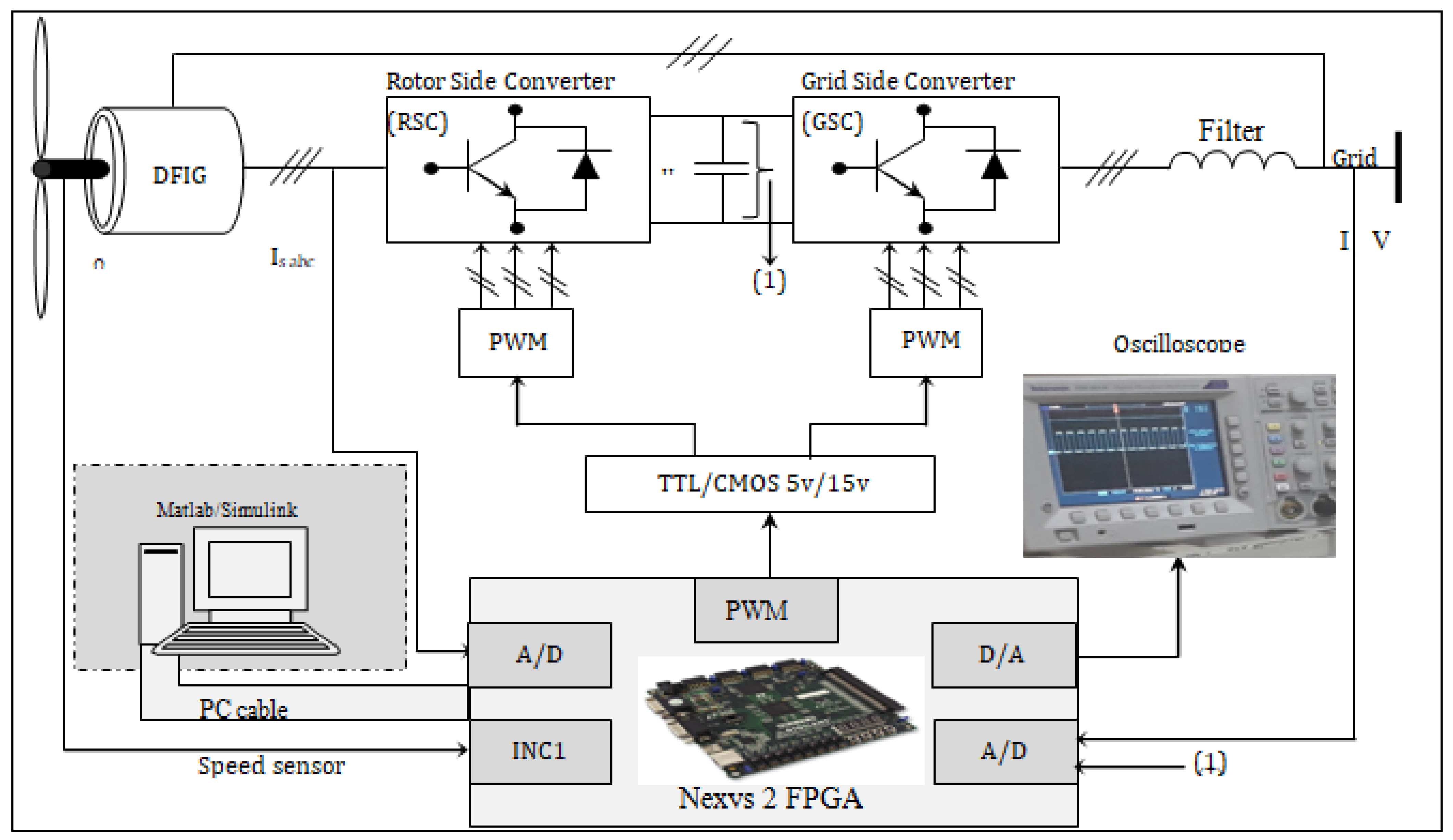
Follow-up tests and robustness tests are given for experimental validation of the proposed control model. The sample period for the Nexys 2 board is Ts = 5 s, and the frequency connected to the FPGA is 50 Mhz. The Nexys 2 board controls digital I/O using TTL logic voltage levels (0–5 V), while the IGBT drivers operate in CMOS logic (0–15 V), necessitating the need for a control board (5–15 V) interface optimized for adaptability and galvanic isolation. The functional diagram of the Nexys 2 board with the DFI generator is shown in Figure 3 and Figure 4.

6. Experimental Results and Discussions

To evaluate the influence of the command on the system and to highlight the objectives discussed in the introduction part, several tests have been performed and discussed.

6.1. Performance Test Static

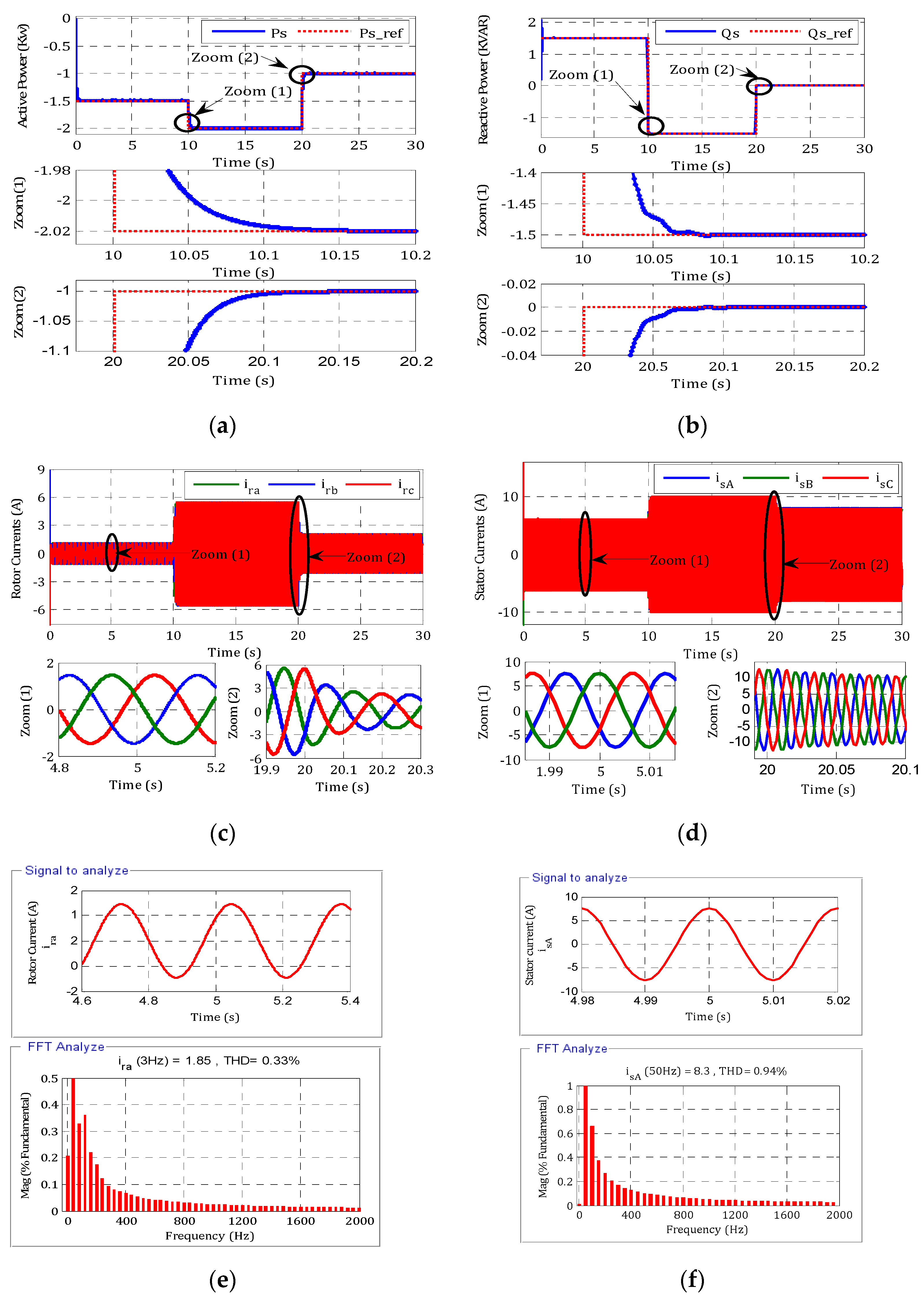
This initial test comprises imposing steps of active and reactive power while the wind speed is set at 12 m/s. This test allows us to verify the performance of the system and the decoupling of the powers created by the DFI generator when the power setpoints change, the parameters of the system is mentioned in Table A1 and Table A2.
Based on these results, we note that (Figure 5):
  • The active and reactive power tracking test is always carried out with high performance.
  • The active power is always negative, which means that the MADA is operating in generator mode and is supplying power to the network.
  • The reactive power control allows us to have either negative or positive reactive power (capacitive or inductive behavior). The sizes ordered perfectly follow their references with a static error of εs = 0.067%.
  • The response of the active and reactive power is aperiodic, with:
    Response time of tr(Ps) = 170 ms and tr(Qs) = 50 ms
    Variation band of ∆Ps = ±5 W and ∆Qs = ±5 VAR.
  • The three-phase stator and rotor currents respond effectively to the torque variations; they are proportional to the active power provided.
  • The current has a sinusoidal form with a frequency of 50 Hz for the stator current alongside the rotor current frequency, which is stabilized at 3 Hz at time t = 4.8 s to an imposed speed of 1800 tr/min.
  • The harmonic distortion is related to 0.33% for the rotor current and 0.94% for the stator current.

6.2. Performance Test Dynamic

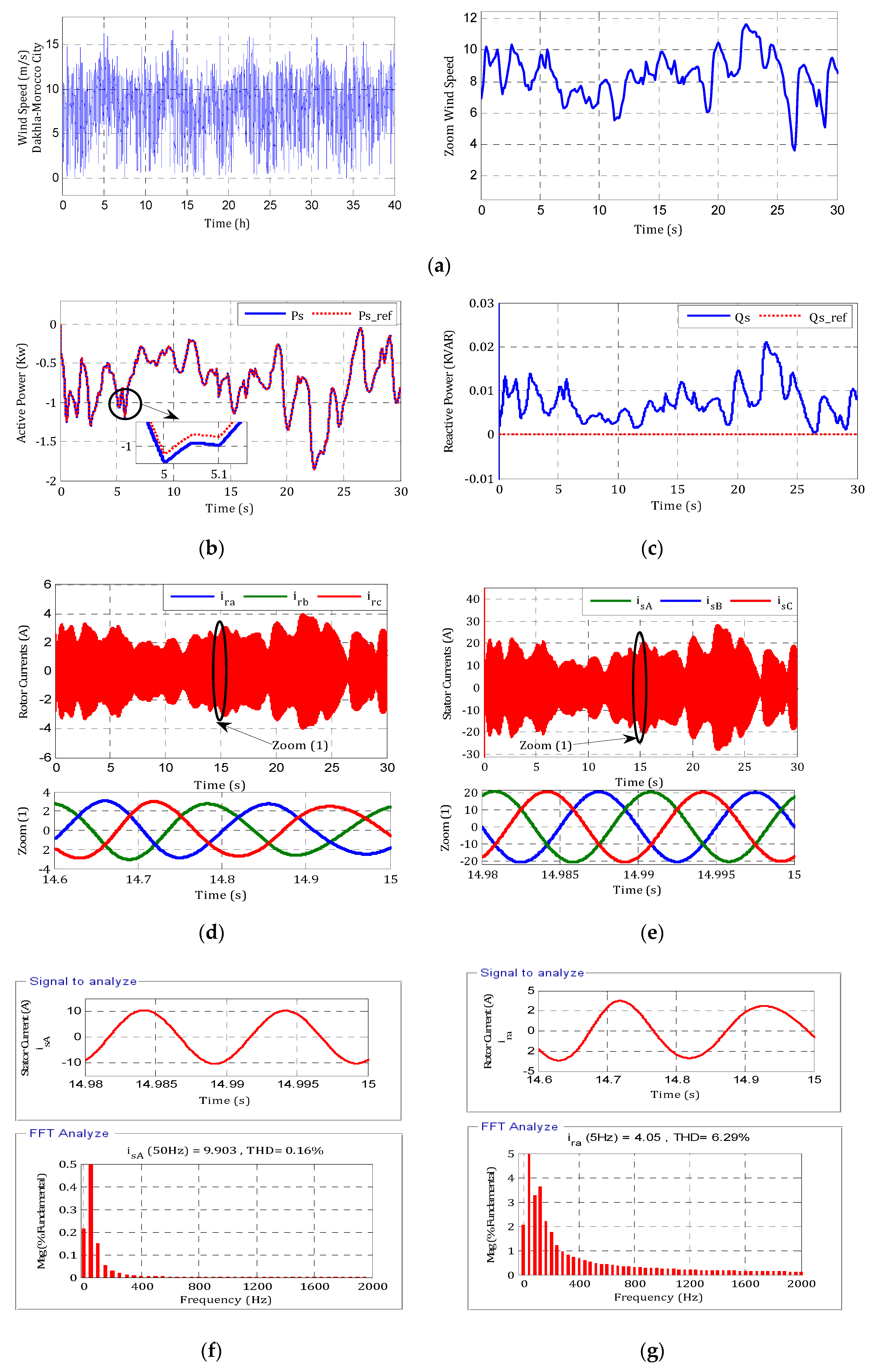
The wind profile used for these tests is variable (Figure 6a). It is a wind profile that corresponds to that of Dakhla City, Morocco.
The results obtained show that (Figure 6):
  • The active and reactive power perfectly follows the generated setpoints, the unit power factor obtained after the end of its transient regime.
  • The quality of the energy is much improved; the evolution of the currents is indeed sinusoidal, with a frequency of 50 Hz.
  • The harmonic distortion is significant (6.29%) for the current rotor and only 0.16% for the stator current.

6.3. Robustness Test

To check the robustness of this control, adjustments are made to the internal parameters of the DFIG model used. The following graphs illustrate the dynamic behavior of the machine for several tests of robustness based on parameter variations [21]:
From these results, we notice that (Figure 7):
  • Variations in stator (Rs) and rotor (Rr) resistances result in a small increase in response time, with almost zero static error and less oscillation.
  • The fluctuations of the rotor and stator inductances (Lr) and (Ls) show the same response time in the beginning, with low sensitivity in the dynamics of the reference, which always maintains the decoupling between the active and reactive powers.

6.4. Hardware Test

The following figures show the experimental results of the switching signals (Sa, Sb, Sc) applied to the inverter obtained by the oscilloscope to the output of the FPGA board Nexys 2 (Figure 8).

6.5. Comparison Study

Table 1 shows a comparison between the proposed technique and some recently published control strategies studied.
A comparison of results between the developed control and other recent studies is shown in Table 1. Although the error is minimized compared to [10,11,12], the biggest advantage of this control is the significant response time, and the overshoot was reduced. Comparing the power ripple of this study with [10,11,12], it is remarkable that the ripple has been decreased in a significant way for the controls proposed.
In summary, the adaptive Backstepping control offers good performances (reduced response time, good tracking of references), with a dynamic error of εd = 1.05% and a static error of εs = 0.067%.

7. Conclusions

The combination of adaptive Backstepping control and flux orientation confirmed the good attributes of performance and robustness in this work. It has the advantage of being robust with the machine’s parametric variation and good tracking of the references. The adaptive Backstepping control approach based on the Lyapunov theory is established in detail. After evaluating the system control in a Matlab/Simulink environment with the Xilinx “SYSTEM GENERATOR,” the FPGA Nexys 2 board was implemented. The results show that the proposed control strategy provides good performance (lower response time, good tracking of references, and lower errors). In addition, it ensures robustness against variations in the wind profile and the machine parameters are well ensured, thanks to this control algorithm. The experimental hardware co-simulation demonstrates that the proposed control strategy provides good static and dynamic performances of the system. Therefore, the effectiveness of this control has been validated. The analysis of the harmonic distortion results (6.29% at the rotor current and 0.16% at the stator current) guarantee connecting the DFIG machine to the grid for injecting the energy in the electrical grid.

Author Contributions

Conceptualization, M.T.; methodology, M.K. and M.T.; software, S.M.; validation, M.T. and B.B.; formal analysis, M.T. and N.Z.; investigation, M.T.; resources, M.T.; data curation, M.T.; writing—original draft preparation, M.T.; writing—review and editing, M.B., E.H.A., S.M. and M.K.; visualization, M.K.; supervision, E.H.A., S.M., B.B. and M.M.; project administration, B.B.; funding acquisition, E.H.A. All authors have read and agreed to the published version of the manuscript.

Funding

This work is supported by Taif University Researchers Supporting Project Number (TURSP-2020/292), Taif University, Taif, Saudi Arabia.

Institutional Review Board Statement

Not applicable.

Informed Consent Statement

Not applicable.

Data Availability Statement

Not applicable.

Acknowledgments

The authors would like to acknowledge the Taif University Researchers Supporting project (no. TURSP-2020/292), Taif University, Taif, Saudi Arabia.

Conflicts of Interest

The authors declare no conflict of interest.

Appendix A

Table A1. DFIG parameters.
SymbolQuantityValues
PsStator power 1.5 KW
pPole number2
RsStator resistance4.85 Ω
RrRotor resistance3.805 Ω
LsStator inductance274 mH
LrRotor inductance258 mH
TemElectromagnetic torque32 Nm
Table A2. Wind turbine parameters.
SymbolQuantityValues
RRadius of the turbine blade20 m
JTurbine and generator moment1000 N.m
ρSpecific density of air1.22 kg/m3
λoptTip–speed ratio8
CpOptimal power coefficient0.45

References

  1. Kazemia, M.V.; Moradib, M.; Kazemi, R.V. Minimization of powers ripple of direct power controlled DFIG by fuzzy controller and improved discrete space vector modulation. Electr. Power Syst. Res. 2012, 89, 23–30. [Google Scholar] [CrossRef]
  2. Yung-Tsai, W.; Yuan-Yih, H. Reactive power control strategy for a wind farm with DFIG. Renew. Energy 2016, 94, 383–390. [Google Scholar]
  3. Yao, J.; Li, H.; Chen, Z.; Xia, X.; Chen, X.; Li, Q.; Liao, Y. Operation of Wind Turbine-Driven DFIG Systems Under Distorted Grid Voltage Conditions: Analysis and Experimental Validations. IEEE Trans. Power Electr. 2013, 28, 3167–3181. [Google Scholar]
  4. Ebrahimkhani, S. Robust fractional order sliding mode control of doubly-fed induction generator (DFIG)-based wind turbines. ISA Trans. 2016, 63, 343–354. [Google Scholar] [CrossRef] [PubMed]
  5. Ademi, S.; Jovanovic, M. High-efficiency control of brushless doubly-fed machines for wind turbines and pump drives. Energy Conv. Manag. 2014, 81, 120–132. [Google Scholar] [CrossRef]
  6. Kaloi, G.S.; Wanga, J.; Baloch, M.H. Active and reactive power control of the doubly fed induction generator based on wind energy conversion system. Energy Rep. 2016, 2, 194–200. [Google Scholar] [CrossRef] [Green Version]
  7. Bouderbala, M.; Bossoufi, B.; Deblecker, O.; Alami Aroussi, H.; Taoussi, M.; Lagrioui, A.; Motahhir, S.; Masud, M.; Alraddady, F.A. Experimental Validation of Predictive Current Control for DFIG: FPGA Implementation. Electronics 2021, 10, 2670. [Google Scholar] [CrossRef]
  8. Aroussi, H.A.; Ziani, E.; Bouderbala, M.; Bossoufi, B. Enhancement of the direct power control applied to DFIG-WECS. Int. J. Electr. Comput. Eng. 2020, 10, 35. [Google Scholar] [CrossRef]
  9. Bossoufi, B.; Karim, M.; Lagrioui, A.; Taoussi, M.; EL Hafyani, M.L. Backstepping Adaptive Control of DFIG-Generators for Variable-Speed Wind Turbines. Int. J. Comput. Technol. 2014, 12, 3719–3733. [Google Scholar] [CrossRef]
  10. Taoussi, M.; Karim, M.; Bossoufi, B.; Hammoumi, D.; Lagrioui, A. Speed Backstepping control of the doubly-fed induction machine drive. J. Appl. Inf. Technol. 2015, 74, 189–199. [Google Scholar]
  11. Saady, I.; Bossoufi, B.; Karim, M.; Motahhir, S.; Adouairi, M.S.; Majout, B.; Lamnadi, M.; Masud, M.; Al-Amri, J.F. Optimisation for a photovoltaic pumping system using indirect Field Oriented Control of Induction Motor. Electronics 2021, 10, 3076. [Google Scholar] [CrossRef]
  12. Zhou, D.; Blaabjerg, F.; Lau, M.; Tonnes, M. Optimized Reactive Power Flux of DFIG Power Converters for Better Reliability Performance Considering Grid Codes. IEEE Trans. Ind. Electr. 2015, 62, 1552–1562. [Google Scholar] [CrossRef]
  13. Alami Aroussi, H.; Ziani, E.M.; Bossoufi, B. Robust control of a power wind system based on the double fed induction generator (DFIG). J. Autom. Syst. Eng. JASE 2015, 9, 156–166. [Google Scholar]
  14. Taoussi, M.; Karim, M.; Bossoufi, B.; Lagrioui, A.; El Mahfoud, M. The Fuzzy Control for Rotor Flux Orientation of the doubly-fed asynchronous generator Drive. Int. J. Computers Technol. 2014, 13, 4707–4722. [Google Scholar] [CrossRef]
  15. Bossoufi, B.; Karim, M.; Taoussi, M.; Aroussi, H.A.; Bouderbala, M.; Deblecker, O. Rooted Tree Optimization for Backstepping Power Control of DFIG Wind Turbine: dSPACE Implementation. IEEE Access 2021, 9, 26512–26522. [Google Scholar] [CrossRef]
  16. Bossoufi, B.; Karim, M.; Lagrioui, A.; Taoussi, M. FPGA-Based Implementation nonlinear Backstepping control of a PMSM Drive. IJPEDS Int. J. Power Electr. Drive Syst. 2014, 4, 12–23. [Google Scholar]
  17. Hu, J.; Yuan, X. VSC-based direct torque and reactive power control of doubly fed induction generator. Renew. Energy 2012, 40, 13–23. [Google Scholar] [CrossRef]
  18. Bossoufi, B.; Taoussi, M.; Alami Aroussi, H.; Bouderbala, M.; Motahhir, S.; Camara, M.B. DSPACE-Based Implementation for Observer Backstepping Power Control of DFIG Wind Turbine. IET Electr. Power Appl. 2020, 14, 2395–2403. [Google Scholar] [CrossRef]
  19. Mellit, A.; Mekki, H.; Messai, A.; Kalogirou, S.A. FPGA-based implementation of intelligent predictor for global solar irradiation, Part I: Theory and simulation. Expert Syst. Appl. 2011, 38, 2668–2685. [Google Scholar] [CrossRef]
  20. Bossoufi, B.; Karim, M.; Lagrioui, A.; Taoussi, M.; Derouich, A. Observer Backstepping control of DFIG-Generators for Wind Turbines Variable-Speed: FPGA-Based Implementation. Renew. Energy J. 2015, 81, 903–917. [Google Scholar] [CrossRef]
  21. Orosz, T.; Rassõlkin, A.; Kallaste, A.; Arsénio, P.; Pánek, D.; Kaska, J.; Karban, P. Robust Design Optimization and Emerging Technologies for Electrical Machines: Challenges and Open Problems. Appl. Sci. 2020, 10, 6653. [Google Scholar] [CrossRef]
Figure 1. Implementation steps in the FPGA target.
Electronics 10 03154 g001
Figure 2. Functional model hybrid control.
Electronics 10 03154 g002
Figure 3. Real-time implementation of hybrid control in an FPGA Nexys 2 board.
Electronics 10 03154 g003
Figure 4. Block diagram of implementation of a DFIG in an FPGA Nexys 2 board.
Electronics 10 03154 g004
Figure 5. Co-simulation experimental results with a wind speed of 12 m/s: (a) active power; (b) reactive power; (c) rotor current; (d) stator current; (e) THD rotor current; and (f) THD stator current.
Electronics 10 03154 g005
Figure 6. Co-simulation experimental results with a real wind profile: (a) wind speed; (b) active power; (c) reactive power; (d) rotor current; (e) stator current; (f) THD rotor current; (g) THD stator current.
Electronics 10 03154 g006
Figure 7. Co-simulation experimental robustness results with a wind speed of 12 m/s when varying (a) rotor resistor, (b) stator resistor, (c) rotor inductance, and (d) stator inductance.
Electronics 10 03154 g007
Figure 8. Experimental results of the switching signals obtained by the oscilloscope.
Electronics 10 03154 g008
Table 1. Comparison between our proposal and some control strategy published recently.
PublicationTechniquePerformancesRobustness
Response Time Error Ɛs (%)Overshot (%)Power Ripple
[9]DTC-classical---0.32%5%---Moderate
DTC-GA-based PI ---0.12%1%---Moderate
[10]High-order sliding mode 130 ms0.2%0%±17 wHigh
Fuzzy siding mode150 ms0.14%0%±15 wHigh
[11]DPC 200 ms---0%±19 wModerate
[12]Fuzzy-Pi 230 ms0.15%5%±23 wLow
Proposal techniqueHybrid control170 ms0.12%0%±5 wHigh
Publisher’s Note: MDPI stays neutral with regard to jurisdictional claims in published maps and institutional affiliations.