Article

Architecture Design for Feature Extraction and Template Matching in a Real-Time Iris Recognition System

1
Electrical and Computer Engineering Department, U.S. Naval Academy, Annapolis, MD 21402, USA
2
Weapons, Robotics, and Control Engineering Department, U.S. Naval Academy, Annapolis, MD 21402, USA
*
Author to whom correspondence should be addressed.
Electronics 2021, 10(3), 241; https://doi.org/10.3390/electronics10030241
Submission received: 23 December 2020 / Revised: 12 January 2021 / Accepted: 19 January 2021 / Published: 21 January 2021
(This article belongs to the Section Computer Science & Engineering)

Abstract

:
Real-time support for an iris recognition algorithm is a considerable challenge for a portable system that is commonly used in the field. In this paper, an efficient parallel and pipeline architecture design for the feature extraction and template matching processes in the Ridge Energy Direction (RED) algorithm for iris recognition is presented. Several techniques used in the proposed architecture design to reduce the computational complexity while supporting a high performance capability include (i) a circle approximation method for the iris unwrapping process, (ii) a parallel design with an on-chip buffer for 2D convolution in the feature extraction process, and (iii) an approximation method for log2 and inverse-log2 conversion in the template matching process. Performance analysis shows that the proposed architecture achieves a speedup of 881 times compared to the conventional method. The proposed design can be integrated with an embedded microprocessor to realize a complete system-on-chip solution for a portable iris recognition system.

1. Introduction

Biometrics is the quantitative measurement of human characteristics typically used for security purposes, such as authentication and personal identification [1,2]. The human iris can be used to identify a person through means of an iris recognition system [3]. Iris recognition is one of the best biometric-based authentication systems used today due to its low error rates [4]. As a result, iris recognition can be used not only in security systems, but for other purposes [5]. For example, in the field of consumer electronics, the trend in recent years indicates a greater use of biometric applications in handheld devices for authentication and security purposes [6]. Using an iris recognition method to authenticate a user is much more secure than using a password for controlled access. The reliability and accuracy of these algorithms can be further improved by combining multiple biometric features, such as the face, left iris, right iris, fingerprint, etc. [7].
The algorithm that will be used for this research is the Ridge Energy Direction (RED) algorithm [8]. This algorithm processes images captured using near-infrared illumination (NIR), by detecting the boundaries of the iris, unwrapping the iris using polar-to-rectangular conversion, processing it to extract features, and matching binary templates using the fractional Hamming distance equation. This algorithm has been proven to be a robust method that is able to recognize images with a wide range of features. To support in-the-field users, this algorithm needs to be able to perform in real-time in resource-constrained portable devices. The main goal of this work is to incorporate the RED algorithm into resource-constrained embedded devices to support the real-time processing capability. In order to achieve the research goal in this work, the available resources must be fully exploited to support massive parallel processing paths for the computationally intensive operations in the algorithm.
In recent years, researchers have used Graphic Processing Units (GPUs) to apply a form of parallel processing capability in the fields of image processing and artificial intelligence applications [9,10]. Field Programmable Gate Array (FPGA) devices have also been used as platforms for rapidly realizing hardware accelerators for computationally-intensive applications. These FPGA platforms with built-in digital signal processing (DSP) units, a large number of embedded memory blocks and registers, and high-speed memory and storage interfaces have provided a suitable solution to facilitate a complete system-on-chip (SoC) design. A complete SoC system can significantly reduce the memory bandwidth requirement in a real-time iris recognition application. Many researchers have utilized the capabilities of FPGA technology to implement real-time systems for computationally- and data-intensive image processing applications [11,12]. In recent years, the use of FPGA devices to accelerate artificial neural networks with an embedded processor to support the real-time capability in the area of computer vision and image processing has increased considerably [13,14]. An FPGA device is used as an implementation platform in this work.
This paper presents a novel architecture design and implementation for the feature extraction and template matching processes of an iris recognition system. Specifically, efficient iris unwrapping and convolution filtering processes are proposed to aggressively utilize embedded resources in the feature extraction step. For the RED algorithm, the detected iris is unwrapped into a rectangular image using the trigonometric polar coordinate transform. This concept of iris unwrapping is commonly used in many iris recognition systems [15,16,17]. In order to reduce the processing time of the iris unwrapping operation, the Bresenham circle algorithm (BCA) is used to generate pixel locations in an iris image [18,19,20]. In the template matching module, a design in log-domain in considered to eliminate division operations. The main contributions presented in this work can be summarized as follows:
  • A novel architecture design that uses BCA in the iris unwrapping process is presented. This approach is utilized to replace trigonometric operations that are widely used in conventional approaches with simple add, subtract, and shift operations;
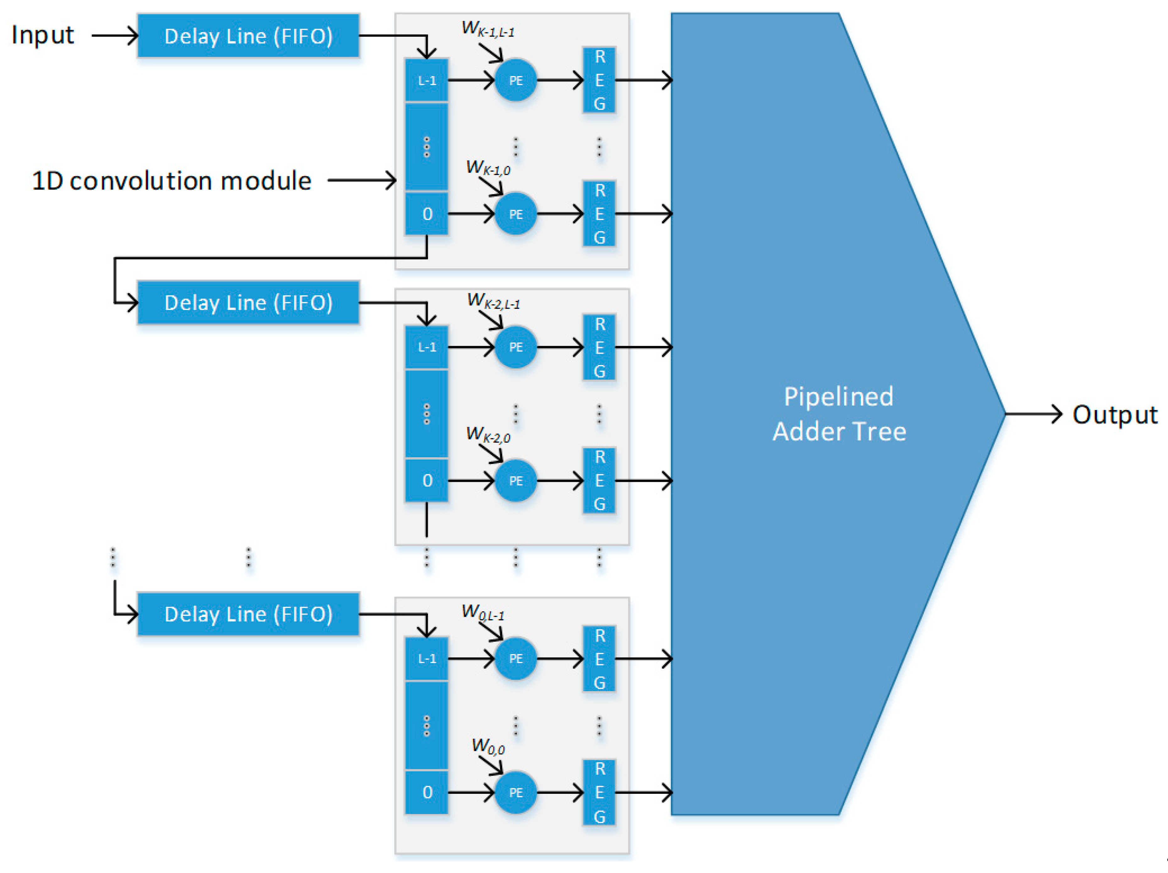
  • A parallel architecture design for the two-dimensional (2D) convolution process in feature extraction is presented. This design uses a full-window buffering scheme to effectively utilize on-chip memory blocks for delay buffers, in order to reduce the memory bandwidth;
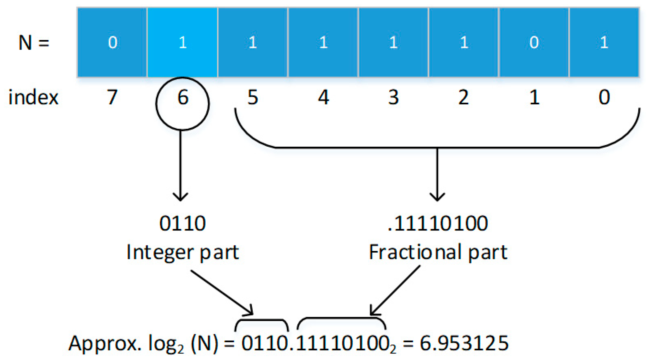
  • Approximation techniques for reducing complex operations in the architecture design for the template matching process are presented. The proposed approximation techniques transform division operations into log-based subtraction operations to reduce iterative computational processes.
The proposed parallel-pipeline architecture design for feature extraction and template matching has been evaluated with a cost-effective FPGA device. The simulation results show that the proposed architecture design can support the real-time processing requirement. With an FPGA as the main integration platform, the proposed design has the capability to smoothly interface with an embedded processor and other peripherals to support real-time iris recognition in a portable platform.
This paper is organized as follows. A brief review of the RED algorithm is provided in Section 2, while Section 3 discusses the proposed design of a high-performance architecture for feature extraction and template matching. Implementation results and discussions are presented in Section 4. Finally, conclusions and potential future work are provided in Section 5.

2. Overview of an Iris Recognition Algorithm

The main steps of the iris recognition system using the RED algorithm are as follows: Iris boundary segmentation, where the system detects and extracts the iris from the image; feature extraction, where the system converts the extracted iris into a binary template; and template matching, where the system compares the current template with other existing templates in the database to make a recognition decision. An overview block diagram of these steps is shown in Figure 1.

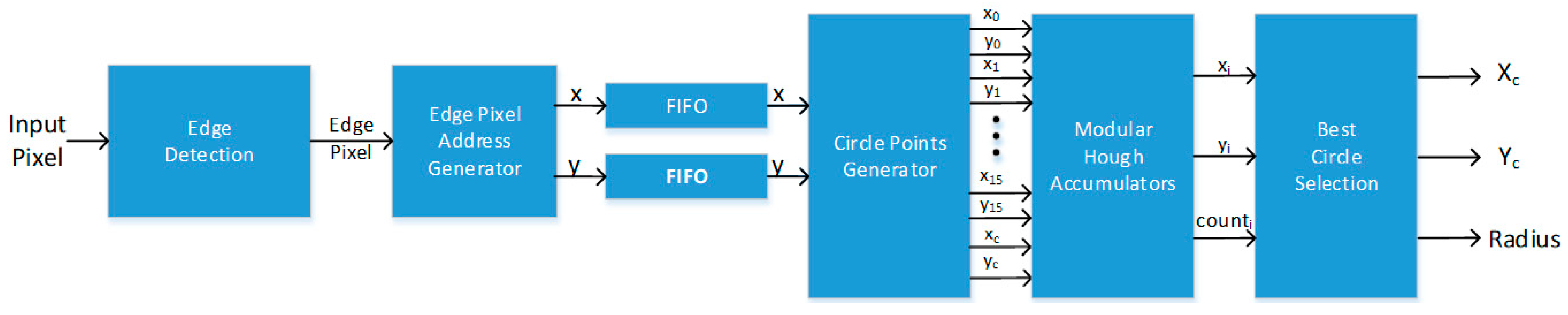
2.1. Iris Boundary Detection

Iris detection is the process of determining the location of the iris in the image. There are numerous methods that can be used to perform iris boundary detection and many of these techniques require some sort of preprocessing step. Pre-processing methods such as noise filtering processes are important for extracting salient information [21,22,23]. The RED algorithm uses a noise filtering step with a Gaussian kernel to extract edge pixels in the iris images. In this iris boundary detection step, the Hough transform is used to detect the limbic and pupil boundaries of the iris in an edge image. This step has been presented in a previous paper and the results have demonstrated that a great speedup can be achieved by the FPGA-based design, while maintaining a high detection rate of over 92% [6]. The iris boundary parameters (i.e., the center coordinate and the pupil and limbic radii of the iris) are the output values of this segmentation module and will be used by subsequent modules as the model parameters in the iris unwrapping process.

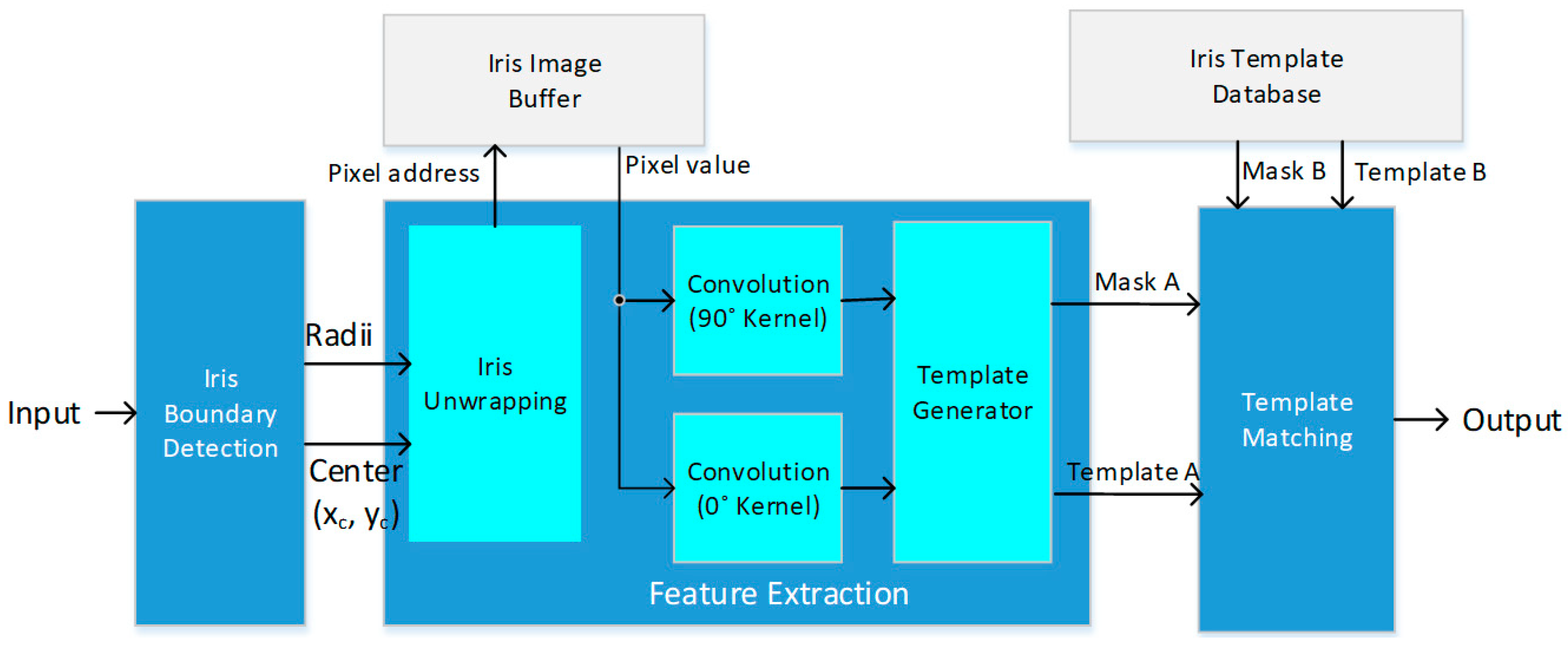
2.2. Feature Extraction

Feature extraction is the conversion of the segmented iris image into a binary template or machine code that represents the distinctive information in the iris. In the RED algorithm, this step includes unwrapping the segmented iris image into a rectangular matrix, and applying two-dimensional convolution using two directional filters (vertical or horizontal) to produce two outputs for every pixel location. The output with the highest return value indicates the presence of a strong ridge and is encoded with one bit to indicate the ridge direction (e.g., 0 for a vertical ridge, and 1 for a horizontal ridge). This process will create a template of binary data, which will be used in the template matching step to identify individuals. At the same time, an image could contain eyelashes and other noise that could be falsely identified as part of the iris. To account for this, a mask is created—of the same size as the template—containing a 1 to indicate a valid iris pixel and a 0 to indicate noise.

2.3. Template Matching

Template matching is the process in which the iris recognition system takes the created binary template and compares it to each template stored in its database to determine whether a match is found. To implement this step, the RED algorithm uses the fractional Hamming distance (HD) equation to measure how close the two templates (i.e., template A and template B) are to each other, given by Equation (1).
H D   =     ( template   A     template   B )     ( mask   A     mask   B )     mask   A     mask   B  
The operator is the binary exclusive-or operation. This is used to detect disagreement between the bits from the two templates which represent the ridge detection of the corresponding pixels. The symbol ⋅ represents the binary AND function, which is used in the numerator to discount noise pixels in the templates, and in the denominator to dispel any non-iris areas that could affect the accuracy of the calculation. The   operator is the summation operator, so that the fractional Hamming distance is the fraction of iris pixels that do not match for the two templates, discounting noise pixels in each template.

3. Architecture Design

In this work, the hierarchical approach is considered in the architecture design, where the overall architecture is partitioned into smaller components. These components are tested and verified separately before all the components are integrated into a single system. The parallel and pipeline architecture design methodologies are emphasized to achieve a higher performance. A general block diagram for the complete design of the iris recognition system is shown in Figure 2.
The boundary parameters (i.e., Center (xc, yc) and Radii) from the Iris Boundary Detection module, along with the input image buffer, are treated as inputs for the Feature Extraction module. The pixels of the iris are sequentially unwrapped from the input image using the Bresenham circle algorithm. These unwrapped pixels are then convolved using a single kernel matrix, but at two different positions, creating two outputs for each unwrapped pixel. These outputs are compared and the bit value of the template is determined based on their difference. Accordingly, the template matching module compares the incoming binary template to stored templates in a database to determine whether a match has been detected.

3.1. Iris Boudary Detection Module

The architecture design for this module is based on a modular approach to implement the circular Hough Transform, in order to reduce the memory requirement. The reduction in the memory requirement allows the entire Hough transform buffer space to be implemented with the on-chip memory of an FPGA device. The design of this proposed architecture has been presented in a previous work [6]. This implementation significantly reduces the amount of access to the external memory chip and consequently increases the system performance by a large margin. A general block diagram of iris boundary detection is shown in Figure 3. In this paper, the outputs of the iris detection module (i.e., Center (xc, yc) and Radii) are assumed to be available as inputs for the feature extraction module.

3.2. Feature Extraction Module

The two main operations in this module are the iris unwrapping and windowed filtering, as shown in++ Figure 2. To accomplish the iris unwrapping process, two techniques, including polar conversion and the Bresenham circle algorithm (BCA), are considered. To speed up the convolution filtering process, a parallel convolution design is implemented. The design discussions for these two operations are presented next.

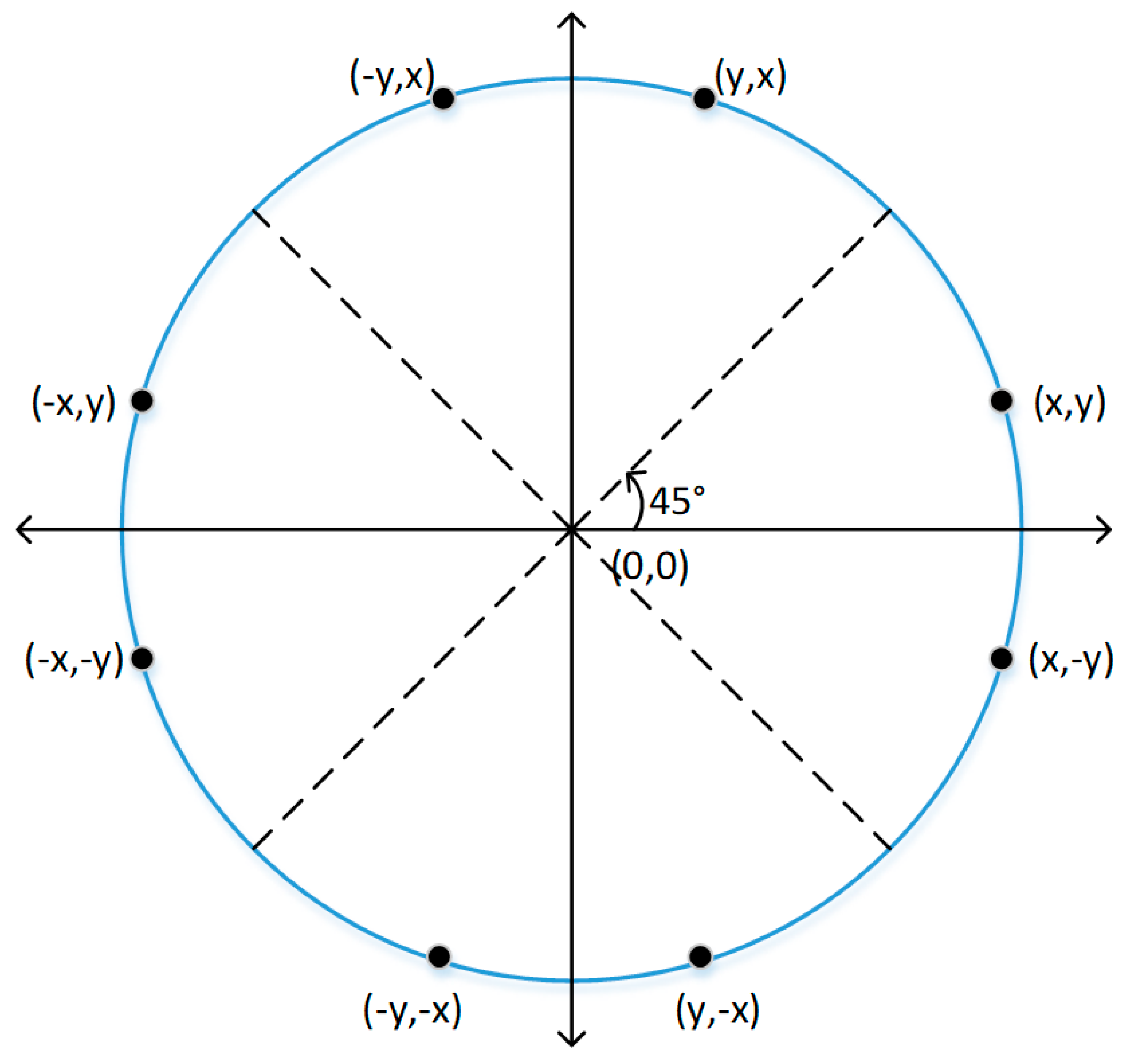
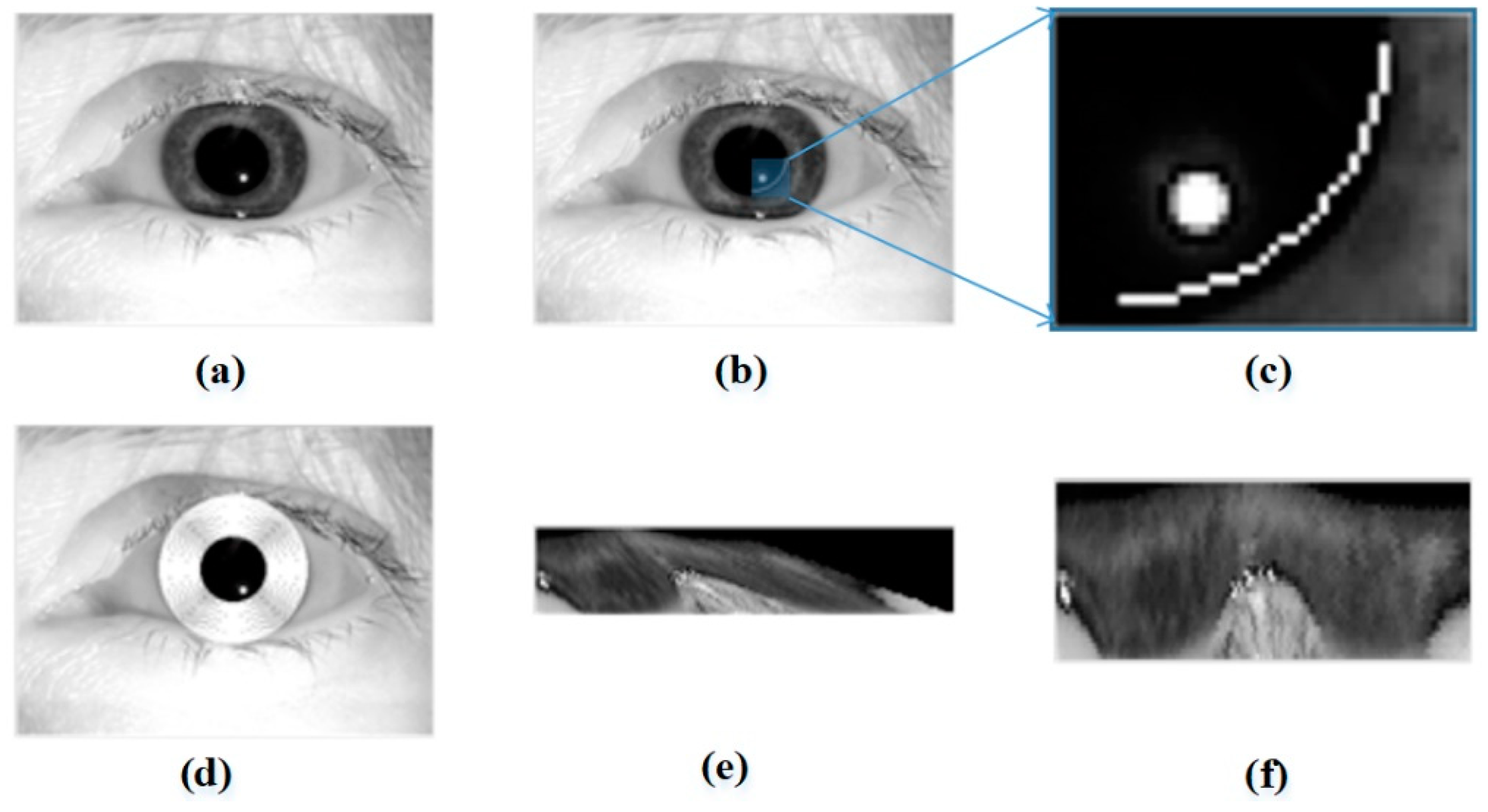
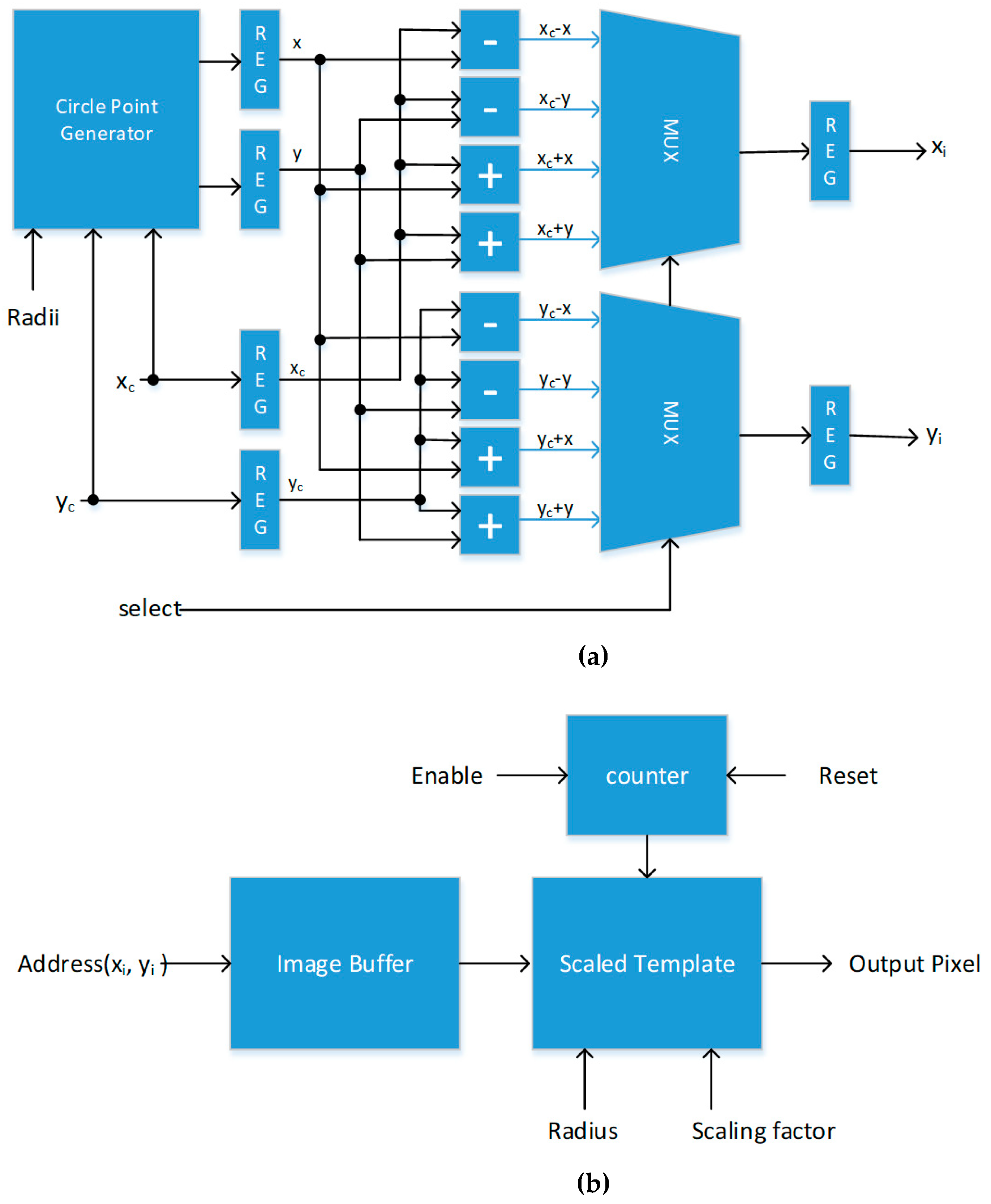
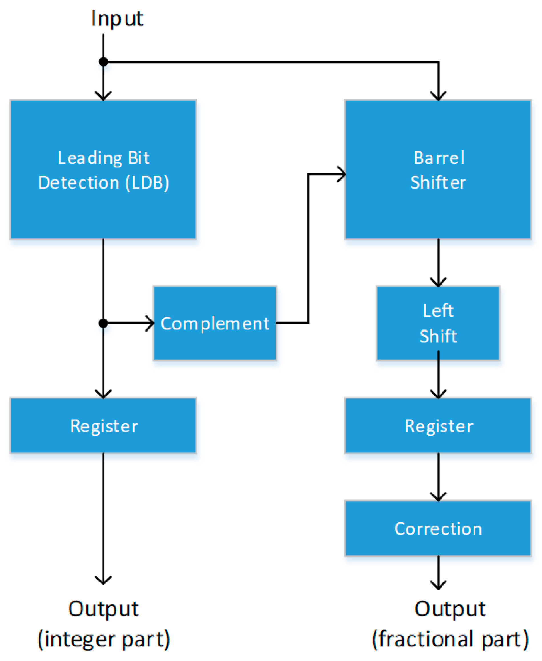
3.2.1. Iris Unwrapping

The iris unwrapping process labels the pixels of the segmented iris with polar coordinates. These coordinates are then converted into rectangular coordinates, which become the addresses of the pixels in the segmented iris. The processing time required to unwrap a single iris image by means of polar conversion is proportional to the pre-determined size of the binary template. As a result, the advantage of this technique is that the processing time is the same for every image. However, the polar conversion technique usually has limitations due to its computational complexity and high memory requirements if using cosine and sine lookup tables [24].
To reduce the memory and computational requirements, the BCA is considered in this work to generate circle points which are used to unwrap an iris image. Initially proposed by Wright, the BCA was parallelized to increase the throughput of the computer graphic system [19]. In an iris image, concentric circles can be used to map all the pixels within the iris into a standard iris template. Accordingly, the BCA is used to create all the concentric circles within an iris image in this work. The x and y coordinates for every point created in a circle can be used as the address for the desired pixel value located in the input iris image. Once the center of the circle is determined, pixel locations in a circle with a specified radius within the segmented iris image can be determined. The radius of the next circle is incremented until the radius limit (or template size) is met.
The BCA is also chosen over the polar conversion technique due to the speedup it provides compared to the polar conversion technique given the desired size of the binary template in the RED algorithm. The size of the binary template used in the research was 92 rows by 180 columns. If the polar conversion technique is implemented, the processing time is determined by the size of the desired template. For the polar conversion technique, a pixel location (x, y) with respect to radius r and center (xc, yc) is determined as
x = x c + [ r × c o s ( θ ) ] ,
y = y c + [ r × s i n ( θ ) ] .
With 16,560 bits (92 × 180) inside a desired binary template, the polar conversion technique would take at least 16,560 iterations to unwrap an iris image. Each iteration using the polar conversion technique would require two trigonometric operations, along with two multiplications and two additions. With the BCA method, the processing time is the summation of the number of pixels on the circumferences of all concentric circles within the iris image. Figure 4 will be used for an illustration of how the BCA method can be used to quickly determine the next pixel location. Each pixel location in a circle circumference is determined by the location of the adjacent neighbor. For example, assume that the current pixel location is (x, y) in Figure 4, so the next location to the right of this pixel can either be pixel ((x + 1, y) or pixel (x + 1, y − 1). The pixel errors between the two potential locations and the circle point on the circumference are used to determine the next pixel location. Specifically, the pixel location with the smaller error will be selected. Therefore, for the illustration shown in Figure 4, the pixel (x + 1, y − 1) is selected. The same process is repeated for the next point on the circle. While the conventional trigonometric-based method requires a significant number of multiplications and additions, the proposed BCA method uses simpler operations, such as addition, subtraction, and bit shifting operations.
To calculate the circle coordinates, the BCA only needs the x and y center coordinates of the desired circle and its radius. The BCA method uses the x and y center coordinates of the limbic circle (outer iris boundary) to create the next point of the circle according to the algorithm described in Algorithm 1. Note that multiplications in Algorithm 1 can be readily achieved by the left shift operation. This means that the circle points can be computed with simple operations, such as addition, subtraction, and bit shifting operations.
Algorithm 1: Bresenham Circle Point Generation.
  • x = 0
  • y = radius
  • p = 6 − 2*radius
  • while x > y
  •   x = x + 1
  •   if p < 0
  •    p = p + 4 x + 6
  •   else
  •    y = y − 1
  •    p = p + 4(x − y) + 10
  •   end if
  • end while
In Algorithm 1, the x and y values are the coordinates of the circle points. p is the value for the direction error that is used to determine the next value of y. The direction error essentially indicates how close the current coordinate is to the actual circle perimeter. The value of y is adjusted based on the direction error. Due to the circle’s symmetry, only circle points in the first 45° region of a circle are computed based on Algorithm 1. The circle points in the other regions of the circle can be quickly computed with simple processing units. An illustration of the circle’s symmetry is shown in Figure 5. For example, given one coordinate (x, y), the other seven coordinates can be determined by rearranging the x and y coordinates and their negative values as shown in Figure 5.
For each circle, its radius value can be used to calculate the approximate number of pixels that make up said circle, no matter where the x and y center coordinates are in the image. This number is constant for every circle with an equal radius. This is useful for scaling the data in the columns of each row in the rectangular matrix, which is required to maintain the standard template size.
The number of concentric circles created to unwrap the iris is the difference between the limbic and pupil radii, ΔR. This takes up to (92 − ΔR) × 180 less clock cycles than the polar conversion technique in the iris unwrapping operation. The process starts by creating the (xp, yp) coordinates from the input parameters, one by one. The first coordinate starts at the edge of one octant of the circle and moves toward the edge of the octant and around the pupil, as can be seen in Figure 6b,c. Note that, for illustration purposes, only quadrant symmetry is considered in this figure.
Each point in the circle is the address of the desired pixel in the input image. Once calculated, the pixel is read from the input image buffer and transferred to the windowed filtering step. Once the circle is completed, the next circle starts in the same way as the previous one, but with a radius increased by one pixel. The radius keeps increasing until it reaches the radius value of the limbic circle, as shown in Figure 6d. Due to the uneven circumferences of the concentric circles, the number of columns filled with a value in each row will be unequal, as shown in Figure 6e. To normalize these circles for a standard template size, the values in each row are scaled to fill all 180 columns in the template. The result of this scaling operation is shown in Figure 6f. The number of pixels that the algorithm uses to create each circle with a corresponding radius is known. The radius is multiplied by a pre-determined scale factor which approximated the circumference of the circle. This number is then multiplied by the reciprocal of 180 to scale the circle to 180 columns in the binary template.
The architecture design for the circle point generator is shown in Figure 7. The parameters that are received from the iris detection module are the x and y center coordinates of the limbic circle, including the pupil and limbic radii. These values are stored in registers after the first clock cycle, in order to be used throughout the entire unwrapping process. Assuming that the pupil and limbic circles are concentric, only the central coordinates of the limbic circle are stored. Each internal parameter value is stored in a corresponding register and updated with a new value for each clock cycle.
Each of the circle points is selected via multiplexers and then routed to an image buffer, in order to retrieve the pixel values. Once the (xp, yp) coordinates of the next point in the circle have been calculated, those values are used to locate the desired pixel from the input image stored in an embedded random access memory (RAM) module. The desired pixel value is then transferred to a scaling block, in order to stream the pixels in a template to the windowed filtering block (two-dimensional (2D) convolution).
To scale the data into every column of each row, the number of pixels that make up the current circle must be multiplied by the scale factor. Regardless of the number of points in each unwrapped circle, all unwrapped pixels must be stored temporarily. A 2-port RAM block with a length of 180 is used internally to store the scaled template. If the ratio is less than 1, each pixel is temporarily stored and read as the scale variable value is applied and pixel locations are generated. On the other hand, if the ratio is greater than 1, the number of points in the circle have to be scaled down to fit into 180 columns. The 2-port RAM provides the flexibility needed to execute this process by being able to write to one address while simultaneously reading from another.

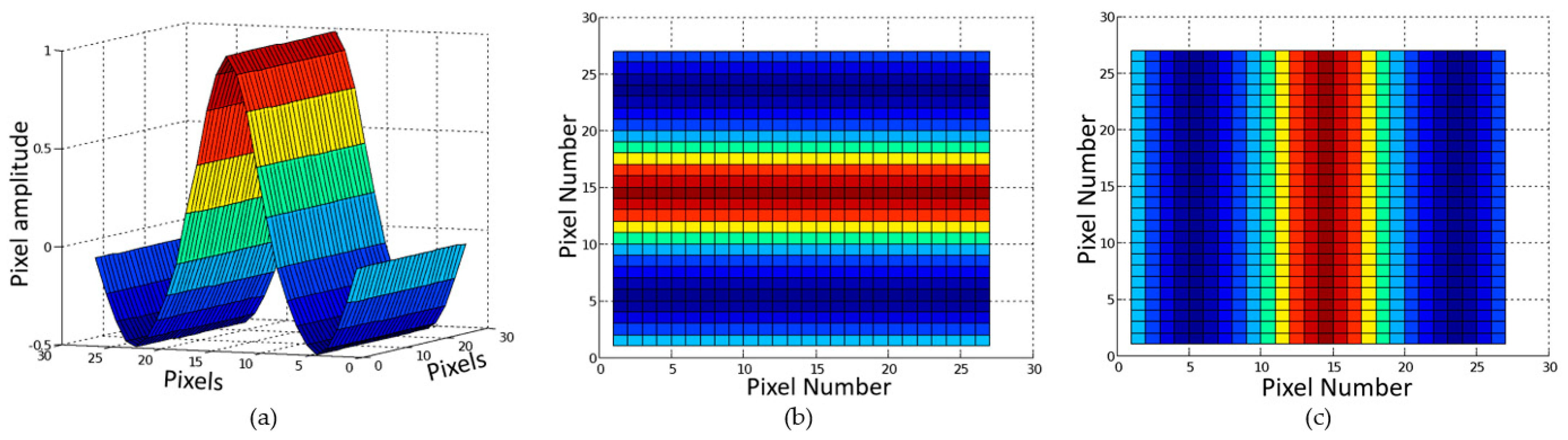
3.2.2. Window-Based Filtering

The next step in the algorithm is to perform the filtering process, which compresses the unwrapped iris image into binary data. Pixel values inside the input image are extracted using the BCA and the directional filter with corresponding values from an optimized cosine kernel matrix are then applied. This process is carried out with 2D convolution (or window-based filtering/operation), which requires a large number of repetitive computational operations on a fixed window of neighboring pixels centered on a reference pixel (pixel under consideration). To compute the pixel value of an output pixel, each reference pixel in the window of the input image is extracted and multiplied with the corresponding weight in the kernel mask and the results are summed to produce the value of the output pixel. Due to the repetitive nature in the applications, these window-based operations present a high degree of processing parallelism that can be exploited to achieve a higher performance.
This execution occurs with two kernels in horizontal and vertical directions of 0° and 90°, respectively. In other words, the convolution process is executed twice, with the kernels in different directions. Accordingly, two values are outputted, corresponding to each kernel, and the two outputs are compared to determine which is larger; depending on the decision, a binary 1 or 0 will be inserted into the binary template.
The kernel used in this research can be described as a normalized cosine wave function with boundaries of (       3 π 2 < x < 3 π 2   ) at an amplitude of   (       1 2 < y < 1   ) in a 27 by 27 matrix. The function is symmetrical about the y-axis, producing a zero when all values are summed. The cosine function was first calculated in MATLAB, as shown in Figure 8a.
Previous research has determined that a 27 by 27 matrix is the optimal size for the kernel in the convolution process [8]. Furthermore, in this research, each row of the kernel at 0° is equivalent, with the same values from the cosine function, and similarly with each column for the kernel at 90°, as shown in Figure 8b,c.
Before convolving the first 27 rows of the unwrapped iris, the design must wait for those first 27 rows to be unwrapped. After the initial convolution latency, the kernel slides to the next position with a single increment to consider the next 27 columns while staying within the initial 27 rows. Once the kernel reaches the end of the 180 columns of a row of the unwrapped iris, it will move down by one row and repeat the sliding process across the matrix again. This procedure will continue until the kernel reaches the last row in the unwrapped iris image. This window sliding process requires an efficient on-chip buffering mechanism to support the parallel operation. A full-window buffering scheme is considered for design of the 2D convolution module.
For 2D convolution with a K × L kernel mask, (K × L) multiplications, (K × L-1) additions, and (K × L) memory accesses to pixels in the reference window are required for one output pixel. In order to take advantage of the inherent parallelism in the operations, access to the reference pixels must be achieved simultaneously. Generally, 2D convolution can be computed by dividing the operation into separate one-dimensional (1D) convolutions based on either column-wise or row-wise directions. These 1D convolution modules are operated in parallel, and each of these 1D convolution modules can also be designed as parallel or systolic pipelined architecture. The architecture design for a parallel 2D convolution module with a full-window buffering scheme is shown in Figure 9, where a (K × L) kernel is considered.
In this work, the kernel size is 27 × 27, as mentioned earlier; in other words, K = L = 27. For the 2D convolution of one kernel, each pixel in the template requires 27 × 27 multiplications and 27 × 27-1 additions to generate one output. With 16,560 pixels (92 × 180) within a template, if the conventional implementation of 2D convolution is used, 12,072,240 multiplications and 12,055,680 additions must be performed serially to generate one complete template. In addition, 12,072,240 memory accesses to the pixel buffer must be performed. To eliminate repeated memory accesses in successive windows, line delay buffers are used in the proposed design. These buffers retain neighboring pixels in the embedded random access memory (RAM) blocks that are distributed throughout the FPGA device. Multipliers from embedded DSP units in an FPGA device are used in the 1D convolution modules. The advantage of this design is that the input dataflow only requires one memory access per pixel in the window. Once the pixel is read, it can be stored and shifted within the line delay buffers and internal registers within each 1D module.
The 1D convolution modules are performed in parallel for all the rows (or all columns) and the intermediate results are summed with a pipelined adder tree to obtain the final result for the output pixel. A parallel design can achieve a throughput rate of one output per cycle when the operation reaches a steady state. Two outputs (i.e., outputs for 0° and 90° kernels) from the convolution process are then compared in order to create a template. Depending on which value is larger, a corresponding binary 1 or 0 is written into the binary template. Specifically, if the value from the kernel at 90° is higher, a binary 1 is inputted into the binary template; otherwise, a 0 is entered into the template. After the convolution filtering process is completed, the final step in the iris recognition system is to determine the best match template from the database.

3.3. Template Matching

The final step in the iris recognition system is to compute the Hamming distance between the template under consideration and other stored templates in the database. As shown in Equation (1), the Hamming distance (HD) between two templates measures the closeness between them. The process requires the bitwise AND, bitwise XOR, accumulation, and division operations. The HD value is then compared to the stored threshold value to determine whether the two templates are a match. In the hardware design, the division operation in the HD calculation is avoided to obtain a higher performance by utilizing the approximation technique to transform a division operation into a subtraction operation in the log-domain as
H D   =   l o g 2     1 [ l o g 2 { ( t e m p l a t e   A     t e m p l a t e   B )   ( m a s k   A     m a s k   B ) }       l o g 2 { ( m a s k   A     m a s k   B ) } ] .
It is a common approach to use approximation techniques to satisfy the computational requirement in error-tolerant applications. Although employing approximation techniques introduces errors in the calculations, it also allows a better performance in terms of the computational time, resource utilization, and energy consumption [25,26]. The binary logarithm approximation technique used in this work is based on a method of locating the index of the leading ‘1’ bit in the binary number, which was first proposed by Mitchell [27].
Figure 10 is used to illustrate how a binary logarithm (log2) of an 8-bit integer N can be approximated. The index of the binary bit is a weighted factor corresponding to a bit position in the polynomial form of a binary number; therefore, it is in a decreasing order from left to right, as shown in Figure 10. The index of the leading ‘1’ bit in the binary number is interpreted as the integer part of the logarithm result and the remaining bits after the leading ‘1’ bit are considered the fractional part of the result. For discussion, let us assume that a 4.8 fixed point representation is used for the log2 number. As shown in Figure 10, N = 125 (or 01111101 in binary) and the leading ‘1’ index (most significant ‘1’ bit) is 6 or 0110 in binary. The index is treated as the integer part of the result. The remaining bits—111101—are used as the fractional bits. Therefore, the 4.8 fixed point binary representation of the result is 0110.11110100 or 6.953125 in decimal. The actual value of log2(125) is about 6.96578; hence, the error is approximately 0.01266. Similarly, the inverse log2 can be found based on the approximation technique. The approximation method for inverse-log2 implements the reverse-procedure of the log2 approximation, where the integer part of the input number is interpreted as the index for the leading ‘1’ bit in the result and the fractional part is appended to the result after the leading ‘1’ bit.
The architecture design for approximating a binary logarithm (log2) of an integer consists of a leading bit detection (LBD) module, a complement unit, and a barrel shifter, as shown in Figure 11. The LBD module detects the position of the leading ‘1’ bit and outputs a number that indicates the position of the leading ‘1’ bit. The least significant bits of this number are used to generate a control signal that specifies the number of bits to be shifted in the barrel shifter. An additional bus shift operation is performed on the output of the barrel shifter to obtain the fractional part of the binary logarithm.
To achieve a more accurate approximation, a correction step is considered. The correction step utilized in this module is a region-based approach that is developed based on the fact that no error due to approximation occurs for power-of-two numbers such as four, eight, etc., and the maximum error occurs at the mid-point between two consecutive power-of-two numbers. The proposed correction method considers the maximum error which occurs in the approximation technique as the starting correction coefficient. To reduce arithmetic operations, a coefficient is chosen such that the correction procedure can be performed with a small number of inversion, shifting, and addition operations.
The architecture design for the template matching process in the iris recognition algorithm is shown in Figure 12. This design utilizes the approximation technique to quickly compute the division operation, as shown in Equation (4). The resulting fractional Hamming distances (HD or similarity scores) represent genuine matches (i.e., comparisons of the same eye) and imposter matches (comparisons of different eyes). Once these HD values are computed, they are compared to the threshold, which is 1/3 in this work, to determine whether a match is found.

4. Results and Discussion

The proposed architecture design was implemented and verified in Intel’s Quartus Prime software suite. Individual modules were implemented using Very High Speed Integrated Circuit Hardware Description Language (VHDL). Each module was tested and verified with the simulator tool. Then, all components were integrated in a structural VHDL implementation. The results of these implementations and associated performance discussions are presented in this section.

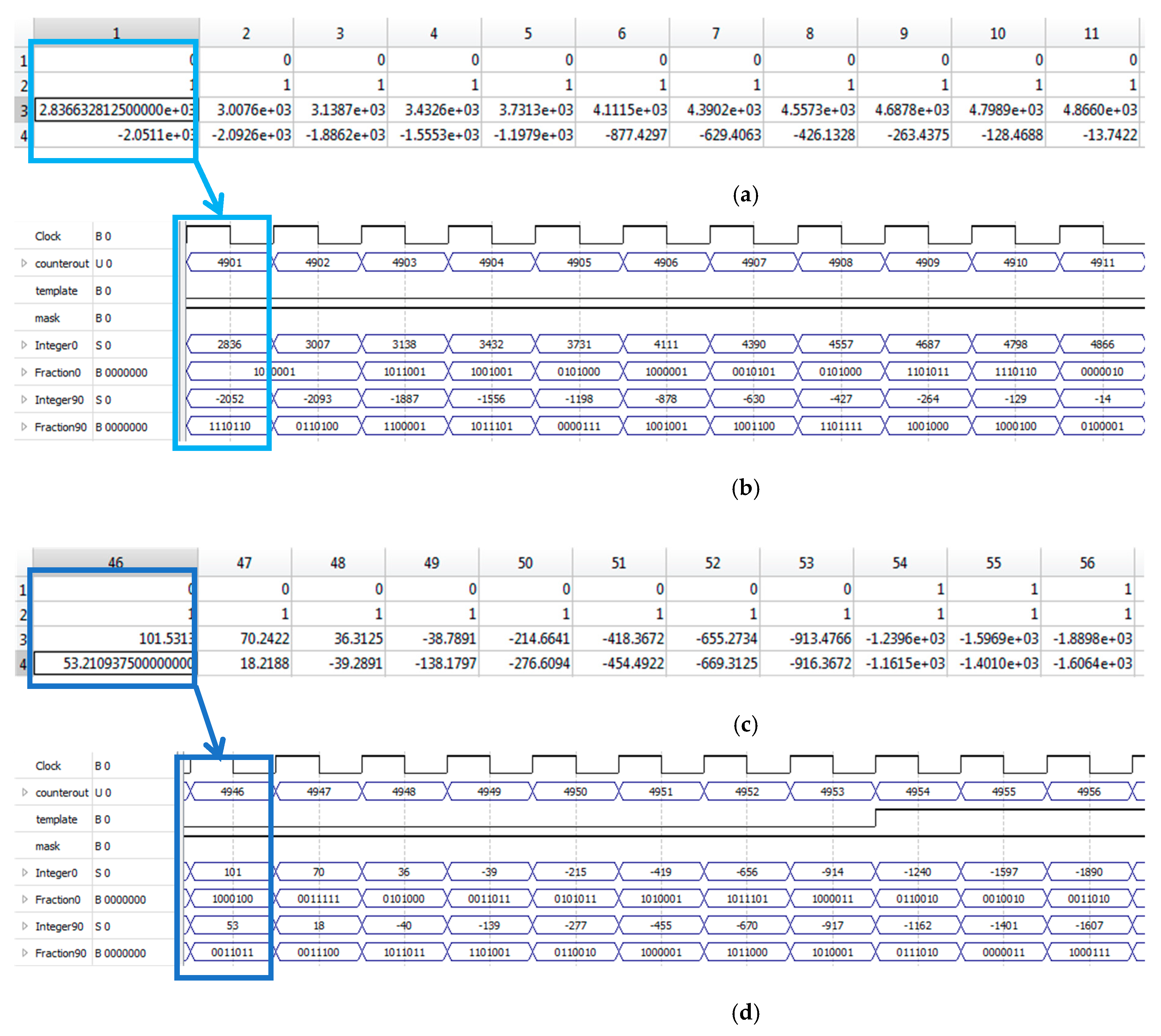
4.1. Iris Unwrapping Module

This module used around 6% of the logic element available on the targeted Cyclone V FPGA device. On average, the number of clock cycles needed to unwrap a single iris from a picture was found to be around 9156, which represents about a 45% reduction in the processing time (or 1.8× speedup) compared to the polar conversion technique. With a maximum clock frequency of 26.71 MHz, the proposed design can unwrap and produce a normalized template for about 2917 irises per second.
To validate the design, the proposed architecture was simulated using the Quartus Prime timing simulator tool. The output results during each clock cycle were captured and validated with the results from a software implementation of the algorithm. Table 1 shows a performance comparison with two previous works. Both previous papers presented unique ASIC designs dedicated to coordinate conversion, which is the main operation in the standard iris unwrapping process. As shown in Table 1, the proposed architecture’s performance compares well against other methods, even though the operating frequency is lower [28,29]. These performance values of other works were derived based on the assumption that each of the 16,560 bits (or pixels) in a template is generated based on the one-coordinate conversion.
The circle approximation method produces circle points that are very similar, but not identical, to the points produced using a conventional trigonometric-based method. Figure 13 shows a comparison of the two methods that are used for circle point generation. The maximum error occurs on the outer circle in the unwrapping portion of the algorithm. For the input image size of 320 × 240 pixels, the circle points have a Mean Squared Error (MSE) of 0.55 pixels. With a filter kernel size of 27 × 27 pixels, the resulting accuracy impact is negligible. It was demonstrated in a previous work that larger variations in measurement locations resulted in accuracy variations of less than 0.05 percent [30].

4.2. 2D Convolution (Filtering) Module

The architecture design for 2D convolution achieved a maximum clock frequency of approximately 214.13 MHz due to its pipelined parallel design. The total number of memory bits used in the convolution design is about 3% of the amount available on the targeted FPGA chip. Since the outputs of the iris unwrapping module are the inputs of the convolution module, they are synchronized to perform at the same rate, which is one pixel per clock cycle.
The entire feature extraction step, which involves both iris unwrapping and 2D convolution processes, was simulated in Quartus Prime software and the results were compared to the outputs obtained from a software implementation of the algorithm. The results are shown in Figure 14. The results shown in Figure 14a,c were obtained from the software implementation. The rows in Figure 14a,c represent the template, mask, and convolution filter outputs at 0° and 90°, respectively. The results shown in Figure 14b,d were obtained from the hardware design with Quartus Prime simulator tools. For Figure 14b,d, the labeled outputs template and mask represent the binary outputs of template A and mask A, respectively, from the convolution module. The outputs labeled Integer0 and Integer90 display the integer parts of the outputs from 2D convolution filters. The outputs labeled Fraction0 and Fraction90 display the fractional parts of the outputs in binary. Lastly, the output labeled counterout is a running count employed to track the outputs. As shown in the figure, the filter outputs are generated every clock cycle. Specifically, Figure 14a shows simulation results from a software implementation for a set of 11 pixels. Figure 14b presents simulation results from the proposed hardware implementation for the corresponding pixels. Figure 14c shows simulation results from a software implementation for another set of pixels. Figure 14d displays simulation results from the proposed hardware implementation for the corresponding pixels.

4.3. Template Matching Module

The template matching module was implemented using VHDL and it achieved a maximum clock frequency of approximately 196.58 MHz. The main computational tasks in this module are the division operations. Division operations in this work were achieved by subtraction operations in the logarithmic domain. The proposed architecture for the log2-based divider consumes 455 adaptive logic modules (ALMs) of an FPGA device, while the conventional FPGA-based divider utilizes 612 ALMs. This is equivalent to about a 25% reduction in the ALM resources.
To evaluate the impact of the approximation method on the overall Hamming Distance (HD) calculation, several template examples were used to compare the results of the proposed architecture and the conventional method. Table 2 provides a comparison for four example HD calculations. For this work, a template match that contains less than 50 percent valid pixels would be rejected by the algorithm. Therefore, the denominator of the division is an integer number that ranges from 8281 to 16,560, based on the template size of 92 × 180 pixels. Template matching produces a number between 0.0 and 1.0, denoting the quality of the match. To further test the impact of the approximate method of division, we tested all possible values the division could be performed on. Testing all possible numerator values for each denominator value gives 102,858,301 possible numerator/denominator pairs for the division operation. The MSE as a percentage of the division denominator is 0.000151 percent.

4.4. Complete Design

The feature extraction and template matching modules were integrated into a single design targeting a cost-effective Cyclone V FPGA device. The complete system achieved a maximum clock frequency of 25.38 MHz and the resource utilization is summarized in Table 3.
To validate the complete system design, images from the ICE benchmark database were used in the timing simulation using the Quartus simulator tool [31]. Several images from a subset of the ICE benchmark database were used for the performance analysis and the results are shown in Table 4. Note that the numbers shown in Table 4 are the clock cycle averages for the image subset.
For this analysis, a comparison of the proposed architecture and the conventional method was performed. The performance metrics for the conventional method were estimated based on a serial computational process of the trigonometric-based iris unwrapping, 2D convolution, and division-based template matching (HD). In addition, each arithmetic and memory operation in the conventional method was assumed to take one clock cycle. A summary of this comparison is shown Table 4. Since 2D convolution and template matching modules are pipelined in the proposed architecture and they operate on a fixed number of pixels in the template, their processing capabilities are combined in Table 4. If the conventional method is operated at the 100 MHz clock available on the FPGA platform, the average processing time required for one template is about 0.97 s. The average processing time for the proposed architecture is about 0.0011 s, which gives a speedup of about 881 times.

5. Conclusions

This paper has presented a novel architecture design for implementing the feature extraction and template matching processes in an iris recognition system. The iris unwrapping process was achieved by utilizing the efficient Bresenham circle algorithm to generate circle point locations in an iris image. This approach replaced trigonometric operations with simple add, subtract, and shift operations when a template was generated for an iris. The parallel architecture design was proposed for the 2D convolution process with efficient use of the FPGA’s embedded block RAMs for on-chip buffering. The on-chip buffering scheme allowed a processing rate of one pixel per clock cycle, without the need to access multiple pixels simultaneously. An approximation technique was used in the architecture design for the template matching module, in order to eliminate division operation in the algorithm. The simulation results have shown that the proposed architecture achieves significant speed up compared to the conventional method and it is suitable for real-time processing applications. For future work, the proposed design will be integrated with an embedded microprocessor and the iris boundary detection module via standard memory-mapped and streaming interfaces utilizing the input/output flexibility of an FPGA device. The successful integration of these components will provide a complete system-on-chip solution that is desirable for a portable iris recognition system.

Author Contributions

Conceptualization, H.N. and R.R.; methodology, H.N., R.R., and M.C.; software, R.B. and R.I.; validation, H.N., R.B., and M.C.; formal analysis, H.N., R.R., R.B., and M.C.; investigation, H.N., R.B., and M.C.; resources, R.B. and R.I.; data curation, H.N. and M.C.; writing—original draft preparation, H.N. and M.C.; writing—review and editing, H.N., R.R., R.B., and R.I.; visualization, H.N.; supervision, R.R. and R.I.; project administration, H.N. and R.R. All authors have read and agreed to the published version of the manuscript.

Funding

This research received no external funding.

Acknowledgments

The authors would like to thank the reviewers and editors for their reviews of this research.

Conflicts of Interest

The authors declare no conflict of interest.

References

  1. Prabhakar, S.; Ivanisov, A.; Jain, A. Biometric recognition: Sensor characteristics and image quality. IEEE Instrum. Meas. Mag. 2011, 14, 10–16. [Google Scholar] [CrossRef]
  2. Ammour, B.; Boubchir, L.; Bouden, T.; Ramdani, M. Face–Iris Multimodal Biometric Identification System. Electronics 2020, 9, 85. [Google Scholar] [CrossRef] [Green Version]
  3. Khan, M.K.; Zhang, J.; Horng, S.J. An effective iris recognition system for identification of humans. In Proceedings of the 8th International Multitopic Conference (INMIC2004), Lahore, Pakistan, 24–26 December 2004. [Google Scholar]
  4. Hsiung, T.W.; Mohamed, S.S. Performance of iris recognition using low resolution iris image for attendance monitoring. In Proceedings of the 2011 IEEE International Conference of Computer Applications and Industrial Electronics (ICCAIE), Penang, Malaysia, 4–7 December 2011. [Google Scholar]
  5. Agarwal, H.; Pandey, G.N. Online voting system for India based on AADHAAR ID. In Proceedings of the 2013 11th International Conference on ICT and Knowledge Engineering, Bangkok, Thailand, 20–22 November 2013. [Google Scholar]
  6. Ngo, H.; Rakvic, R.; Broussard, R.; Ives, R. Resource-aware architecture design and implementation of hough transform for a real-time iris boundary detection system. IEEE Trans. Consum. Electron. 2014, 60, 485–492. [Google Scholar] [CrossRef]
  7. Fang, B.; Lu, Y.; Zhou, Z.; Li, Z.; Yan, Y.; Yang, L.; Jiao, G.; Li, G. Classification of Genetically Identical Left and Right Irises Using a Convolutional Neural Network. Electronics 2019, 8, 1109. [Google Scholar] [CrossRef] [Green Version]
  8. Ives, R.W.; Broussard, R.P.; Kennell, L.R.; Rakvic, R.N.; Etter, D.M. Iris recognition using the Ridge Energy Direction (RED) algorithm. In Proceedings of the 42nd Asilomar Conference on Signals, Systems and Computers, Pacific Grove, CA, USA, 26–29 October 2008. [Google Scholar]
  9. Gupta, N.; Khosravy, M.; Gupta, S.; Dey, N.; Crespo, R.G. Lightweight Artificial Intelligence Technology for Health Diagnosis of Agriculture Vehicles: Parallel Evolving Artificial Neural Networks by Genetic Algorithm. Int. J. Parallel Program. 2020. [Google Scholar] [CrossRef]
  10. Rakvic, R.; Broussard, R.; Ngo, H. Energy Efficient Iris Recognition with Graphics Processing Units. IEEE Access 2016, 4, 2831–2839. [Google Scholar] [CrossRef] [Green Version]
  11. Kim, H.; Cho, J.; Jung, Y.; Lee, S.; Jung, Y. Area-Efficient Vision-Based Feature Tracker for Autonomous Hovering of Unmanned Aerial Vehicle. Electronics 2020, 9, 1591. [Google Scholar] [CrossRef]
  12. Aranda, L.A.; Sánchez, A.; Garcia-Herrero, F.; Barrios, Y.; Sarmiento, R.; Maestro, J.A. Reliability Analysis of the SHyLoC CCSDS123 IP Core for Lossless Hyperspectral Image Compression Using COTS FPGAs. Electronics 2020, 9, 1681. [Google Scholar] [CrossRef]
  13. Kwan, E.Y.L.; Nunez-Yanez, J. Entropy-Driven Adaptive Filtering for High-Accuracy and Resource-Efficient FPGA-Based Neural Network Systems. Electronics 2020, 9, 1765. [Google Scholar] [CrossRef]
  14. Huang, H.; Liu, Z.; Chen, T.; Hu, X.; Zhang, Q.; Xiong, X. Design Space Exploration for YOLO Neural Network Accelerator. Electronics 2020, 9, 1921. [Google Scholar] [CrossRef]
  15. Ea, T.; Valentian, A.; Rossant, F.; Amiel, F.; Amara, A. Algorithm implementation for iris identification. In Proceedings of the 48th Midwest Symposium on Circuits and Systems, Covington, KY, USA, 7–10 August 2005. [Google Scholar]
  16. Hematian, A.; Manaf, A.A.; Chuprat, S.; Khaleghparast, R.; Yazdani, S. Field programmable gate array system for real-time IRIS recognition. In Proceedings of the 2012 IEEE Conference on Open Systems (ICOS), Kuala Lumpur, Malaysia, 21–24 October 2012. [Google Scholar]
  17. Zaim, A.; Sawalha, A.; Quweider, M.; Iglesias, J.; Tang, R. A New Method for Iris Recognition using Gray-Level Coccurence Matrix. In Proceedings of the 2006 IEEE International Conference on Electro/information Technology, East Lansing, MI, USA, 7–10 May 2006. [Google Scholar]
  18. Bresenham, J.E. A Linear Algorithm for Incremental Digital Display of Circular Arc. Commut. ACM 1977, 20, 100–106. [Google Scholar] [CrossRef]
  19. Wright, W.E. Parallelization of Bresenham’s line and circle algorithms. IEEE Comput. Graph. Appl. 1990, 10, 60–67. [Google Scholar] [CrossRef]
  20. Carothers, M.T.; Ngo, H.T.; Rakvic, R.N.; Broussard, R.P. Iris unwrapping using the Bresenham circle algorithm for real-time iris recognition. In Proceedings of the SPIE/IS&T Electronic Imaging Conference, San Francisco, CA, USA, 8–12 February 2015. [Google Scholar]
  21. Sedaaghi, M.H.; Daj, R.; Khosravi, M. Mediated morphological filters. In Proceedings of the 2001 International Conference on Image Processing, Thessaloniki, Greece, 7–10 October 2001. [Google Scholar]
  22. Gutierrez, C.E.; Alsharif, M.R.; Khosravy, M.; Yamashita, K.; Miyagi, H.; Villa, R. Main large data set features detection by a linear predictor model. In Proceedings of the AIP Conference, Athens, Greece, 4–7 April 2014. [Google Scholar]
  23. Gutierrez, C.E.; Alsharif, M.R.; He, C.; Khosravy, M.; Villa, R.; Yamashita, K.; Miyagi, H. Uncover news dynamic by Principal Component Analysis. ICIC Express Lett. 2013, 7, 1245–1250. [Google Scholar]
  24. Bhuria, S.; Muralidhar, P. FPGA implementation of sine and cosine value generators using Cordic algorithm for satellite attitude determination and calculators. In Proceedings of the 2010 International Conference on Power, Control and Embedded Systems (ICPCES), Allahabad, India, 29 November–1 December 2010. [Google Scholar]
  25. Perri, S.; Spagnolo, F.; Frustaci, F.; Corsonello, P. Efficient Approximate Adders for FPGA-Based Data-Paths. Electronics 2020, 9, 1529. [Google Scholar] [CrossRef]
  26. Ngo, H.T.; Asari, V.J. Design of a Logarithmic Domain 2-D Convolver for Low Power Video Processing Applications. In Proceedings of the 6th International Conference on Information Technology: New Generations, Las Vegas, NV, USA, 27–29 April 2009. [Google Scholar]
  27. Mitchell, J.N. Computer multiplication and division using binary logarithms. IRE Trans. Electron. Comput. 1962, 11, 512–517. [Google Scholar] [CrossRef]
  28. Strollo, A.; De Caro, D.; Petra, N. A 430 MHz, 280 mW Processor for the Conversion of Cartesian to Polar Coordinates in 0.25 CMOS. IEEE J. Solid-State Circuits 2008, 43, 2503–2513. [Google Scholar] [CrossRef]
  29. Lee, S.; Kwon, K.; Park, I. Pipelined Cartesian-to-Polar Coordinate Conversion Based on SRT Division. IEEE Trans. Circuits Syst. II Express Briefs 2007, 54, 680–684. [Google Scholar] [CrossRef]
  30. Broussard, R.P.; Kennell, L.; Ives, R. Identifying discriminatory information content within the iris. In Proceedings of the SPIE 6944, Biometric Technology for Human Identification V, Orlando, FL, USA, 17 March 2008. [Google Scholar]
  31. Phillips, P.J.; Bowyer, K.W.; Flynn, P.J.; Liu, X.; Scruggs, W.T. The iris challenge evaluation. In Proceedings of the International Conference on Biometrics: Theory, Applications, and System, Washington, DC, USA, 29 September–2 October 2008. [Google Scholar]
Figure 1. Overview of the iris recognition system.
Electronics 10 00241 g001
Figure 2. Block diagram of the architecture design for the feature extraction and template matching processes in the iris recognition algorithm.
Electronics 10 00241 g002
Figure 3. Block diagram of the architecture design for the iris boundary detection module in the iris recognition algorithm.
Electronics 10 00241 g003
Figure 4. Illustration of pixel location generation using the Bresenham circle algorithm (BCA) method.
Electronics 10 00241 g004
Figure 5. Symmetry property in a circle used in the pixel coordinate generator.
Electronics 10 00241 g005
Figure 6. Illustration of the iris unwrapping process: (a) Input image; (b) pixel locations of a quadrant of a circle are calculated; (c) close-up view of one quadrant; (d) concentric circles encompassing the iris; (e) unwrapped iris without scaling; and (f) unwrapped iris with scaling.
Electronics 10 00241 g006
Figure 7. Pipeline architecture design for the unwrapping process: (a) Pixel location generator based on BCA and (b) template generator with a scaling factor.
Electronics 10 00241 g007
Figure 8. The 27 by 27 cosine kernel used in the design: (a) Cosine kernel shown in a three-dimensional plot; (b) top view of the cosine kernel in the horizontal (0°) direction; (c) top view of the cosine kernel in the vertical (90°) direction.
Electronics 10 00241 g008
Figure 9. Parallel architecture design for a 2D convolution module.
Electronics 10 00241 g009
Figure 10. Parallel architecture design for a 2D convolution module.
Electronics 10 00241 g010
Figure 11. Block diagram of the architecture design for the log2 approximation module.
Electronics 10 00241 g011
Figure 12. Block diagram of the architecture design for the template matching module.
Electronics 10 00241 g012
Figure 13. Circle points generated by the approximation method and the conventional trigonometric-based method.
Electronics 10 00241 g013
Figure 14. Simulation results of the 2D convolution (filtering) module: (a) Results from the software implementation of the filters; (b) corresponding results from the proposed hardware architecture showing one output per clock cycle; (c) results from the software implementation of the filters (another set of pixels); (d) corresponding results from the proposed hardware architecture showing one output per clock cycle.
Electronics 10 00241 g014
Table 1. Performance analysis of the iris unwrapping module.
TechnologyPerformance
(Cycle/Template Bit)
Clock Frequency
(MHz)
Average Unwrapping Time (µs)
Strollo et al. [28]0.25 µm CMOS13430500.65
Lee et al. [29] 0.25 µm CMOS 9400372.60
This workFPGA126.71342.79
Table 2. Comparison of the conventional method and the proposed method for Hamming Distance calculation.
Number of Non-Match PixelsNumber of Valid PixelsHD
(Conventional)
HD
(Proposed)
HD example 1200182850.24150.2428
HD example 23128 8945 0.3497 0.3589
HD example 3307913,7880.22330.2275
HD example 4696315,1370.46000.4630
Table 3. Implementation results for the complete feature extraction and template matching system.
DescriptionImplementation Result
Device5CGXFC9E7F35C8
Logic Utilization (ALM) 11,169 (10%)
Register Utilization 24,940
Memory Utilization (bits)1,125,024 (9%)
Block RAMs160 (3%)
Clock Frequency (MHz)25.38
Table 4. Performance analysis of the conventional method and the proposed method for iris template creation and template matching.
Conventional Method
(Clock Cycle)
Proposed Method
(Clock Cycle)
Iris Unwrapping82,8009156
2D convolution and HD96,644,16135,605
Total96,726,96144,761
Publisher’s Note: MDPI stays neutral with regard to jurisdictional claims in published maps and institutional affiliations.

