Article

Image Distortion and Rectification Calibration Algorithms and Validation Technique for a Stereo Camera

1
Korea Polytechnic VII, Changwon-si 51518, Korea
2
Korea Electrotechnology Research Institute, Changwon-si 51543, Gyeongsangnam-do, Korea
3
Department of Electrical Engineering, Yeungnam University, Gyeongsan 38541, Gyeongbuk, Korea
*
Author to whom correspondence should be addressed.
Electronics 2021, 10(3), 339; https://doi.org/10.3390/electronics10030339
Submission received: 19 December 2020 / Revised: 22 January 2021 / Accepted: 25 January 2021 / Published: 1 February 2021
(This article belongs to the Special Issue Applications of Computer Vision)

Abstract

:
This paper focuses on the calibration problem using stereo camera images. Currently, advanced vehicle systems such as smart cars and mobile robots require accurate and reliable vision in order to detect obstacles and special marks around. Such modern vehicles can be equipped with sensors and cameras together or separately. In this study, we propose new methodologies of stereo camera calibration based on the correction of distortion and image rectification. Once the calibration is complete, the validation of the corrections is presented followed by an evaluation of the calibration process. Usually, the validation section is not jointly considered with the calibration in other studies. However, the mass production of cameras widely uses the validation techniques in calibrations owned by manufacturing businesses. Here, we aim to present a single process for the calibration and validation of stereo cameras. The experiment results showed the disparity maps in comparison with another study and proved that the proposed calibration methods can be efficient.

1. Introduction

Currently, many sensors are being utilized in vehicles to reduce or lighten collision accidents. RADAR, single camera, and stereo camera sensors, in particular, are individually occupied or infused to avoid a forward collision. In particular, camera sensors are often applied to detect pedestrians, cars, traffic lights, signs, and other obstacles in the same way as drivers on a road [1,2,3]. It is preferred that a stereo camera distinguishes obstacles with ROI (Region of Interest) barriers as it uses sensor information and also includes distance information. Thus, it is useful to detect pedestrians as it has fast computation processing and vehicles using stereo camera are highly rated by the EURO NCAP (European New Car Assessment Program) standard. Moreover, it has many advantages such as monitoring the condition of the road surface (speed bumps, etc.), is appropriated in vehicle suspension control, etc.
Pre-processing is important for using a stereo camera sensor. Each camera acquires information on intrinsic parameters, extrinsic parameters, lens distortion coefficients, and proceeds to the calibration process [4,5]. While expensive equipment is required to improve the precision of calibration distortion, cheaper methods exist, such as using a circular marker in a three-dimensional cube to extract parameter information [6] and obtaining parameters based on different images from a two-dimensional checkerboard [7,8]. These days, self-calibration is introduced for a stereo camera [9]. Among these, a calibration method operating a plane checker is being widely expended, as shown by Zhang [8]. An algorithm is supported as a MATLAB Toolbox type [10]. It removes parallax in the vertical direction of images after the rectification process that aligns epipolar lines in calibrated left and right images [11]. The parallax of the right image that reflects the left image is measured using the rectified left and right images, and depth information is extracted [12,13].
For the mass production of a stereo camera sensor, the results obtained from the calibration process shall be numerically confirmed for the reduction defaults of the product. It is necessary to block defaults in advance as long as one numerically checks the distortion picture of a single camera image and the effect of image rectification on both cameras.
Even though numerous other methods exist, such as the use of photographs for certain calibration processes [14] and deal with a different laser beam [10], it is essential to reduce the process in the mass production of the component. Therefore, if the product assessment process is carried out with the process of calibration, a separate process can be reduced, which can lead to increase productivity. This study presents a method of modifying the form of the existing calibration checkerboard, extracting all parameters during the camera calibration process, and verifying defaults at the same time.

2. Related Work and Basic Theory

Camera calibration is a significant preprocessing task for using images. There are various known methods for the pre-processing task such as the radial alignment constraint [15], infrastructure-based calibration [16], and traditional pattern-based calibration algorithms [17], just to mention a few.
In the radial alignment construction technique, there is a 5-point pose estimator that seeks unknown radio distortion and local length without any calibration. It estimates a camera’s pose and parameters. There is also a way to automatically extract camera parameters by adding information to images in 3D point clouds [18].
In the infrastructure-based calibration, the external calibration method is used through SLAM (Simultaneous Localization and Mapping)-based feature point matching a multi-camera system based on infrastructure. The infrastructure-based calibration method is also used for extractions of single camera parameters and self-calibration during the operation of stereo cameras [19,20].
The pattern-based calibration methods are studied in the form of checkboards [17], AprilTags [21], geometry-based camera calibration [22] by arranging multiple patterns simultaneously on images [23], and calibrating values of camera calibration using distance sensors such as Lidar [24]. These methods estimate the camera’s internal and external parameters relatively accurately. However, one disadvantage of the pattern-based calibration algorithm is the inconvenience of obtaining the acquired patterns throughout an entire screen area by fisheye cameras. In addition, to do an estimation of the exact camera parameters requires the best close-range for improving the accuracy of the checker’s intersection and critical points, but it is difficult to have focus due to the acquirement images.
These above-mentioned studies are related to the extraction of camera parameters. However, the production process of the product requires process reduction, the accuracy of camera calibration is similar to that of the conventional method. In this work, we proposed a method to decrease production time by reducing the small process in manufacturing, which has the result of significant gains in production and cost. As a result, the current manufacturing process can diminish the steps in the calibration and validation at once.
Figure 1 shows how a stereo camera on a vehicle is typically built. The process begins with assembling a single camera and finishes with checking the distance. It can be seen that after the stereo camera assemblage, the internal and external parameters of images are extracted for correction of distortions. In general, the distortion correction process is based on a pinhole camera model to infer the lens distortion.
The principal of camera calibration is to analyze the conformity between an already defined three-dimensional dot and a two-dimensional projected dot [25]. The camera model is usually expressed like Equation (1):
w · [ x y 1 ] = k [ R t ] · [ X Y Z 1 ]
where the value w expresses the scale factor of object and image, while [R t] matrix defines the rotation and translation relationship between camera and object using extrinsic parameters, and k matrix is the intrinsic parameters of the camera.
Intrinsic parameters are defined in Equation (2). cx and cy are principal points, fx and fy are focal lengths, and α is the skew coefficient value between the x- and y-axis of the image plane, which is normally 0 in a digital camera. The dots on [ X Y Z ] are positioned in the image plane [ x n y n ] in a complete pinhole camera without distortion and can be expressed as Equation (3):
k = [ f x α c x 0 f y c y 0 0 1 ]
[ x n y n ] =   [ f x X Z f y X Z ]
If radial distortion is applied to [ x n y n ] and r2 means the distance from the main point, it can be represented as Equation (4). The addition of tangential distortion is indicated as Equation (5) [26]:
[ x r d y r d ] =   [ x n ( 1   +   k 1   *   r 2   +   k 2   *   r 4   +   k 3   *   r 6 ) y n ( 1   +   k 1   *   r 2   +   k 2   *   r 4   +   k 3   *   r 6 ) ]
[ x t d y t d ] =   [ x r d + [ 2 p 1 y n + p 2 ( r 2 + 2 x n 2 ) ] y r d + [ p 1 ( r 2 + 2 y n 2 ) + 2 p 2 x n ] ]
It can be described as Equation (6) if camera intrinsic parameters are considered [6]:
[ x n y n ] =   [ f x ( x t d + y t d ) a + c x f y y t d + c x ] .
Equation (1) eliminates the calculation of the Z part. Zhang’s Camera Calibration Algorithm [6] was adapted to solve the parameters using a Direct Linear Transform. The method of solving parameters using Zhang’s algorithm. Figure 2 shows the process of solving parameters by using Zhang’s algorithm and also performing rectification.
When the image calibration is finished, the mass production process performs the validation steps. During the validation process, image acquisition must be performed again.

3. Problems in the Existing Algorithms

In this paper, a checkerboard is used, which is composed of white and black squares in a repetitive pattern. This type of checkerboard has the benefit of a simple and correct extraction of a feature point, as the feature point is designated in the area where the white and black boundaries are in contact [27]. However, since a large-sized checkerboard is used in the mass production process, a problem might occur in the rectification process during an automated calibration process, as shown in Figure 3. Due to minor mistakes that arose from the left and right sides during the assembling phase of the cameras, there might appear to be a small height difference. At this point, an error was noticed during the matching process of the feature point, as seen in Figure 3. The default can be confirmed after going through a separate process.
In addition, since it is difficult to only use the checkerboard and estimate how much calibration is assumed and completed, a separate inspection process is required. A diamond-shaped pattern is accumulated in the checkerboard to solve such a problem, where black and white are repeated as displayed in Figure 4. Thus, this study presents a method of simultaneously verifying distortion and rectification errors, during calibration.

4. Solving Camera Calibration Techniques

4.1. Method of Detecting Squares and Diamonds in the Proposed Calibration Board

It is important to correctly identify the vertices in the proposed camera calibration board where white and black squares of the same horizontal and vertical lengths are in contact and use it as a camera’s calibration point. For this purpose, a method is proposed to recognize a square. First, a square’s characteristic is that it has the same length on its four sides and the same angle on its four corners. A binary image is generated using this function and a segment is identified where the difference between left- and right-sided pixel values is above a certain value. As exhibited in Figure 4, the squares on the calibration board are composed of white and black. It is applicable to differentiate pixels over adjacent squares that are often of a different color.
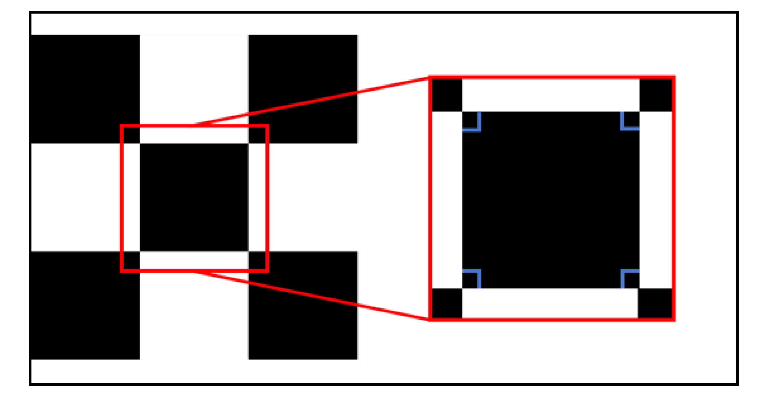
When a camera films the camera calibration screen, a camera-based 0 angle mistake indicates that the board is not rotated at all. This is when the square on the camera calibration board is expressed as a perfect square on the image taken. As indicated in Figure 5, all angles of the four corners are 90 degrees, which is characteristic of a square, and the vertices of the square can be detected using this.
The angle of the upper-left corner, which is the inclusive located angle between the upper-right and lower-left corners, shall be measured in the region observed. Then, the angle between the upper-left corner and bottom-right corner shall be calculated. As a result, the angles of all four corners shall be calculated and confirmed as to whether they are 90 degrees. If all the angles are 90 degrees at this point, it shall be determined as a square on the camera calibration board. With this method, the vertices of squares in the entire area on the taken image shall be detected. However, the filming may be done while the camera calibration board is not tilted at all. If a rotation has only occurred on a single axis among x, y, or z, in a three-dimensional environment, as shown in Figure 6a,b, a phenomena occurs when a distortion occurs on the x and y axes. This is distorted in the form of a rectangular shape due to different lengths of the horizontal and vertical axes, and Figure 6c shows the distortion of the angle to the z-axis, resulting in a tilted square resulting in a different reference line for estimating the angle of the square.
As revealed in Figure 7, not all angles of a square are 90 degrees if a rotation occurs on at least two axes. In this case, all angles of the square vary depending on the rotation axis and angle, and it becomes a simple square. The included angles are calculated using the outermost points in the area where the vertices are recognized. Then, if the dots are observed to have angles summed up as 360 degrees, it is calculated as a square using the adjacent outermost lines.
However, with many errors found in photographs taken in warehouses (factories), it is inadequate to evaluate it as a square by only using angles. Since there are many square-shaped product boxes and structures in factories, all of these objects become errors.
Next is a method of detecting diamonds on the camera calibration board. Although the shape of a diamond is a square that is rotated, because it has different side lengths than a square and its angles change based on the degree of rotation, its vertices cannot be detected accurately by only using the method of detecting squares. Figure 8 unveils a group of areas where squares are located. Since squares are located repetitively and disappear where diamonds exist, there is a high possibility that diamonds exist in gaps between the areas with squares. On a diamond basis, the check pattern is divided into Group 1 and Group 2. Matching points are extracted for each group.
The areas with a high chance of the existence of diamonds are set as ROI (Region of Interest). A diamond is a figure made with segments that are tilted at 45 degrees. Data with a similar form to the equation are searched using the equation of lines at 45 degrees and −45 degrees on the horizontal axis, and the parts that are outermost of these data are extracted. The diamonds used in the camera calibration board are black colored inside and all internal data is detected. Thus, from the detected data, the outermost angle data is used. At this point, intersection points are calculated using the outermost angle data which is extracted by the equation and these points are selected as vertices of the diamond.

4.2. Method of Verifying Distortion Calibration on the Proposed Calibration Board

Using vertices of the squares that are detected in Figure 8, the camera calibration is performed by Zhang’s algorithm among other camera calibration algorithms and the calculated camera parameters are used to perform a distortion calibration in the image. To check if the distortion calibration is well performed in the calibrated image, two methods are used.
The first method is to check whether vertices of other diamonds are located on a horizontal line that connects the leftmost and rightmost vertex of a diamond on the board. As shown in Figure 9, since diamonds on the board have the same size and are all parallel to each other, the upper vertex of diamonds that are located inside exist above the line that connects the vertex of diamonds located on the outermost.
Using this, if the vertex of diamonds positioned inside is located on the red line that connects the outer vertex of diamonds, the distortion calibration is determined to be performed well. If an error occurs, it is determined that there was an error in the number of pixels. As presented in Figure 10, the horizontal length of squares and diamonds is the same. If a line is made on the same vertical axis using the vertex of squares, it often goes through the vertex of diamonds.
The second method of verification uses the method of diamond line verification to match images captured on the same epipolar line from both cameras and rectify the two images. These rectified images are then located in the same epipolar line, as shown in Figure 11. Using the line that connects the vertex of diamonds on the image, the degree of alignment of lines generated on the two images is confirmed. If the line is off-angle (out of angle), the angle of distortion calibration and the error of position can be checked after examining the slopes and positions of the three-line pairs produced in the image.

5. Experiment

5.1. Experiment Environment

The stereo camera e-Intelligence production, which is an advanced driver assistant system corporation, was utilized for the camera used in the experiment (Figure 12). This is a camera with an Aptina™ AP0100 ISP (ON Semiconductor®, Phoenix, AZ, USA) applied to Aptina™ AT0132 CMOS (ON Semiconductor®, Phoenix, AZ, USA), and has a resolution of 1280 × 720. A board that can process results of Xilinx Virtex-7 FPGA (Xilinx, San Jose, CA, USA)and Depth Map in real-time. Additionally, the camera module is equipped with DS90UB913A (TI, Dallas, TX, USA), and the FPGA board is assembled with DS90UB914A (TI, Dallas, TX, USA) which transmits videos with LVDS communication. Since it is fitted with a video capture board WITH ROBOT for confirming videos at input and output terminals, a system that could perform real-time monitoring with USB 3.0 was used. The distance between the lenses of the two cameras is 300 mm.
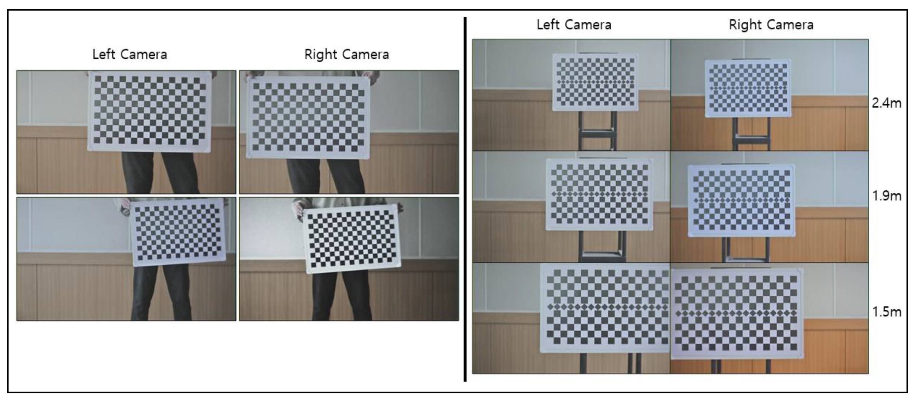
In order to use Zhang’s algorithm, the stereo camera was posed in 25 positions from the left and right sides in order to take images of the checkerboard. The proposed calibration board was also photographed at 0.1 m intervals between 1.5 m and 2.5 m distances. After obtaining about 200 images from the left and right sides for each step distance, calibration was performed using a total of 22 images, one for each distance. Figure 13 shows image acquisition.

5.2. Detection of Vertex of Squares and Diamonds

The camera calibration board used in the experiment as shown in Figure 14. It consists of two 5 × 18 groups consisting of white and black squares and 18 diamonds between two squares. The vertex of squares shall be detected to perform camera calibration. Square groups above and below the diamond in Figure 9 shall be determined, and it is ascertained by using the square detecting algorithm of Section 4.1.
Figure 15 displays that by a broad weight value, the data is modified to be closely contrasted for the correct identification of white and black figures in the picture. Then, the area where white comes in after black is set, and if this pattern is repeated over a certain time, it is set as an area with squares. Once the area with squares is set, the angle is calculated by using the outermost point of the boundary area between white and black. After calculating the angle, the vertex of squares is found. By detecting squares on the camera calibration board used in Figure 13, the result of detecting the vertex is indicated. Camera calibration is proceeded with the detected result by using dots on the camera calibration board.
Table 1 shows the camera’s parameters which are assumed by using camera calibration and is carried out in both the checkerboard, which is usually used for general camera calibration and the proposed calibration board. It can be seen that even if the diamond pattern is added to the camera calibration board, it shows no large errors in calculating the camera parameters.
This shows both the effects of the camera calibration using the normal white and black square camera calibration board and the camera calibration board with the inserted diamond pattern.
The distortion calibration is performed on the image by using the calculated camera parameters. Figure 16 shows the distortion correction that is calculated by the proposed method using the camera parameters illustrated in Table 1. Figure 16a,c shows the results of the distorted correction using Zhang’s algorithm, and Figure 16b,d depict the distorted correction using the proposed algorithm.
As asserted in Figure 17, the center of the square group is set as the diamond area because diamonds are located in the center of the square pattern. However, if the square area is generated incompletely, the widest area between squares is set as the diamond area and set as ROI. In the set ROI area, segments are made using the vertex of outermost diamonds and confirm whether the remaining vertex is on the segments.
As presented in Figure 18, three lines are made based on the horizontal axis and confirm whether each vertex is on the line, with the difference between the line and vertices set as an error.
Table 2 shows the error indicated on each line and vertices. Moreover, there is a check to see if the diamond vertex is positioned on a line made using the vertical axis of the squares, as seen in Figure 19. Since squares and diamonds are located parallel to each other on the camera calibration board, the vertical line of squares and locations of diamond vertex shall be consistent.
The difference between the line that connected vertical lines of squares and the vertex of diamonds are shown as calibration errors. Table 3 depicts pixel error between vertical lines of squares and diamonds.
To confirm the distortion calibration error of the two images, the line error is con-firmed using the diamond vertex from the rectified image. If the image is rectified accurately, the horizontal axis of the image aligns equally. Thus, the lines that connect diamonds in the two images shall be parallel to each other, or consistent. Figure 20 exhibits the lines that connect the diamond vertex on the image, which calibrated and rectified two images that are taken in the same location simultaneously. Calibration error can be confirmed by checking whether the three connected pair lines are compatible.
Figure 21 shows how much of the diamond vertex is on top of the line that is attached to the diamond vertex is proven in each non-calibrated and calibrated image, and each error is affirmed. The error of the vertex and lines in the non-calibrated image, as well as in the calibrated image, is indicated as the values in Table 4. The distortion calibration discloses that the error between the lines that connected diamonds and vertex is reduced, and it is possible to determine that the distortion calibration is performed well. Based on this data, it is possible to verify how accurately the distortion calibration is performed. Table 4 expresses the errors that occurred before and after the distortion calibration, using the calibration board in the experiment.
In the final experiment, we applied the camera parameters, which were obtained using Zhang’s algorithm and the proposed algorithm, for generating and comparing the disparity maps and depth maps. It can be seen in Figure 22, the images of the test object were taken every 0.1 m for each image starting from 1.5 m to 2.7 m distances for algorithm evaluation. Based on the images, the disparity maps and the depth maps were generated in Figure 23 and Figure 24, respectively.
In Figure 25, the results of the two algorithms were compared using the generated depth map. The analysis of the results in Figure 25 shows that the targeted validation process can be performed together with the camera calibration process to produce similar results.

6. Conclusions

Calibration using a stereo camera was carried by extracting vertex of squares, regarding a checkerboard composed of white and black squares. Since there is no verification method for the current camera calibration algorithm, it was utilized under the assumption that the calibration was performed well.
Camera calibration is a pre-processing work, which is used in all fields. It is an algorithm that calibrates distortions by assuming errors of the image sensor in cameras and lens parameters, and an essential algorithm for deriving accurate image processing results.
The algorithm proposed in this paper verified how accurately distortion calibration is innovated when images are calibrated using parameters that are assumed using a camera calibration algorithm. Since the existing algorithm has no method of identifying how accurately image distortion is calibrated, an algorithm for evaluating the accuracy is not being used. In particular, in the case of cameras used in products during the manufacturing process, it is necessary to perform camera calibration during the manufacturing process and identify whether the camera calibration is accomplished during the inspection process. Currently, a large number of stereo cameras are used in vehicles or on products with cameras installed. This study proposed a new type of camera calibration board to verify the distortion calibration of images, using camera parameters assumed by the correlation between two cameras. It used a board which added a diamond pattern to the existing checkerboard. Using the lines connected diamond vertex in the calibrated image, the rectilinearity of the board in the image was confirmed, errors of diamond vertex were magnified by connecting vertical lines of squares, and the accuracy of distortion calibration was verified. The level of distortion calibration could be checked by comparing pixel errors between the calibration of distortion using the proposed board and the verification algorithm and when calibration is not performed. Through a verification of distortion calibration, it is possible to assure whether camera calibration was assumed precisely and if not, then other methods such as moving the filming location of camera calibration could be used. For future studies, we are planning to experiment by adding another type of board for camera calibration and study an algorithm that can precisely recognize various types of patterns.

Author Contributions

J.K. and H.B. conceived and designed the paper concept. J.K. made the formal analysis. H.B. created the methodology. J.K. wrote the paper. H.B. provided the resource and software. S.G.L. supervised and edited the manuscript for submission. All authors have read and agreed to the published version of the manuscript.

Funding

This research received no external funding.

Conflicts of Interest

The authors declare no conflict of interest.

References

  1. Mercedes-Benz S-Class Stability System Uses Sensors, Stereo Camera. Available online: https://phys.org/news/2013-09-mercedes-benz-s-class-stability-sensors-stereo.html (accessed on 28 January 2020).
  2. Stereo Video Camera in Bosch Mobility Solutions. Available online: https://www.bosch-mobility-solutions.com/en/products-and-services/passenger-cars-and-light-commercial-vehicles/driver-assistance-systems/lane-departure-warning/stereo-video-camera/ (accessed on 28 January 2020).
  3. Subaru EyeSight. Available online: https://www.subaru.com/engineering/eyesight.html (accessed on 28 January 2020).
  4. Loop, C.; Zhang, Z. Computing rectifying homographies for stereo vision. In Proceedings of the IEEE Computer Society Conference on Computer Vision and Pattern Recognition, Fort Collins, CO, USA, 23–25 June 1999; Volume 1, pp. 125–131. [Google Scholar]
  5. Guan, B.; Shang, Y.; Yu, Q. Planar self-calibration for stereo cameras with radial distortion. Appl. Opt. 2017, 56, 9257. [Google Scholar] [CrossRef] [PubMed]
  6. Sturm, P.F.; Maybank, S.J. On Plane-Based Camera Calibration: A General Algorithm, Singularities, Applications. In Proceedings of the IEEE Conference on Computer Vision and Pattern Recognition CVPR, Fort Collins, CO, USA, 23–25 June 1999; pp. 432–437. [Google Scholar]
  7. Zhang, Z. A flexible new technique for camera calibration. IEEE Trans. Pattern Anal. Mach. Intell. 2000, 22, 1330–1334. [Google Scholar] [CrossRef] [Green Version]
  8. Heikkila, J.; Silven, O. A four-step camera calibration procedure with implicit image correction. In Proceedings of the IEEE Computer Society Conference on Computer Vision and Pattern Recognition, San Juan, PR, USA, 17–19 June 1997; pp. 1106–1112. [Google Scholar]
  9. Li, H.; Wang, K.; Yang, K.; Cheng, R.; Wang, C.; Fei, L. Unconstrained self-calibration of stereo camera on visually impaired assistance devices. Appl. Opt. 2019, 58, 6377–6387. [Google Scholar] [CrossRef] [PubMed]
  10. Gao, Z.; Zhang, Q.; Su, Y.; Wu, S. Accuracy evaluation of optical distortion calibration by digital image correlation. Opt. Lasers Eng. 2017, 98, 143–152. [Google Scholar] [CrossRef]
  11. Hartley, R.; Zisserman, A. Multiple View Geometry in Computer Vision; Cambridge University Press: Cambridge, UK, 2003. [Google Scholar]
  12. Dinh, V.Q.; Nguyen, T.P.; Jeon, J.W. Rectification Using Different Types of Cameras Attached to a Vehicle. IEEE Trans. Image Process. 2018, 28, 815–826. [Google Scholar] [CrossRef]
  13. Scharstein, D.; Szeliski, R. A Taxonomy and Evaluation of Dense Two-Frame Stereo Correspondence Algorithms. Int. J. Comput. Vis. 2002, 47, 7–42. [Google Scholar] [CrossRef]
  14. Oleksandr, S. Analysis of camera calibration with respect to measurement accuracy. In Proceedings of the 48th CIRP International Conference on Manufacturing Systems, Ischia, Italy, 17–19 June 2015; pp. 765–770. [Google Scholar]
  15. Kukelova, Z.; Bujnak, M.; Pajdla, T. Real-time solution to the absolute pose problem with unknown radial distortion and focal length. In Proceedings of the IEEE International Conference on Computer Vision, Sydney, Australia, 1–8 December 2013. [Google Scholar]
  16. Carrera, G.; Angeli, A.; Davison, A.J. Slam-based automatic extrinsic calibration of a multi-camera rig. In Proceedings of the International Conference on Robotics and Automation (ICRA), Shanghai, China, 9–13 May 2011. [Google Scholar]
  17. Zheng, Y.; Sugimoto, S.; Sato, I.; Okutomi, M. A general and simple method for camera pose and focal length determination. In Proceedings of the Computer Vision and Pattern Recognition (CVPR), Seattle, WA, USA, 21–12 June 2014. [Google Scholar]
  18. Camposeco, F.; Sattler, T.; Pollefeys, M. Non-parametric structure-based calibration of radially symmetric cameras. In Proceedings of the International Conference on Computer Vision (ICCV), Santiago, Chile, 7–13 December 2015. [Google Scholar]
  19. Dang, T.; Hoffmann, C.; Stiller, C. Continuous stereo self-calibration by camera parameter tracking. IEEE Trans. Image Process. 2009, 18, 1536–1550. [Google Scholar] [CrossRef] [PubMed]
  20. Rehder, E.; Kinzig, C.; Bender, P.; Lauer, M. Online stereo camera calibration from scratch. In Proceedings of the 2017 IEEEIntelligent Vehicles Symposium (IV), Los Angeles, CA, USA, 11–14 June 2017; pp. 1694–1699. [Google Scholar]
  21. Olson, E. Apriltag: A robust and flexible visual fiducial system. In Proceedings of the International Conference on Robotics and Automation (ICRA), Shanghai, China, 9–13 May 2011. [Google Scholar]
  22. Chuang, J.-H.; Ho, C.-H.; Umam, A.; Chen, H.-Y.; Hwang, J.-N.; Chen, T.-A. Geometry-based Camera Calibration Using Closed-form Solution of Principal Line. IEEE Trans. Image Process. 2021. [Google Scholar] [CrossRef] [PubMed]
  23. Zhang, J.; Zhu, J.; Deng, H.; Chai, Z.; Ma, M.; Zhong, X. Multi-camera calibration method based on a multi-plane stereo target. Appl. Opt. 2019, 58, 9353–9359. [Google Scholar] [CrossRef] [PubMed]
  24. Dhall, A.; Chelani, K.; Radhakrishnan, V.; Krishna, K.M. LiDAR-camera calibration using 3D-3D point correspondences. arXiv 2017, arXiv:1705.09785. [Google Scholar]
  25. Strger, C.; UIrich, M.; Wiedemann, C. Machine Vision Algorithms and Applications, 2nd ed.; Wiley-VCH: Weinheim, Germany, 2018; p. 219. ISBN 9783527413652. [Google Scholar]
  26. Bradski, G.; Kaehler, A. Learning OpenCV: Computer Vision with the OpenCV Library, 1st ed.; O’Reilly Media, Inc.: Newton, MA, USA, 2008; ISBN 0596516134. [Google Scholar]
  27. Sels, S.; Ribbens, B.; Vanlanduit, S.; Penne, R. Camera calibration using gray code. Sensors 2019, 19, 246. [Google Scholar] [CrossRef] [PubMed] [Green Version]
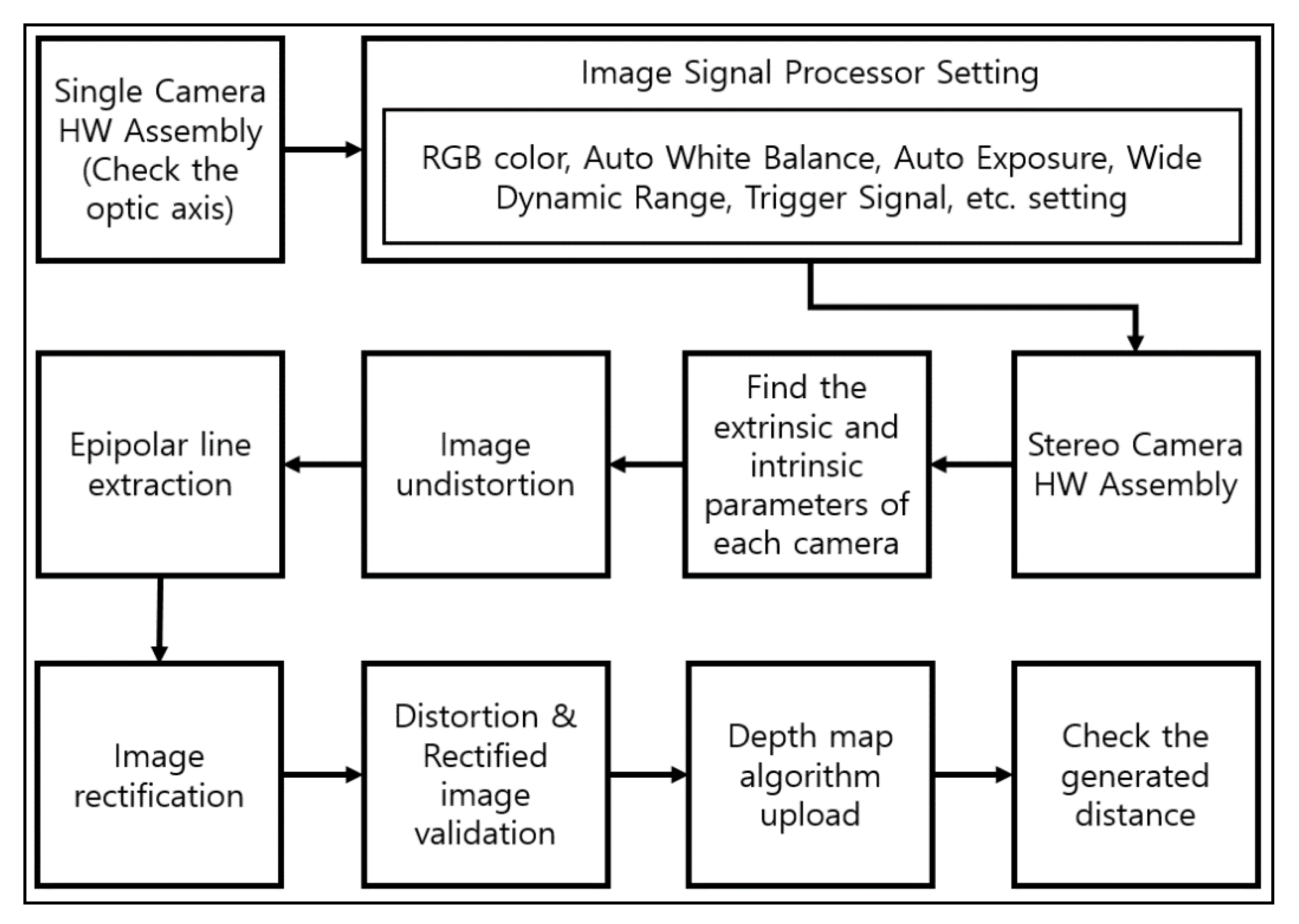
Figure 1. The process of making a stereo camera.
Electronics 10 00339 g001
Figure 2. The process from camera calibration to rectification using a checkerboard.
Electronics 10 00339 g002
Figure 3. Rectification error caused by a problem during the assembly process of the camera.
Electronics 10 00339 g003
Figure 4. The proposed calibration board.
Electronics 10 00339 g004
Figure 5. Angles of the four corners in a square without an angle error.
Electronics 10 00339 g005
Figure 6. Angles of a square when an angle error has occurred on a single axis in an image based on an x-y plane, (a) x-axis of the image, (b) y-axis of the image, and (c) z-axis of the image.
Electronics 10 00339 g006
Figure 7. The vertices of squares on the camera calibration board when an angle error occurs on at least two axes.
Electronics 10 00339 g007
Figure 8. Division of areas where squares exist.
Electronics 10 00339 g008
Figure 9. A segment using a vertex of diamonds.
Electronics 10 00339 g009
Figure 10. Verification using vertical segments of squares.
Electronics 10 00339 g010
Figure 11. Two rectified images, epipolar line, and diamond segments.
Electronics 10 00339 g011
Figure 12. Stereo camera used in the experiment.
Electronics 10 00339 g012
Figure 13. Stereo camera calibration using Zhang’s algorithm (left), and stereo camera calibration using the proposed calibration board (right).
Electronics 10 00339 g013
Figure 14. Proposed calibration board used in the experiment.
Electronics 10 00339 g014
Figure 15. Detection of the square vertex on the proposed calibration board.
Electronics 10 00339 g015
Figure 16. The results of the checkboard calibration of distortions: (a) Image corrected for distortion using Zhang’s algorithm, (b) image corrected using the proposed algorithm, (c) image corrected for distortion using Zhang’s algorithm, and (d) image corrected using the proposed algorithm.
Electronics 10 00339 g016
Figure 17. ROI (Region of Interest) of the area where diamonds exist (left), Image segmentation to extract diamond vertices (right).
Electronics 10 00339 g017
Figure 18. Diamond vertices extracted from the image (top), Straight line connecting diamond vertices (bottom).
Electronics 10 00339 g018
Figure 19. The vertex of diamonds located on vertical lines of squares.
Electronics 10 00339 g019
Figure 20. Lines that connect the diamond vertex on the rectified image.
Electronics 10 00339 g020
Figure 21. The error between lines and vertex of diamonds based on distortion calibration: (a) Rectify of the original image, (b) rectify of the calibrated image, (c) lines that are made using diamonds on the original image, and (d) lines that are made using diamonds on the calibrated image.
Electronics 10 00339 g021
Figure 22. Images of left and right cameras acquired for distance verification.
Electronics 10 00339 g022
Figure 23. The generation of the disparity map of Zhang’s algorithm and proposed algorithms.
Electronics 10 00339 g023
Figure 24. The generation of the depth map of Zhang’s algorithm and proposed algorithms.
Electronics 10 00339 g024
Figure 25. Comparison results with measurements using Zhang’s algorithm and proposed algorithms.
Electronics 10 00339 g025
Table 1. Camera parameters using normal checkerboard and the proposed calibration board.
Camera Parameters Using Normal Calibration BoardValuesCamera Parameters Using Proposed Calibration BoardValues
Camera 1 Focal Length2412.7, 2396.8Camera 1 Focal Length2073.3, 2067.9
Camera 1 Principal Point597.43, 386.15Camera 1 Principal Point592.529, 390.279
Camera 1 Radial Distortion−0.2534, 0.9139Camera 1 Radial Distortion−0.3626, 1.5353
Camera 1 Tangential Distortion−0.008, 0.00006Camera 1 Tangential Distortion−0.0076, 0.00221
Camera 2 Focal Length2448.6, 2435.1Camera 2 Focal Length2762.4, 2755.3
Camera 2 Principal Point607.87, 454.44Camera 2 Principal Point555.73, 400.17
Camera 2 Radial Distortion−0.1971, 0.2698Camera 2 Radial Distortion−0.4103, 3.9991
Camera 2 Tangential Distortion−0.0026, −0.003Camera 2 Tangential Distortion−0.0096, −0.0533
Table 2. The average error of pixel on vertices of each line by using diamonds.
LineAverage Error
Line 13
Line 24
Line 34
Table 3. Vertical lines of squares, the vertex of diamonds, and error.
LineAverage ErrorLineAverage ErrorLineAverage Error
Line 13Line 73Line 133
Line 24Line 84Line 143
Line 33Line 94Line 153
Line 43Line 104Line 162
Line 53Line 113Line 173
Line 62Line 123Line 183
Table 4. The error between lines using diamonds and vertex before and after distortion calibration.
Original Image-LineAverage ErrorUndistorted Image-LineAverage Error
Line 18Line 13
Line 210Line 24
Line 38Line 34
Publisher’s Note: MDPI stays neutral with regard to jurisdictional claims in published maps and institutional affiliations.