Article

Chaos-Based Secure Communications in Biomedical Information Application

1
Department of Engineering Science, National Cheng Kung University, Tainan 701401, Taiwan
2
Department of Biomedical Engineering, Hungkuang University, Taichung 433304, Taiwan
3
Department of Intelligent Commerce, National Kaohsiung University of Science and Technology, Kaohsiung 824004, Taiwan
*
Author to whom correspondence should be addressed.
Electronics 2021, 10(3), 359; https://doi.org/10.3390/electronics10030359
Submission received: 24 December 2020 / Revised: 24 January 2021 / Accepted: 27 January 2021 / Published: 2 February 2021
(This article belongs to the Section Systems & Control Engineering)

Abstract

:
Recently, with the rapid development of biomedical information, establishing secure communication and appropriate security services has become necessary to ensure a secure information exchange process. Therefore, to protect the privacy and confidentiality of personal data, in this study, we use a chaotic system, Lü system of the Lorenz-like system, to generate chaotic signals and apply them to encrypt the biomedical information. In addition, with one of the states of the chaotic system, we design a simple proportional-derivative (PD) controller to synchronize the master-slave chaotic systems for decrypting the biomedical information. Then, we encrypt the biomedical information, electrocardiography (ECG) and electromyography (EMG), measured about 30 s to 60 s to get tens of thousands of data from the subjects at the transmitting side (master) and send them to the receiving side (slave). After the receiving side receives the encrypted information, it decrypts them with the PD controller and then obtains the 1 mV to 2 mV biomedical signals. Thus, the security of the biomedical information can be ensured and realized.

1. Introduction

With the current rapid development of technology, several methods are available for information transmission, such as e-mail, cloud hard drive, and USB. However, with the advent of these methods, “information security” has become a crucial and inevitable concern. If information is stolen by others, it is likely to cause irreparable impact. Furthermore, people have recently started focusing considerably on the security of personal information, such as biomedical information with electrocardiograms and blood pressure; thus, the secrecy of personal biomedical information must be ensured. Therefore, designing an effective medical information encryption system is an important goal that we want to achieve. Traditional encryption methods can be classified into symmetric encryption (e.g., data encryption standard, DES) and asymmetric encryption (e.g., Rivest-Shamir-Adleman, RSA) [1]. The basic principle of symmetric encryption is to use Shannon’s concept of multiple encryptions and apply confusion and diffusion for converting plain text into other formats and spreading every small part of the plain text to each part of the ciphertext to encrypt the information.
So far, many asymmetric encryption methods have been proposed—such as RSA and ElGamal encryption—which use the property of homomorphism, multi-party computation, MPC, which breaks the secret into many shares, or chaotic systems in continuous-time domain which generates the random sequence. These encryption methods mainly use mathematical computation and encrypt important information to avoid its decryption.
However, whether RSA or ElGamal encryption, they need to consume large computation for power to encrypt and decrypt the data, and it will also take a lot of time and make the system delay. Moreover, in the worst situation, if someone wants to know the secret with multiparty computation, he or she could steal two keys and decrypt the ciphertext completely. In contrast, a chaotic system only needs simple computation with elementary arithmetic to maintain the security of the system, and, without enough data, at least about hundreds of data, no one can rebuild the system illegally. Thus, in this study, we chose to apply the chaotic system into communications in biomedical information.
In this study, because the chaotic system is extremely sensitive to initial conditions [2] and can generate the random sequence dynamically, we use digital signals generated by two discretized chaotic systems rather than the analog signals with the continuous system [3] to avoid the problem of the aging of electronic components [4] which may break down the stability of the chaotic system. With the chaotic digital signals, we encrypt the biomedical information and design a proportional-derivative (PD) controller to synchronize the systems, and then to recover the biomedical information.
In 1989, Ott et al. first proposed a method for controlling chaotic systems and named it the OGY method [5], from the names of Edward Ott, Celso Grebogi, and James A. Yorke. Subsequently, Pecora proposed the idea of synchronization control between two independent chaotic systems [6].
A chaotic system is a nonlinear dynamic one with complicated behaviors. This system was first used by Lorenz in 1963 in atmospheric simulation equations [7]. However, it did not attract the attention of scientists until 1978. Butterfly effects can be generated by slight changes in the initial conditions as well as by different attractors. There are various chaotic systems available, including the Hénon map [8], dynamic system in discrete time, Rössler attractor, and Lorenz oscillator, all of which are ternary nonlinear equations in continuous time.
Due to its complicated behaviors, the chaotic system has been employed in many domains, including communication, biology, mathematics, physics, chemistry, as well as economics [9]. Moreover, the hot topics of deep learning and image processing have also been widely applied for chaos theory so far [10,11]. Thereafter, controlling/synchronizing chaotic systems and their applications became the research focus on the literature [12].
The biomedical information collected in this study are extremely private signals, and thus, cannot be exposed in an unsafe space. Therefore, this study aims to encrypt, decrypt, and transmit the biomedical information safely. We develop a new type of encryption method that encrypts the information by using signals generated by the chaotic system and decrypts the encrypted information by the synchronization scheme with the signals and PD controller. We use the Lü system, which is related to the Lorenz oscillator (Lorenz-like system) and form two chaotic system in master-slave configuration that need to be synchronized with a proportional-derivative (PD) controller. In addition, we employ particle swarm optimization (PSO) to obtain the best parameters ( K p ,   K i , and K d ) and complete the synchronization of the two systems for correctly encrypting and decrypting the biomedical information.

2. Research Methods

2.1. Chaotic System

The Lü system generates ternary nonlinear equations in continuous time [13] as shown in Equation (1). x 1 , x 2 , and x 3 are the three states of the system. The system takes {a, b, c} = {36, 3, 20} as system parameters, and its dynamic matrix can be obtained in continuous time. To encrypt the biomedical information later, we will first discretize the system from continuous to discrete time with a sampling time of 0.0005 s.
{       x ˙ 1 = a ( x 2 x 1 ) x ˙ 2 = ( c a ) x 1 + c x 2 x 1 x 3 x ˙ 3 = b x 3 + x 1
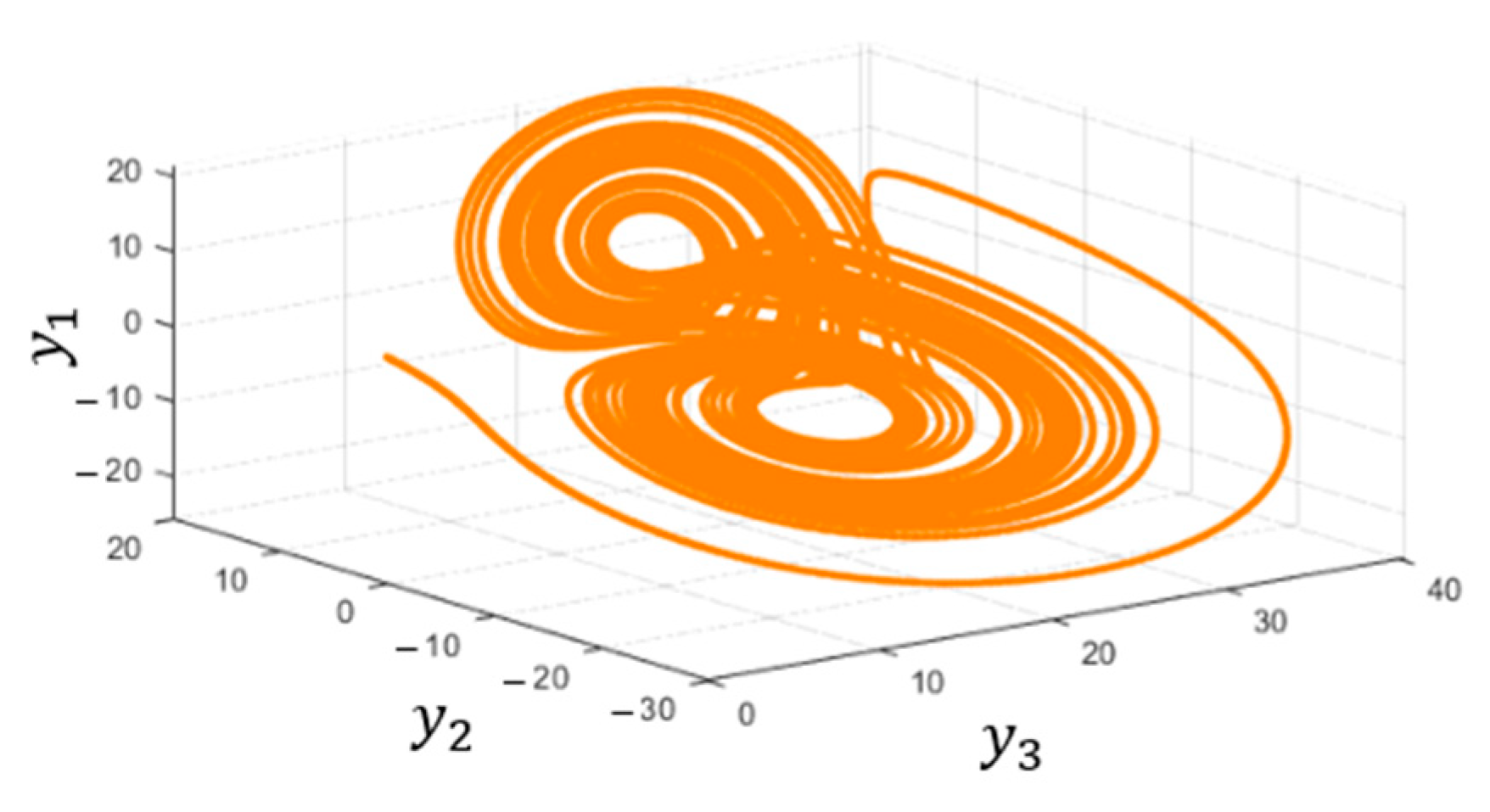
In this study, we use two chaotic systems—the transmitting side (master) with the state variables { x 1 , x 2 , x 3 } and the receiving side (slave) { x ¯ 1 , x ¯ 2 , x ¯ 3 } , but with the different initial conditions of { x 1 0 , x 2 0 , x 3 0 } = { 4 , 3 , 2 } and { x ¯ 1 0 , x ¯ 2 0 , x ¯ 3 0 } = { 8 , 1 , 5 } . Figure 1 and Figure 2 depict the responses of the chaotic system in master chaotic system and slave chaotic in three dimensions with double-scroll attractor, respectively.

2.2. PD Controller Synchronizing Chaotic Systems

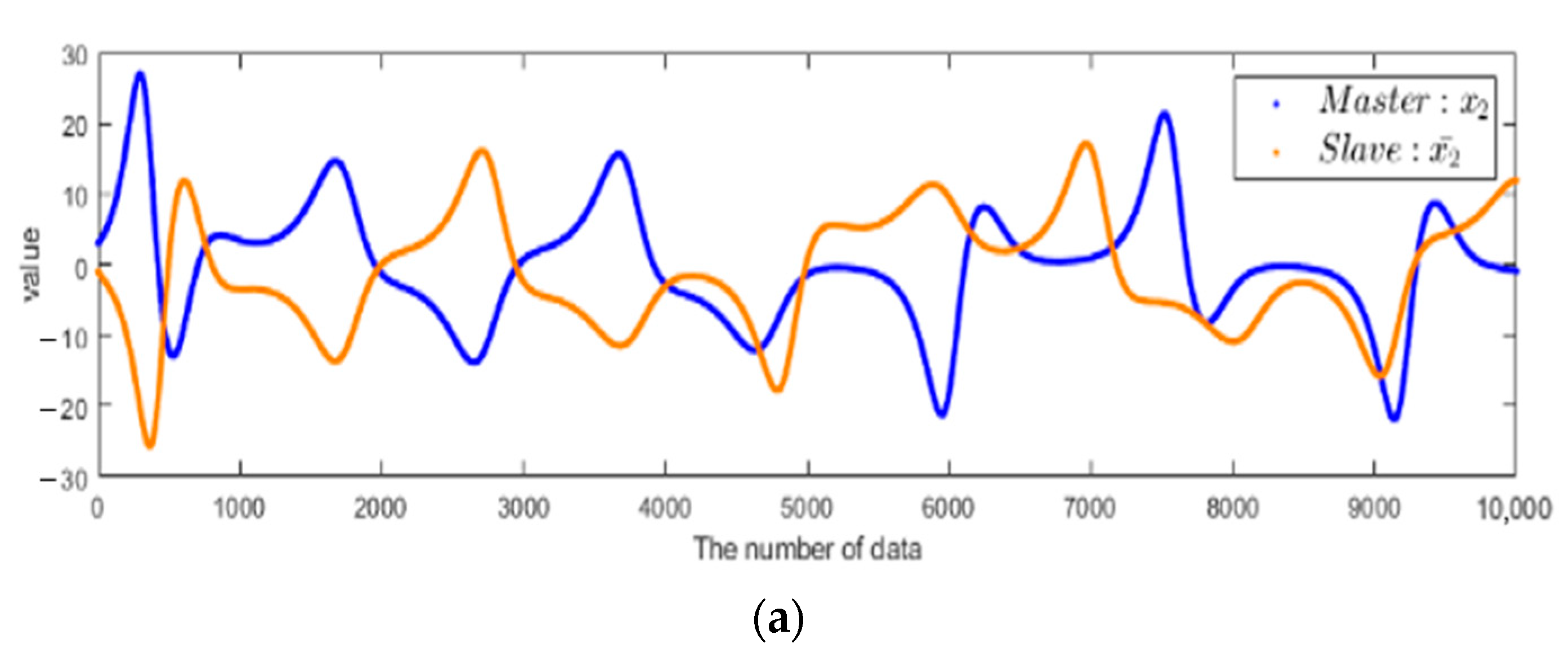
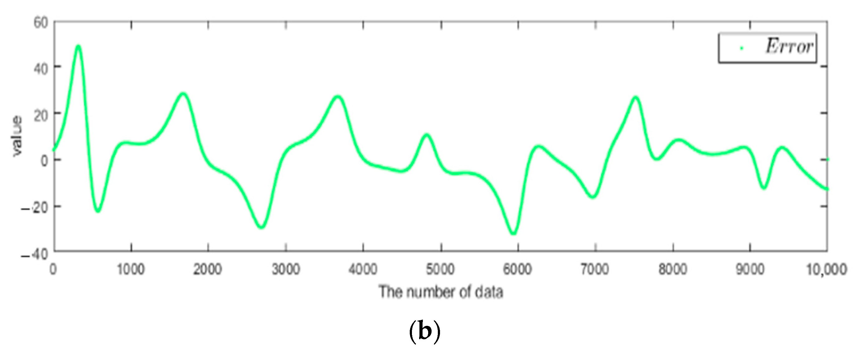
In the Lü system, x 1 , x 2 , and x 3 affect each other, and thus, we employ the PD controller in one of the states of the chaotic system for synchronization. In this study, we control the second states,   x 2 and x ¯ 2 , of the systems. Figure 3 shows the states x 2 and x ¯ 2 of the master and slave before the application of the PD controller; the error falls between −40 and 60.
Then, we add controller un to the equations in discrete time at the slave for synchronization, as shown in Equation (2) where Q = 4.488 × 10 6 .
x 1 ¯ n + 1 = 0.9822 x 1 ¯ n + 0.01793 x 2 ¯ n Q x 1 ¯ n x 3 ¯ n x 2 ¯ n + 1 = 1.01 x 2 ¯ n + 5.02 × 10 4 x 1 ¯ n x 3 ¯ n + u n x 3 ¯ n + 1 = 0.9985 x 3 ¯ n + 4.996 × 10 4 x 2 ¯ n x 3 ¯ n
un is the synchronization controller includes proportional and differential controller as shown in Equation (3). The proportional controller (Kp) will consider the current error to speed up the time of the transient response so that the chaotic system, slave, will turn into a steady-state and synchronize with master as soon as possible. Furthermore, once the proportional controller over controls the system, the overshooting will occur. So, here we are going to use the differential controller (Kd) to make the system smoother. The differential controller will use the future error to predict the tendency of the system so that it can decrease the rise time and avoid overshooting.
u n = K p e n + K d Δ e n
In case of the controller design, we use PSO (particle swarm optimization [14]) to determine the optimized parameters of PID. PSO is a computational method that optimizes a problem by iteratively trying to find the best candidate solution with random particles. In the time t , the position, X i t ,   and velocity, v i t , of i t h   particle will be decided from the particle’s, P i (personal best), and particles’, G i (group best), experience where { w , c 1 , c 2 , r 1 , r 2 } = { 0.7 , 2 , 2 , 0.6 , 0.3 } , w is the inertia weight, c 1 and c 2 are acceleration constants for itself and the group, and r 1 and r 2 are the random numbers in [0, 1]. The initial conditions of X i t and v i t are randomly distributed in [0, 0.5] and [0, 1], respectively, where X i t is a set of optimized parameters of K p ,   K i ,   K d .
In each iteration, we make the chaotic systems with the PID controller run 1000 times, and its fitness function is the sum of squared errors of the three states in the Master and Slave.
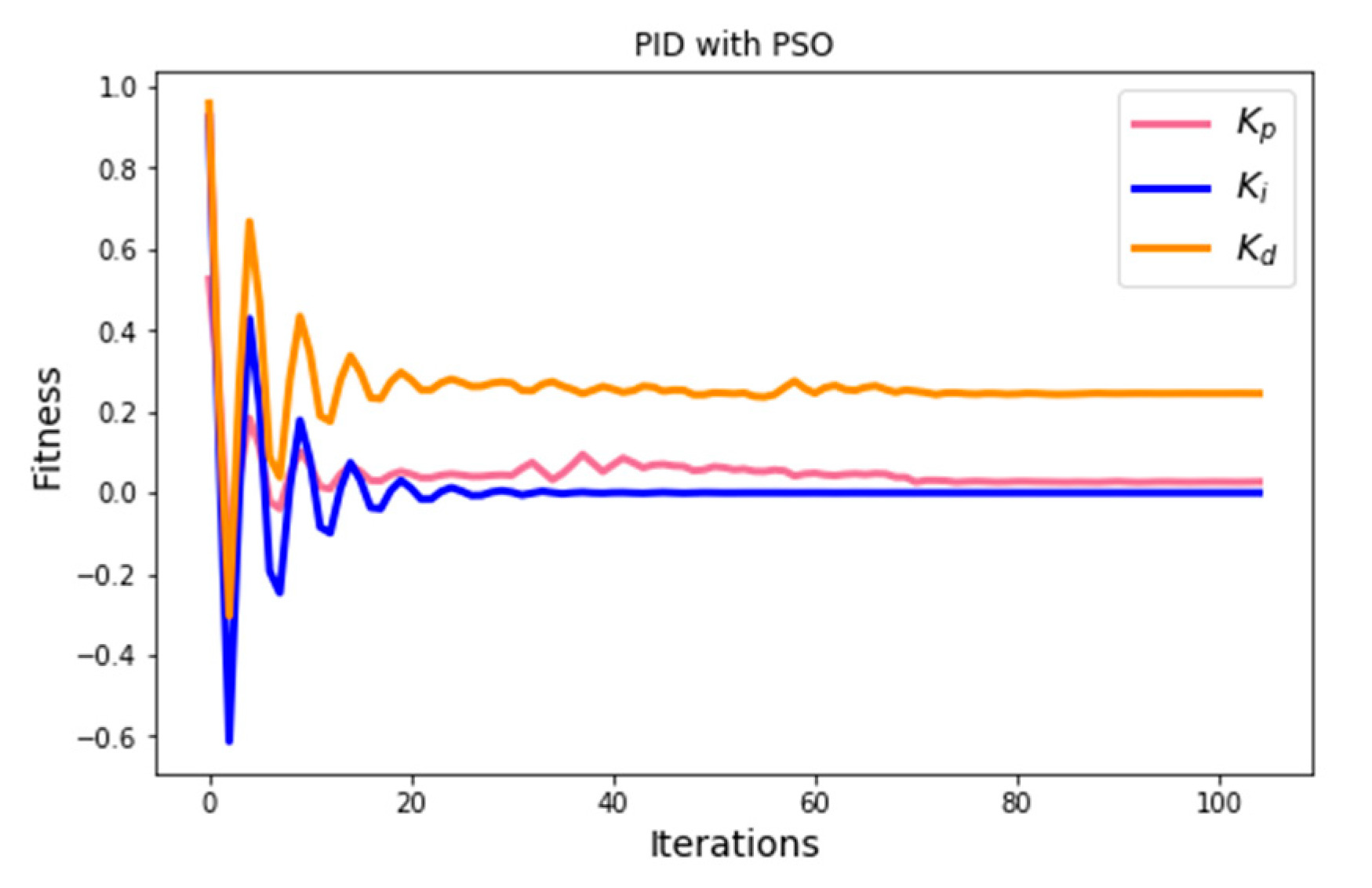
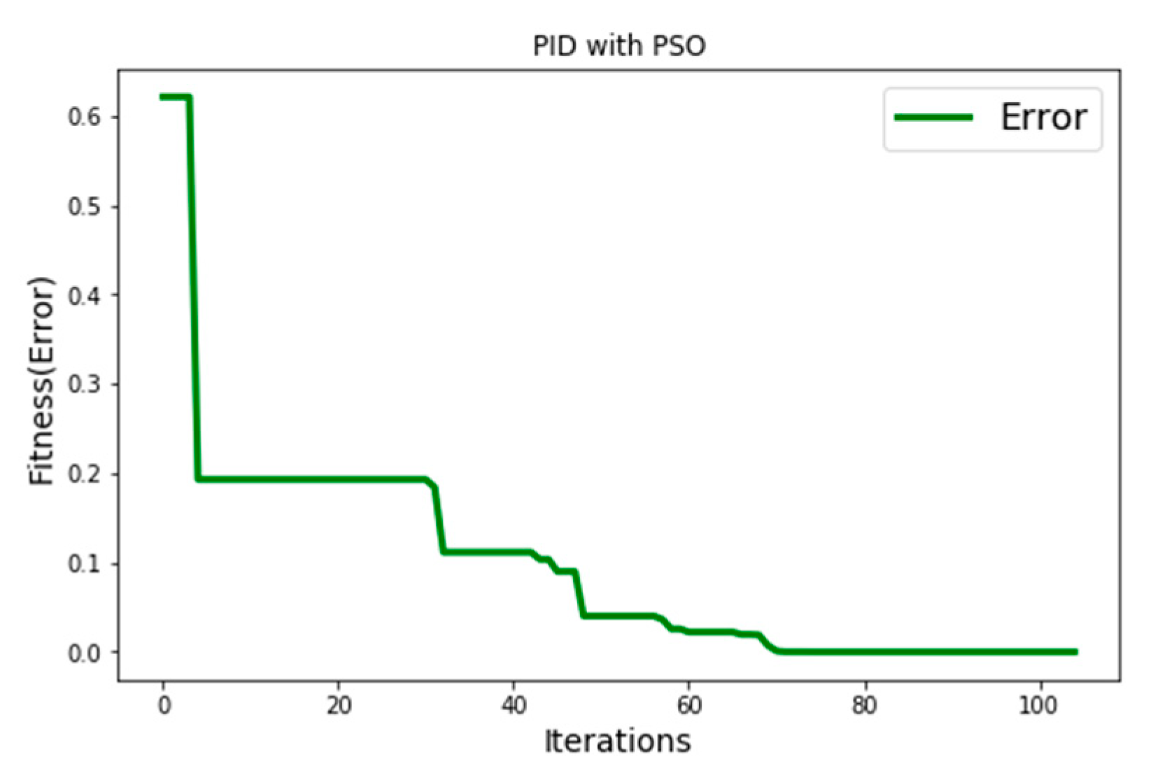
Figure 4 and Figure 5 show that after 99 iterations, the optimized parameters of X i t ( K p ,   K i ,   K d ) converged to a steady state, and the sum of the errors converged to less than 10 7 , where { K p , K i , K d } { 2.582 × 10 2 , 3.793 × 10 8 , 1.331 × 10 1   } . In addition, K i is nearly equal to zero; thus, we set the K i as 0, and that is the reason that we only use the proportional–derivative controller in this study. The optimized parameters used are obtained from 10 datasets with a steady value of X—which are the averages of the 89 t h to 99 t h datasets, where { K p , K i , K d } { 0.0257 , 0 , 0.133 } .
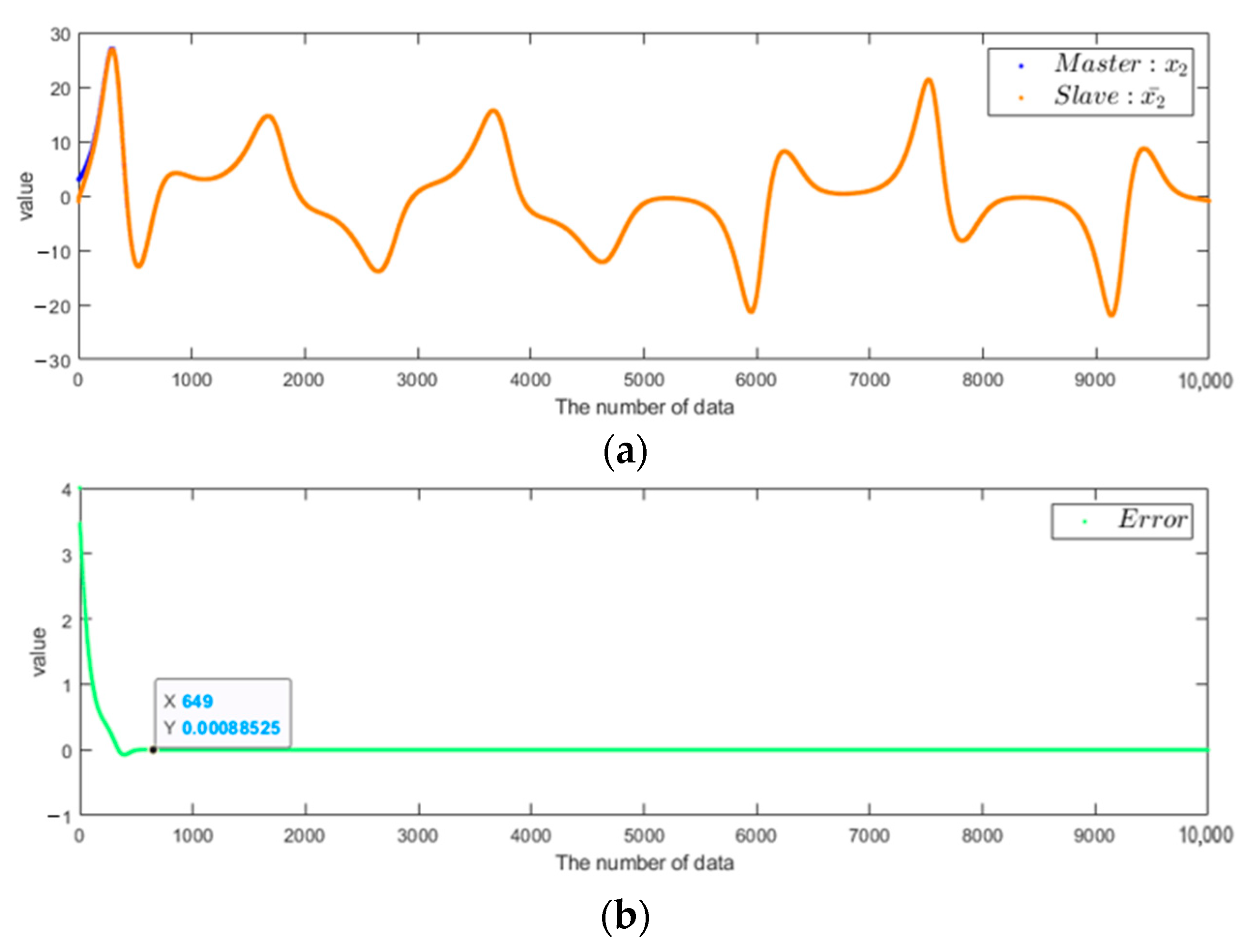
After the optimized parameters are obtained, the second states, x 2 and x 2 ¯ , of the master and slave, respectively, are found to be successfully synchronized, with an error of less than 10 3 at approximately 649 iterations. Figure 6 shows diagrams of the second states of the master and slave with the PD controller as well as their errors.

2.3. Biomedical Information

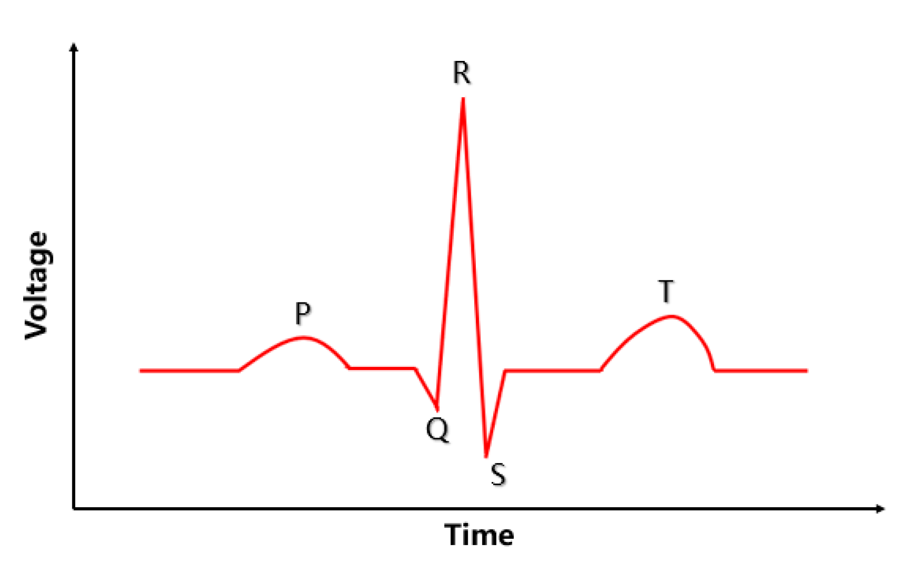
In this paper, for biomedical information, we use electrocardiography (ECG) and electromyography (EMG) signals. After data collection, we use ECG and EMG information to observe the relationship between encryption and decryption. The ECG is shown in Figure 7. Moreover, we consider PQRST which means P wave, QRS complex, and T wave [15]. In the ECG, by using the collected data, we calculate the number of heartbeats with R-R interval. In the EMG, we observe the amplitude and peak.

3. Information Security

3.1. Stability of the Chaotic System

After generating the chaotic signals in the discrete-time domain, now, we are going to prove that the generated signals are random sequences with National Institute of Standards and Technology (NIST) Statistical Test Suite (SP 800-22) [16].
NIST Statistical Test Suite includes 15 test items to judge whether the generated sequence is a random sequence or not. If the p-value in the items is lower than 0.01, we will say that the sequence is non-random. Otherwise, the sequence passes the NIST test and is random. The higher the p-value which means the sequence are random better. Thus, to verify the stability of the chaotic system, we apply the second state of the system to NIST Statistical Test Suite. The result is as shown in Table 1 which each value is calculated by average.
In Table 1, all the p-value are higher than or equal to 0.01, and the average is about 0.5. Here, we know that the chaotic system we proposed passes all NIST test items. Therefore, we can conclude that the discretized chaotic system can truly generate random sequences so that we can encrypt the data with them [17].

3.2. Security of the Chaotic System

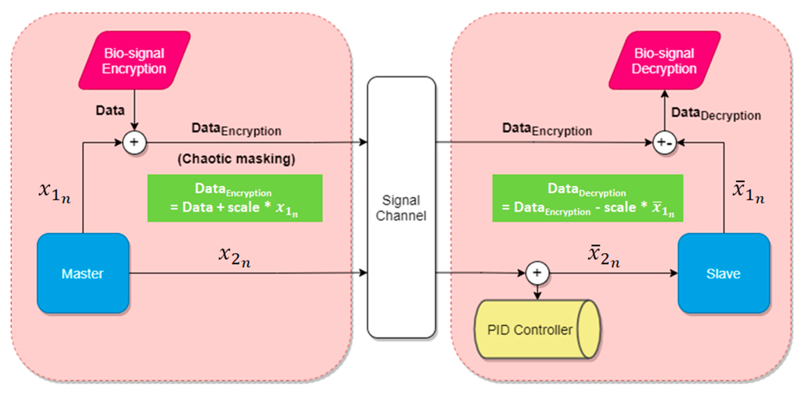
In this study, we use the PD controller to synchronize the master-slave chaotic systems, which uses the error to adjust the controller and synchronizes the system. Thus, one of the states of the chaotic system must be transmitted simultaneously with the encrypted data. The architecture of secure biomedical system is shown in Figure 8.
In the transmitter side (master system), x 1 n is used in the encryption algorithm via chaotic masking method and x 2 n is used for the chaos synchronization by the PD controller design; thus, x 2 n is sent to the slave. Therefore, we must prove here that even if someone steals the several transmitted data (encrypted data and x 2 n where the data is not enough or less than 649 data for synchronization), neither the encrypted data nor the chaotic system will be cracked. The equations of the chaos system in the master are shown below where Q = 4.488 × 10 6 .
x 1 n + 1 = 0.9822 x 1 n + 0.01793 x 2 n Q x 1 n x 3 n x 2 n + 1 = 1.01 x 2 n + 5.02 × 10 4 x 1 n x 3 n x 3 n + 1 = 0.9985 x 3 n + 4.996 × 10 4 x 2 n x 3 n
Assuming that each encrypted datum and x 2 n are stolen by the stealer, from the perspective of the stealer, he may derive the Equation (4) from the stolen data. Because of the stolen data, some of the unknown variables such as x 2 n , x 2 n + 1 , and x 1 n x 3 n will change from unknown variables to known variables. Here, we use α , β , and γ to represent the variables which are known by the stealers where α is the known x 2 n , β is the known x 2 n + 1 , and γ is the known x 1 n x 3 n .
x 1 n + 1 = 0.9822 x 1 n + 0.01793 α Q γ β = 1.01 α + 5.02 × 10 4 γ x 3 n + 1 = 0.9985 x 3 n + 4.996 × 10 4 α x 3 n
Equation (5) shows that owing to the stolen data, the system of three equations become a system including only two equations. However, there are still four unknowns ( x 1 n , x 1 n + 1 , x 3 n , and x 3 n + 1 ); thus, even if some information is stolen accidentally, the stealer still cannot solve the four variables from only two equations. Therefore, despite the risk of x 2 n being stolen, the chaotic system maintains a high level of confidentiality.

3.3. Information Security

However, once the hacker gets enough data, he can decrypt the encrypted information by synchronizing the system rather than knowing all the states of the chaotic system. Thus, here we are going to discuss the information security by time complexity of computational complexity.
Assume that there are n data stolen where n is higher than or equal to 649. The time complexity of successfully synchronizing the proposed system is O(649) to O(n). This means that without at least 649 data for iterations, no one can decrypt the encrypted information. Moreover, without the proper parameters of the PD controller, the worst time complexity will be O(n) which means the system needs at least n iterations for synchronization.
As mentioned above, the chaotic system maintains a high level of confidentiality, so that irrespective of x 1 n or x 1 n + 1 being stolen, the stealer has no information. Therefore, we can use x 1 n to encrypt the information without it being cracked by someone.

4. Architecture of the System and Simulation

4.1. Information Security

First, we collect the biomedical information, ECG or EMG bio-signals, from the subjects with a wireless multi-channel physiological signal recording system (TD3, GPU123 Technology Co., Ltd., Taoyuan, Taiwan). Then, the raw data are sent to a computer via a USB wireless receiver. In the following, a simulation part and an implementation part will be discussed. The architecture of the system is shown in Figure 9.
In the simulation part, the raw data are executed, and the master and the slave are simulated through a computer program. Then, a relevant diagram is drawn for analysis and comparison. In the implementation part, Raspberry Pi is used to execute the programming and read the raw data. Then, the master sends the data to the slave with universal asynchronous receiver/transmitter (UART) [18]. After the data transfer is completed, the relevant diagram is drawn.

4.2. Collection of Biomedical Information

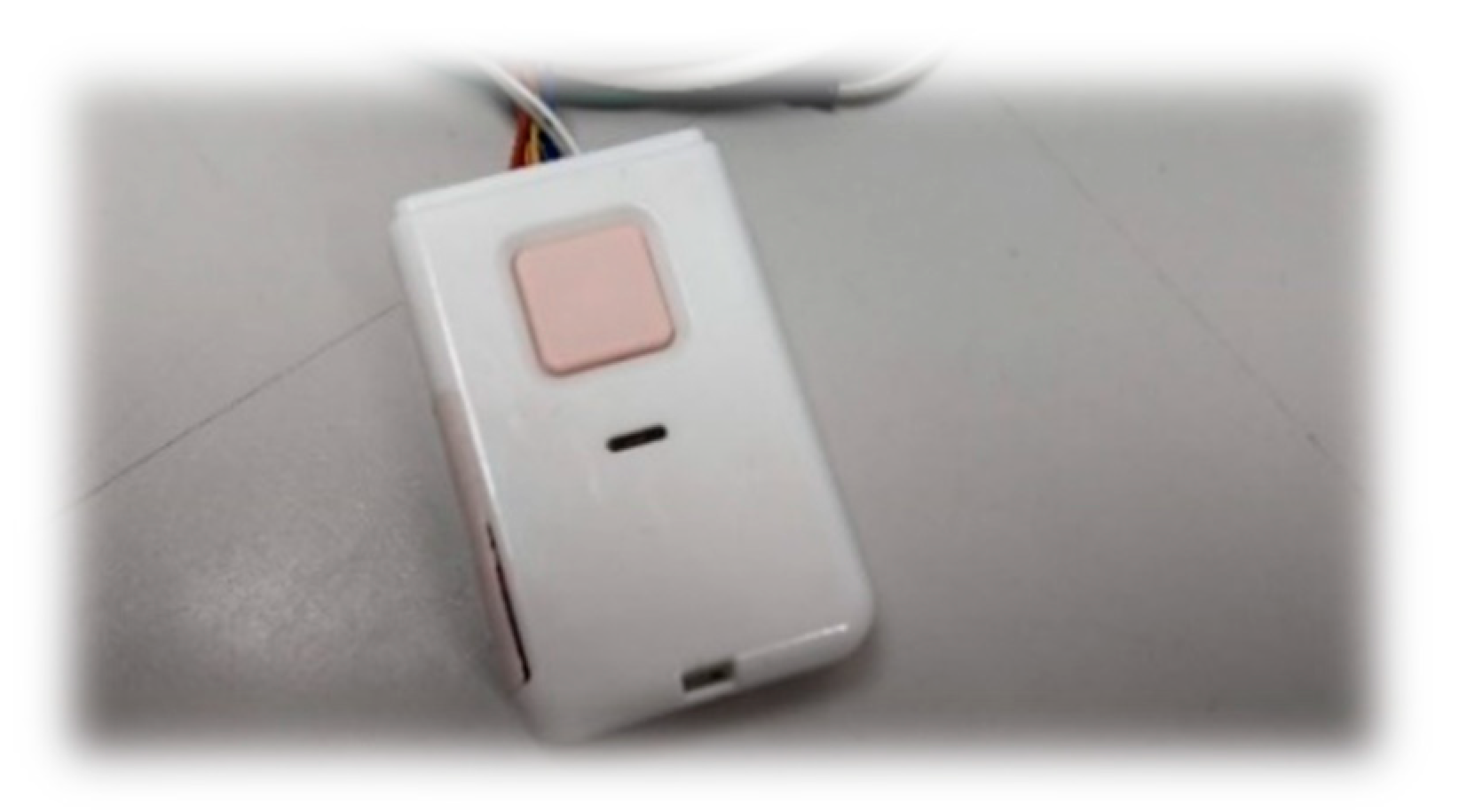
In this study, we use TD3 shown in Figure 10 to receive ECG and EMG bio-signals, with sampling frequencies of 250 Hz and 125 Hz, respectively. The data points obtained from TD3 are 8-bit data, and their values range between 0 and 255.
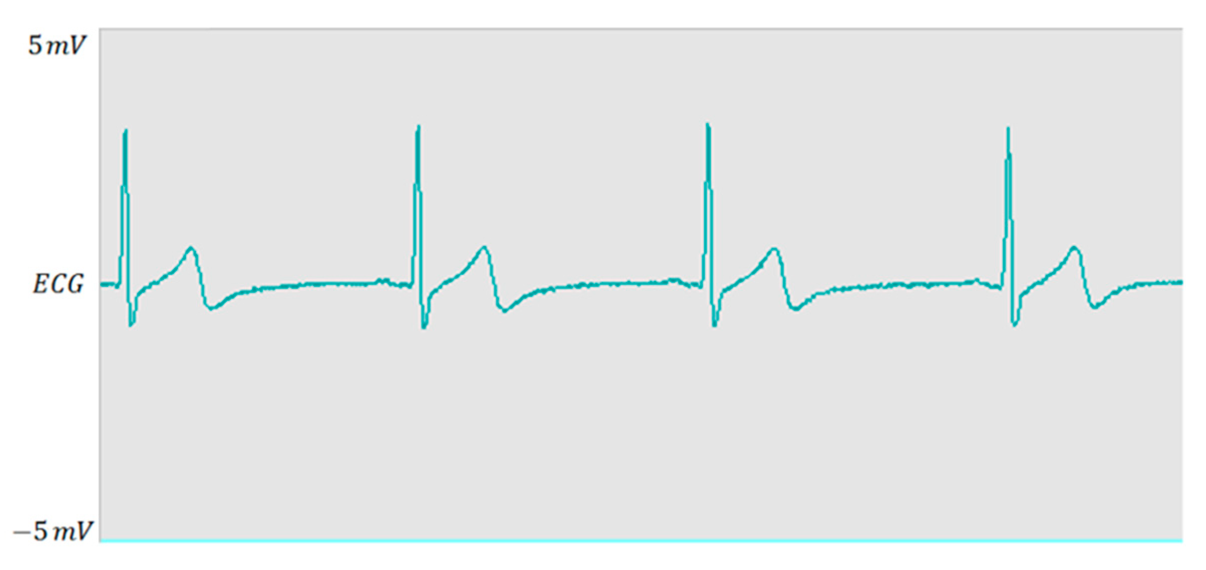
In case of ECG, we attach a bio-signal sensor patch immediately below the heart in the body. This test lasts for 32 s with 16,080 data points, where the maximum amplitude is ~2 mV, as shown in Figure 11.
In case of EMG, the bio-signal sensor patches are attached to the biceps of the left arm. In the test, we start from the arm in a free-fall state (0°) to the arm perpendicular to the body (90°), lifting approximately 2 kg of object every four seconds, as shown in Figure 12. The test lasts for 62 s with 31,136 data points, with a maximum amplitude of approximately 2 mV, as shown in Figure 13.

4.3. Encryption and Decryption of the Data

In case of encryption, a chaotic masking method is applied for encrypting the biomedical information in the master by adding x 1 n multiplied by a scale. The encryption algorithm is given below:
Data Encryption =   Data + scale × x 1 n
For decryption, by contrast, we decrypt the encrypted data in the slave by subtracting x 1 ¯ n multiplied by the same variable:
Data Decryption =   Data Encryption scale × x 1 ¯ n

4.4. Simulation and Verification of the Chaotic System

If the chaotic system in the slave is successfully synchronized with that in the master, when a state of the system is randomly selected from both systems, the same response [19] of the chaos system is obtained in the master. Figure 14 indicates that the two chaotic systems are completely synchronized, where the responses of the two states are randomly selected from the Master and Slave.

4.5. Simulation and Verification of EMG and ECG

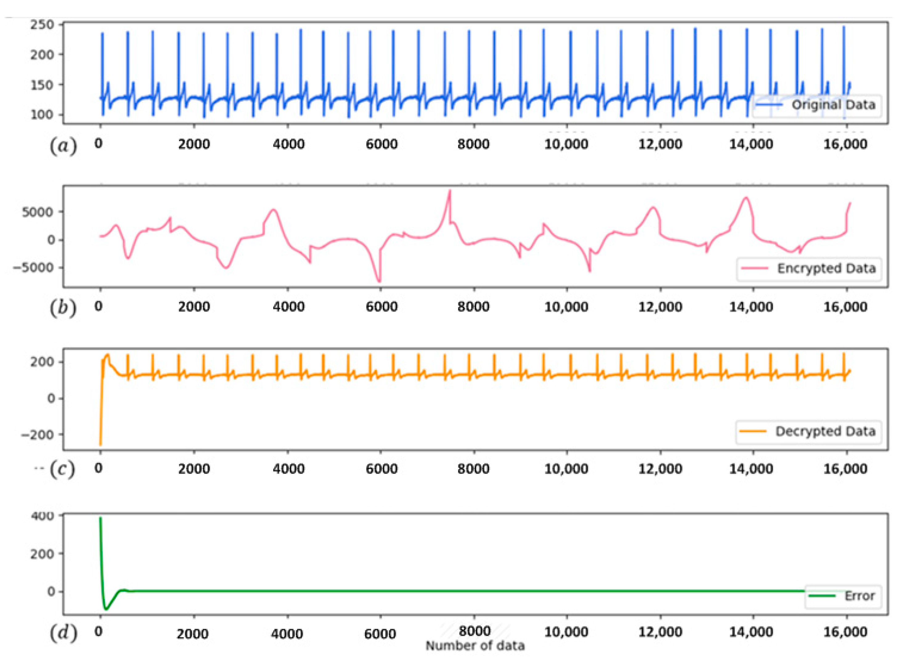
The original, encrypted, and decrypted bio-signals, as well as the error diagram of EMG, are shown in Figure 15, where the values of data range from 1 to 255. The second column in the figure shows that the original bio-signals have been encrypted and become a quite different system response from the original bio-signals. However, it takes some time for the chaotic systems to fully synchronize; thus, the fourth column shows that the error reaches 400 at the beginning, but after a few moments, approaches zero.
The third column shows that except for the part with a large error at the beginning, the plot is the same as that obtained from the original bio-signals after encryption and decryption; thus, we can confirm the completion of system synchronization and the accuracy of encryption and decryption.
The graphs of encryption, decryption, and error with ECG are shown in Figure 16, where the data points range from 93 to 246. The second column shows that the original ECG has been successfully encrypted, and as mentioned previously, substantial errors were noted in the third column.
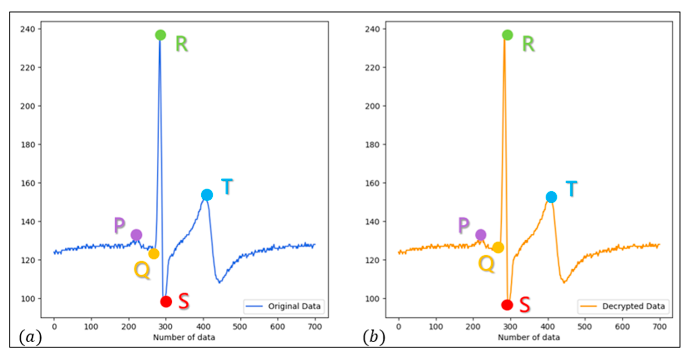
To confirm the data accuracy, the data of one wave are taken for verification. As shown in Figure 17, the waves remain the same before encryption and after decryption. Thus, we can confirm the completion of system synchronization and the accuracy of encryption and decryption with ECG.
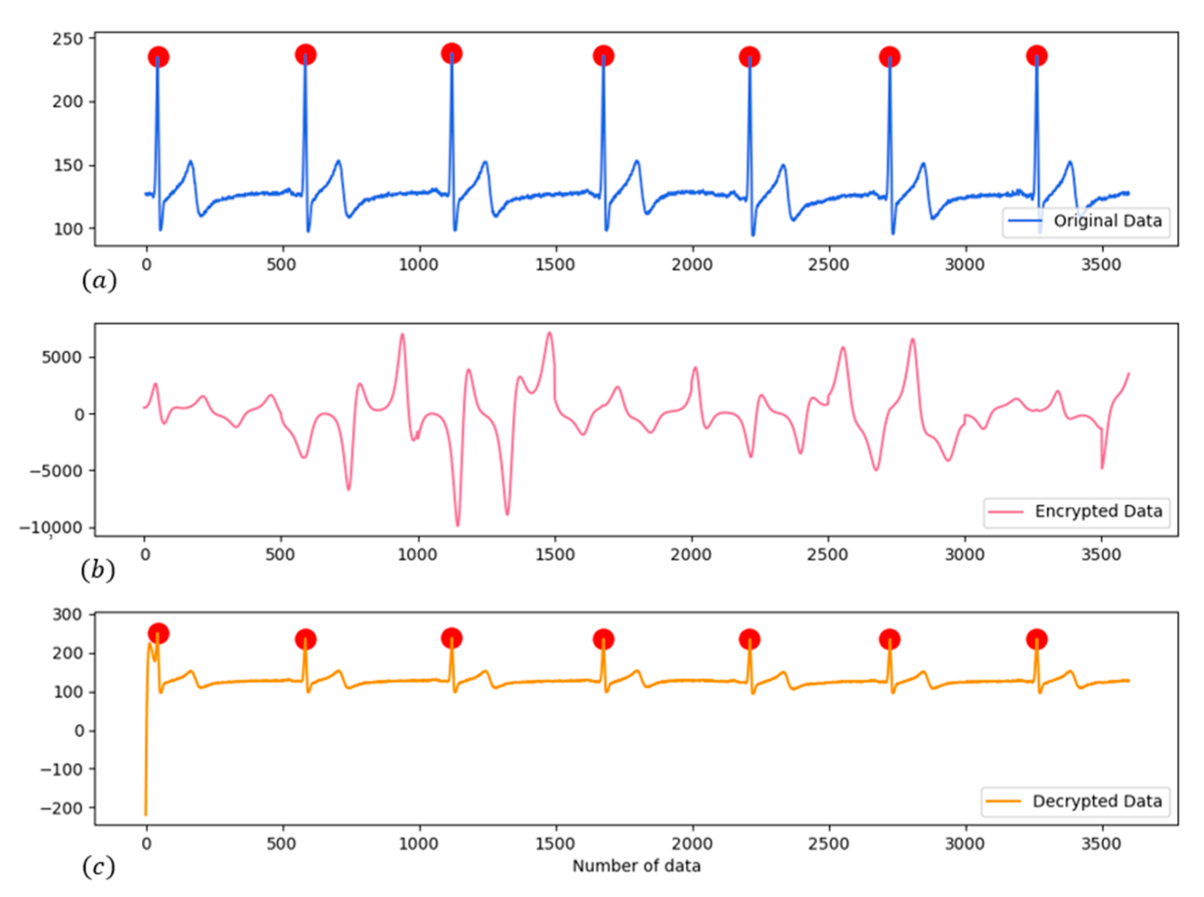
In case of the rate of heartbeats, we take the maximum value for every 500 data points, with a total of 3600 data points. Then, we take the average of the heartbeats from the maximum value of six sections. After the calculation, the heartrate [20] before encryption and after decryption remains constant at approximately 55.86 (beats/min), as shown in Figure 18.

5. Hardware Implementation

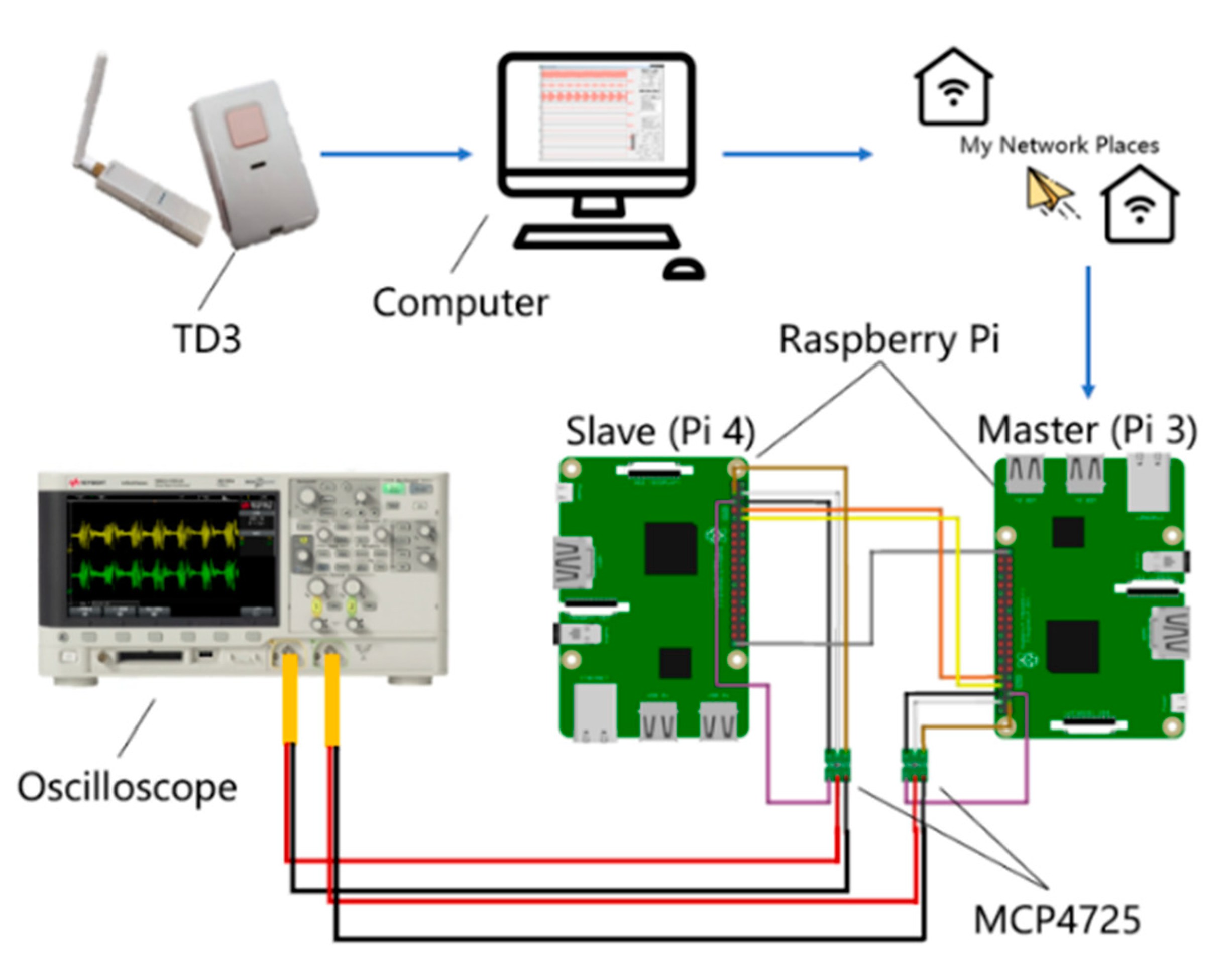
For the implementation, we use two Raspberry Pi computers to represent the master and slave. The architecture of the implementation and its photograph are shown in Figure 19 and Figure 20, respectively.

5.1. Implementation with Raspberry Pi

First, EMG and ECG data are collected using TD3, which indirectly saves the raw data into Raspberry Pi (master) through the computer with my network places. Then, the master executes the programming to read the raw data and completes the encryption, and finally, sends the encrypted information to the slave. The terminal of the master sends EMG with 31,136 data points for 44.515 s, and ECG with 16,080 data points for 22.936 s.
For information transmission, we use UART to transmit the encrypted bio-signals and x 2 n from the master to the slave. Before sending the information, Raspberry Pi (RPi) (master) sequentially packs x 2 n and the encrypted bio-signal into a data packet. Moreover, to avoid an excessive size of the transmitted data packet, x 2 n is approximated to only three digits after the decimal point.
After receiving the message and unpacking the data packet, the slave starts synchronizing the chaotic system and decrypting the bio-signals. The terminal of the slave receives EMG with 31,136 data points for 44.504 s, and ECG with 16,080 data points for 22.921 s. The synchronization time (error of the second states is less than 10 7 ) of the chaotic system is 0.462 s.
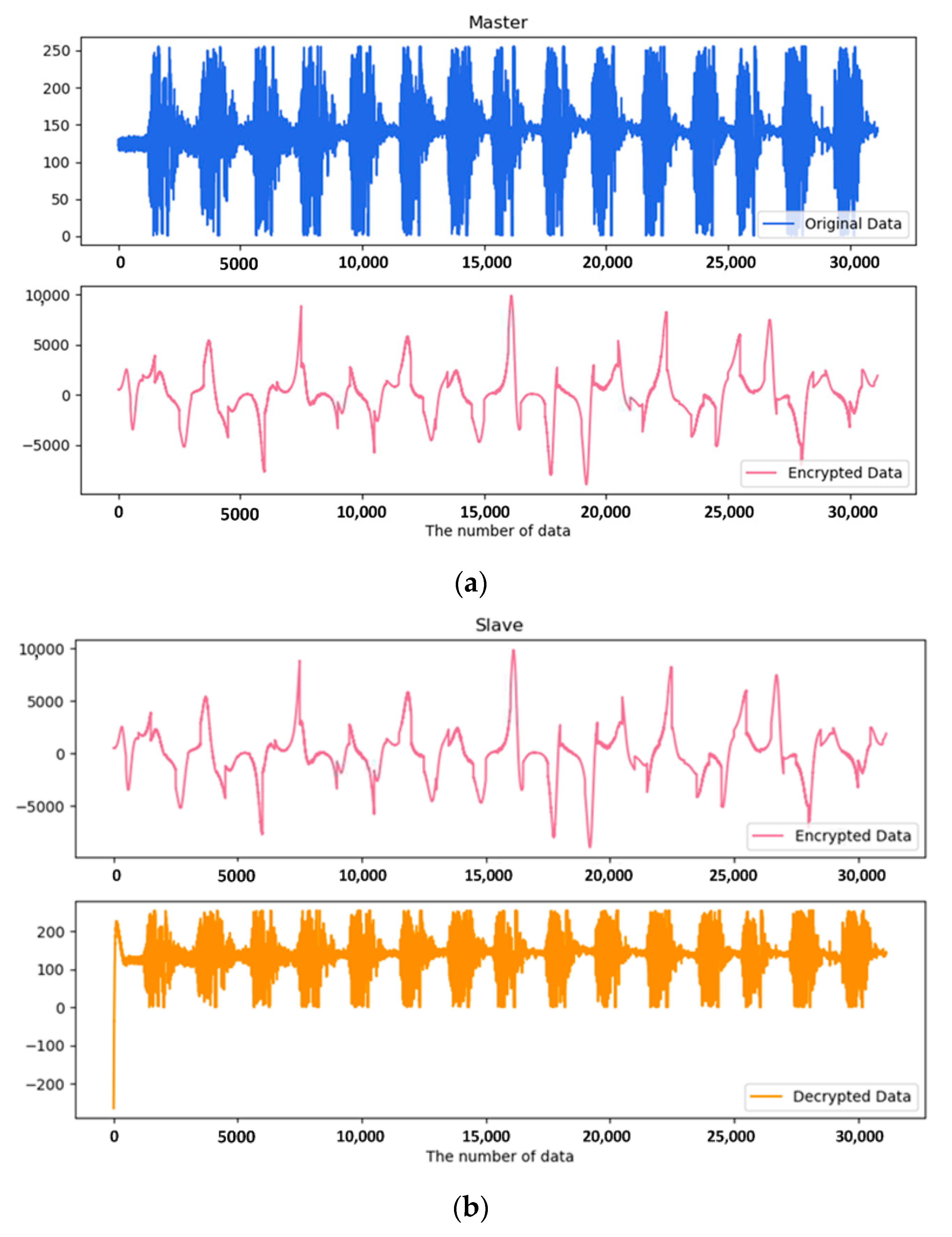
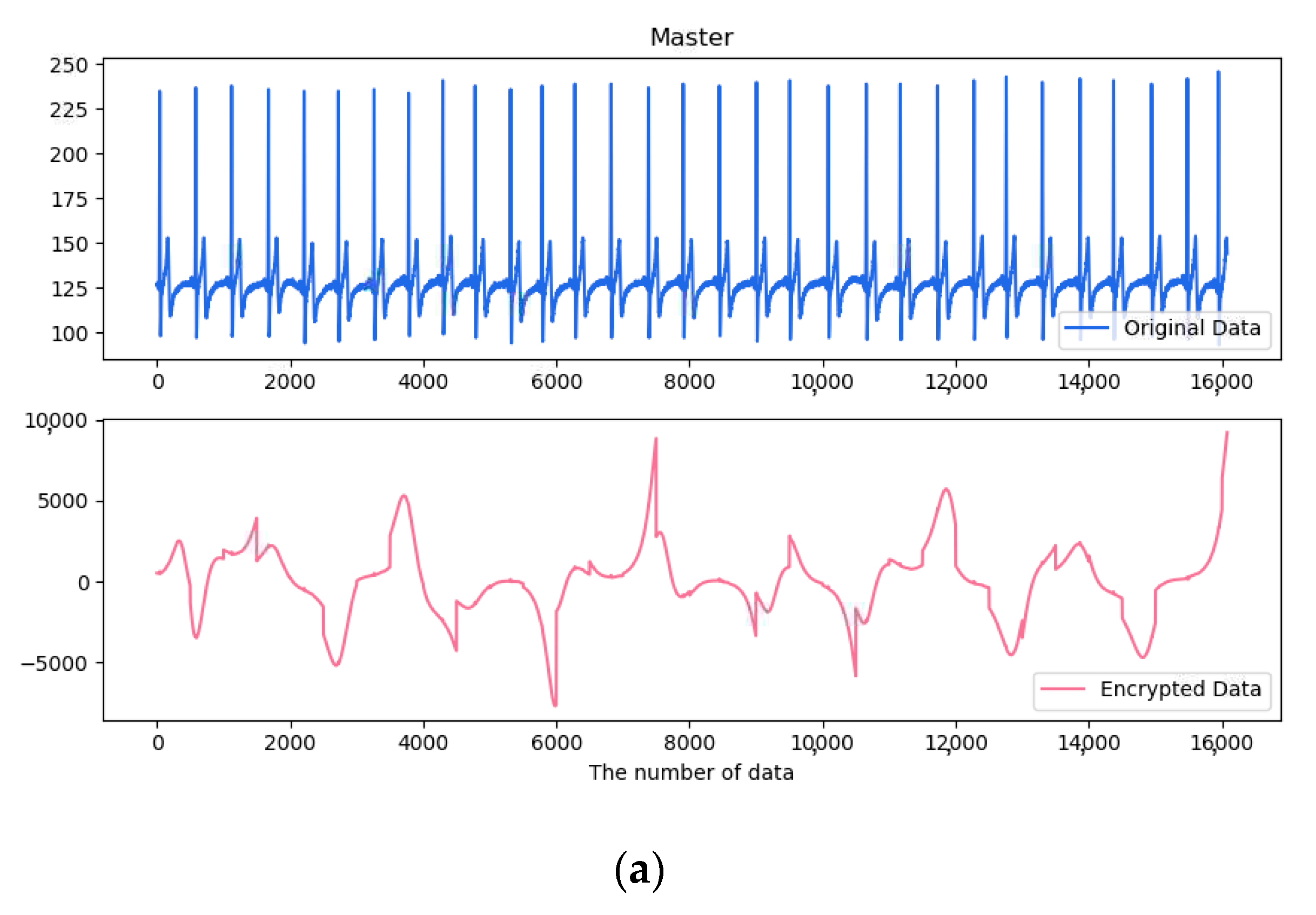
Figure 21 and Figure 22 show the bio-signal diagrams of EMG and ECG in the master, the original encrypted bio-signals, and the received and decrypted bio-signals in the slave. In the real system, irrespective of the EMG or ECG, the original bio-signals (blue) can be completely encrypted and decrypted (orange) from the following two figures. Moreover, it represents the two chaos systems, which can complete the synchronization and secretly transmit the biomedical information with the PD controller.

5.2. Result of Implementation

To carefully evaluate the accuracy of encryption and decryption, we use MCP4725 (INIKI Electronics Co. Ltd., Kaohsiung, Taiwan) to convert digital signals into analog signals from Raspberry Pi (RPi) to amplify the signals from 0 to 5 V. Thereafter, we use an oscilloscope to observe the results.
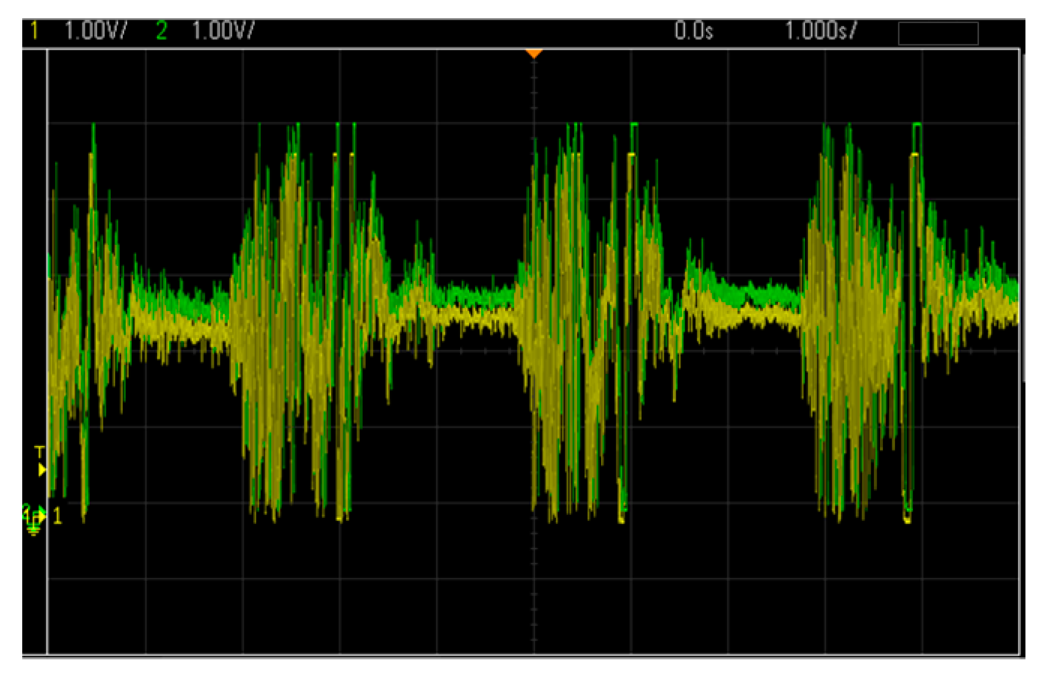
Figure 23 shows the signal diagram of x 1 n (yellow line) in the master and x 1 ¯ n (green line) in the slave, where the pink line indicates the difference between the two signals by subtraction. The unit of each signal is 500 mV/cell. The figure indicates that in the master and slave terminals, in addition to the error (pink line) with offset misalignment, the signals of the first states of the chaotic system have been successfully synchronized [21].
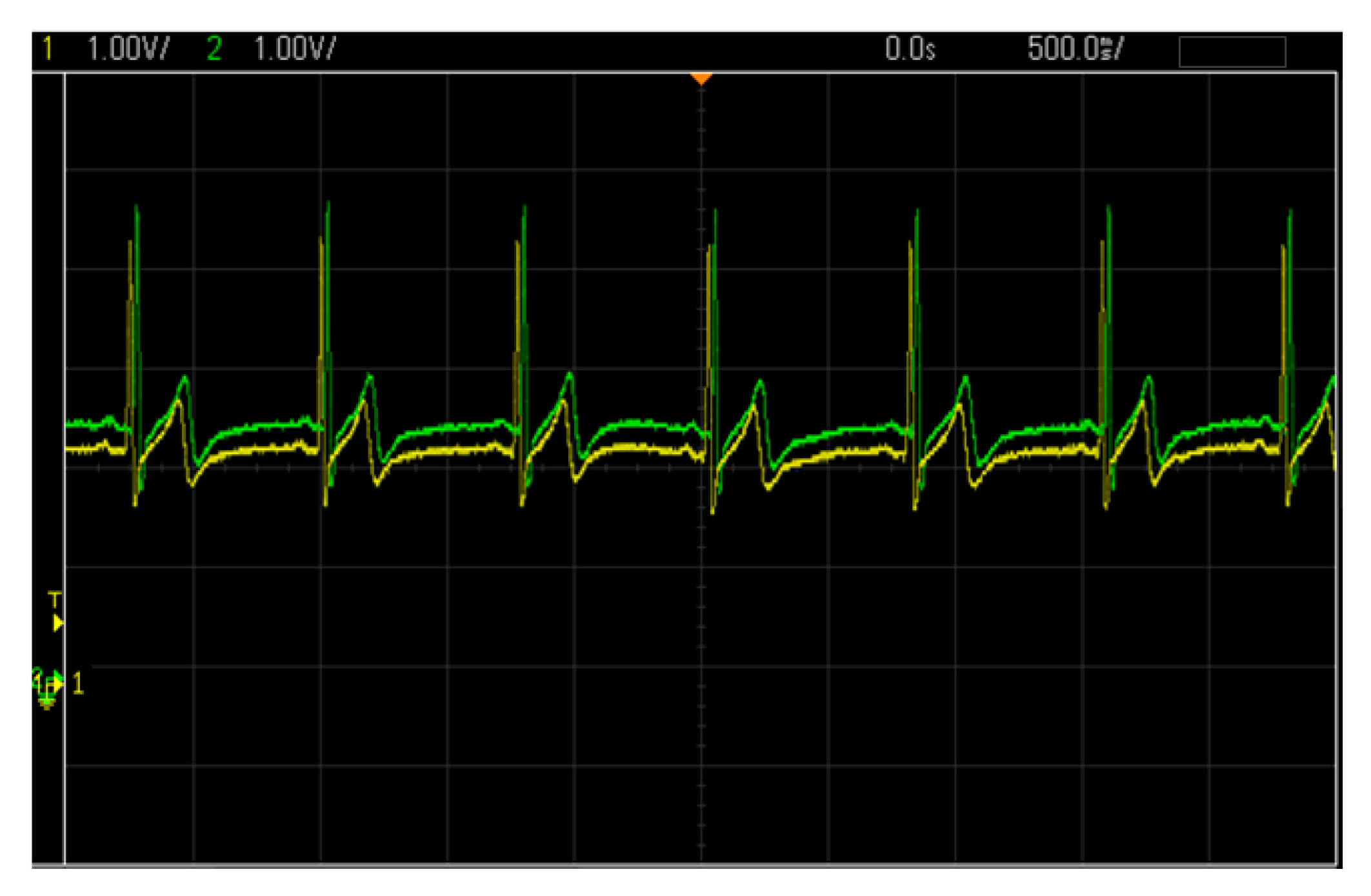
Figure 24 shows the EMG before encryption in the master and after decryption in the slave. The maximum and minimum values of the bio-signals are 0 and 5 V, respectively, and the unit is 1 V/cell. Figure 25 shows the ECG before encryption in the Master and after decryption in the Slave. The maximum and minimum bio-signals are 2 V and 4.5 V, respectively, with unit of 1 V/cell. The figure indicates that the bio-signals before encryption and after decryption remain the same, except for the offset misalignment of the error.
As mentioned previously in Figure 14, we take one state from each chaotic system, and as a result, draw the same attractors from the master and slave. Here, we follow the steps shown in Figure 16 and take x 3 n and x 1 ¯ n from the master and slave, respectively. Then, the result is displayed on an oscilloscope, as shown in Figure 26.

6. Conclusions

The results obtained in this study verify the fact that the characteristics of the biomedical information after encryption and decryption remain the same, which means that the two chaotic systems are indeed synchronized and generate the same states, so that the biomedical information remains correct.
During the implementation, we use UART to communicate between the two chaotic systems and synchronize them with the proportional–derivative controller. The experimental result indicates that the master chaotic system successfully transmits the encrypted biomedical information to the other side by using the slave chaotic system. Moreover, we can obtain the same biomedical information after decryption.
In summary, we verify that both biomedical information, EMG and ECG bio-signals, can be transmitted securely after encryption, and after receiving the data, can be decrypted correctly. Thus, we can achieve our goal based on the chaotic system, with a synchronization controller applied to the security of the biomedical information.

Author Contributions

Conceptualization, T.-L.L.; methodology, T.-L.L. and Y.-Y.H.; software, C.-Y.P. and Y.-Y.H.; validation, Y.-Y.H. and H.-C.C.; writing—original draft preparation, C.-Y.P., H.-C.C. and Y.-Y.H.; writing—review and editing, T.-L.L., H.-C.C., and Y.-Y.H.; supervision, T.-L.L.; funding acquisition, T.-L.L., H.-C.C. and Y.-Y.H. All authors have read and agreed to the published version of the manuscript.

Funding

This work was financially supported by the Ministry of Science and Technology, Taiwan, under grant MOST 108-2221-E-006 -214 -MY2, 108-2221-E-992-094-, and 108-2637-E-241-002.

Data Availability Statement

Data sharing is not applicable to this article.

Conflicts of Interest

The authors declare no conflict of interest.

References

  1. Somani, U.; Lakhani, K.; Mundra, M. Implementing Digital Signature with RSA Encryption Algorithm to Enhance the Data Security of Cloud in Cloud Computing. In Proceedings of the 2010 First International Conference On Parallel, Distributed and Grid Computing (PDGC 2010), Solan, India, 28–30 October 2010. [Google Scholar]
  2. Ali, D.S.; Alwan, N.A.; Al-Saidi, N.M.G. Image encryption based on highly sensitive chaotic system. In AIP Conference Proceedings; AIP Publishing LLC: New York, NY, USA, 2019; Volume 2183. [Google Scholar]
  3. Chen, H.-C.; Chang, G.-F.; Yan, J.-J.; Liao, T.F. EP-based PID control design for chaotic synchronization with application in secure communication. Expert Syst. Appl. 2008, 34, 1167–1177. [Google Scholar] [CrossRef]
  4. Peyghami, S.; Blaabjerg, F. Availab. Modeling in Power Converters Considering Components Aging. IEEE Trans. Energy Convers. 2020, 35, 1981–1984. [Google Scholar] [CrossRef]
  5. De la Roca, L.; Peterson, J.; Pereira, M.; Cunha, A., Jr. Control of Chaos via OGY Method on a Bistable Energy Harvester. In Proceedings of the 25th ABCM International Congress on Mechanical Engineering (COBEM 2019), Uberlândia, Brazil, 20–25 October 2019. [Google Scholar]
  6. Pecora, L.M.; Carroll, T.L. Synchronization in chaotic systems. Phys. Rev. Lett. 1990, 64, 821–824. [Google Scholar] [CrossRef] [PubMed]
  7. ATaher Azar, A. Sundarapandian Vaidyanathan Advances in Chaos Theory and Intelligent Control; Springer International Publishing AG: Cham, Switzerland, 2016. [Google Scholar]
  8. Wu, J.; Liao, X.; Yang, B. Image encryption using 2D Hénon-Sine map and DNA approach. Signal Process. 2018, 153, 11–23. [Google Scholar] [CrossRef]
  9. Jaeger, H.; Haas, H. Harnessing Nonlinearity: Predicting Chaotic Systems and Saving Energy in Wireless Communication. Science 2004, 304, 5667. [Google Scholar] [CrossRef] [PubMed] [Green Version]
  10. Shah, S.A.; Ahmad, J.; Masood, F.; Shah, S.Y.; Pervaiz, H.; Taylor, W.; Ali Imran, M.; Abbasi, Q.H. Privacy-Preserving Wandering BehaviorSensing in Dementia Patients Using ModifiedLogistic and Dynamic Newton Leipnik Maps. IEEE Sens. J. 2021, 21, 3. [Google Scholar]
  11. Qayyum, A.; Ahmad, J.; Boulila, W.; Rubaiee, S.; Arshad; Masood, F.; Khan, F.; Buchanan, W.J. Chaos-Based Confusion and Diffusion of Image Pixels Using Dynamic Substitution. IEEE Access 2020, 8, 140876–140895. [Google Scholar] [CrossRef]
  12. AbdelAty, A.M.; Azar, A.T.; Vaidyanathan, S.; Ouannas, A.; Radwan, A.G. Chapter 14—Applications of Continuous-time Fractional Order Chaotic Systems. In Mathematical Techniques of Fractional Order Systems; Elsevier: Amsterdam, The Netherlands, 2018; pp. 409–449. [Google Scholar]
  13. Leonov, G.A.; Kuznetsov, N.V. On differences and similarities in the analysis of Lorenz, Chen, and Lu systems. Appl. Math. Comput. 2015, 256, 334–343. [Google Scholar] [CrossRef] [Green Version]
  14. Bansal, J.C. Particle Swarm Optimization. In Evolutionary and Swarm Intelligence Algorithms, Studies in Computational Intelligence; Springer International Publishing AG: Cham, Switzerland, 2018; Volume 779, pp. 11–23. [Google Scholar]
  15. AL-Ziarjawey, H.A.J.; Çankaya, I. Heart Rate Monitoring and PQRST Detection Based on Graphical User Interface with Matlab. Int. J. Inf. Electron. Eng. 2015, 5, 311–312. [Google Scholar] [CrossRef] [Green Version]
  16. Rukhin, A.; Soto, J.; Nechvatal, J.; Smid, M.; Barker, E.; Leigh, S.; Levenson, M.; Vangel, M.; Banks, D.; Heckert, A.; et al. A Statistical Test Suite for Random and Pseudorandom Number Generators for Cryptographic Applications; Report for National Institute of Standards and Technology; U.S. Department of Commerce: Gaithersburg, MD, USA, September 2010.
  17. Corinto, F.; Krulikovskyi, O.V.; Haliuk, S.D. Memristor-Based Chaotic Circuit for Pseudo-Random Sequence Generators. In Proceedings of the 2016 18th Mediterranean Electrotechnical Conference (MELECON), Lemesos, Cyprus, 18–20 April 2016. [Google Scholar]
  18. Sharma, M.; Agarwal, N.; Reddy, S. Design and Development of Daughter Board for USB-UART Communication between Raspberry Pi and PC. In Proceedings of the International Conference on Computing, Communication & Automation, Noida, India, 15–16 May 2015. [Google Scholar]
  19. Zirkohia, M.M.; khorashadizadeh, S. Paperchaos synchronization using higher-order adaptive PID controllerMajid. AEU Int. J. Electron. Commun. 2018, 94, 157–167. [Google Scholar] [CrossRef]
  20. De Chazal, P.; Reilly, R.B. Automatic Classification of ECG Beats Using Waveform Shape and Heart Beat Interval Features. In Proceedings of the 2003 IEEE International Conference on Acoustics, Speech, and Signal Processing (ICASSP ‘03), Hong Kong, China, 6–10 April 2003. [Google Scholar]
  21. Zade, M.C. Control the Chaotic Rikitake System by PID Controller. SSRG Int. J. Electr. Electron. Eng. (SSRG-IJEEE) 2015, 2, 1–4. [Google Scholar]
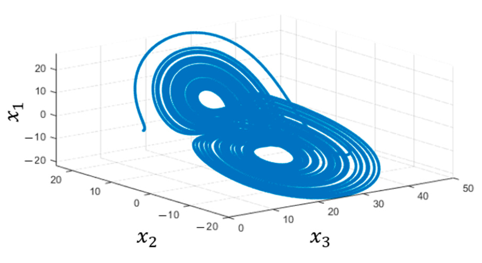
Figure 1. Strange attractor in master.
Electronics 10 00359 g001
Figure 2. Strange attractor in slave.
Electronics 10 00359 g002
Figure 3. (a) Chaotic systems without a proportional-derivative (PD) controller; (b) The error of the chaotic systems without a PD controller.
Electronics 10 00359 g003aElectronics 10 00359 g003b
Figure 4. Response of X (Kp, Ki, Kd) with Particle Swarm Optimization (PSO).
Electronics 10 00359 g004
Figure 5. Response of the error with PSO.
Electronics 10 00359 g005
Figure 6. (a) Chaotic systems with PD controller; (b) The error of the chaotic systems with PD controller.
Electronics 10 00359 g006
Figure 7. Electrocardiography.
Electronics 10 00359 g007
Figure 8. The secure biomedical system architecture.
Electronics 10 00359 g008
Figure 9. Architecture of the system.
Electronics 10 00359 g009
Figure 10. Wireless multi-channel physiological signal recording system.
Electronics 10 00359 g010
Figure 11. Result of Electrocardiography (ECG).
Electronics 10 00359 g011
Figure 12. Action of measuring Electromyography (EMG).
Electronics 10 00359 g012
Figure 13. Result of EMG.
Electronics 10 00359 g013
Figure 14. Simulation of the attractors. (a) x1 to y1; (b) x2 to y1; (c) x3 to y1; (d) x1 to y2; (e) x2 to y2; (f) x3 to y2; (g) x1 to y3; (h) x2 to y3; (i) x3 to y3.
Electronics 10 00359 g014
Figure 15. Simulation results of EMG. (a) The original data; (b) Encrypted data; (c) Decrypted data; (d) The error between the original data and decryted data.
Electronics 10 00359 g015
Figure 16. Simulation results of ECG. (a) The original data; (b) Encrypted data; (c) Decrypted data; (d) The error between the original data and decryted data.
Electronics 10 00359 g016
Figure 17. Simulation results of ECG. (a) The original data; (b) Decrypted data.
Electronics 10 00359 g017
Figure 18. Simulation of heart rate. (a) The original data; (b) Encrypted data; (c) Decrypted data.
Electronics 10 00359 g018
Figure 19. Architecture of the implementation.
Electronics 10 00359 g019
Figure 20. Implementation of the chaos systems.
Electronics 10 00359 g020
Figure 21. Implementation of EMG with Raspberry Pi (RPi). (a) The data in the Master; (b) The data in the Slave.
Electronics 10 00359 g021
Figure 22. Implementation of ECG with RPi. (a) The data in the Master; (b) The data in the Slave.
Electronics 10 00359 g022aElectronics 10 00359 g022b
Figure 23. Variables x 2 n and x 2 ¯ n with Raspberry Pi.
Electronics 10 00359 g023
Figure 24. EMG with Raspberry Pi.
Electronics 10 00359 g024
Figure 25. ECG with Raspberry Pi.
Electronics 10 00359 g025
Figure 26. Strange attractor with x 3 n and x 1 ¯ n .
Electronics 10 00359 g026
Table 1. The result of the National Institute of Standards and Technology (NIST) test.
NIST Testp-Value
Frequency (Monobit)0.082918
Frequency within a Block0.757670
Runs0.370782
Longest Run of Ones in a Block0.225761
Binary Matrix Rank0.555467
Discrete Fourier Transform (Spectral)0.897775
Non-overlapping Template Matching0.484386
Overlapping Template Matching0.260229
Universal Statistical0.881887
Linear Complexity0.518763
Serial0.725205
Approximate Entropy0.626338
Cumulative Sums (Cusum)0.104932
Random Excursions0.416972
Random Excursions Variant0.552373
SUM0.497431
Publisher’s Note: MDPI stays neutral with regard to jurisdictional claims in published maps and institutional affiliations.