
Temperature Control Concept for Parallel IGBT Operation


Abstract
:1. Introduction
2. Assembled IGBT Test Board
3. Developed Algorithms
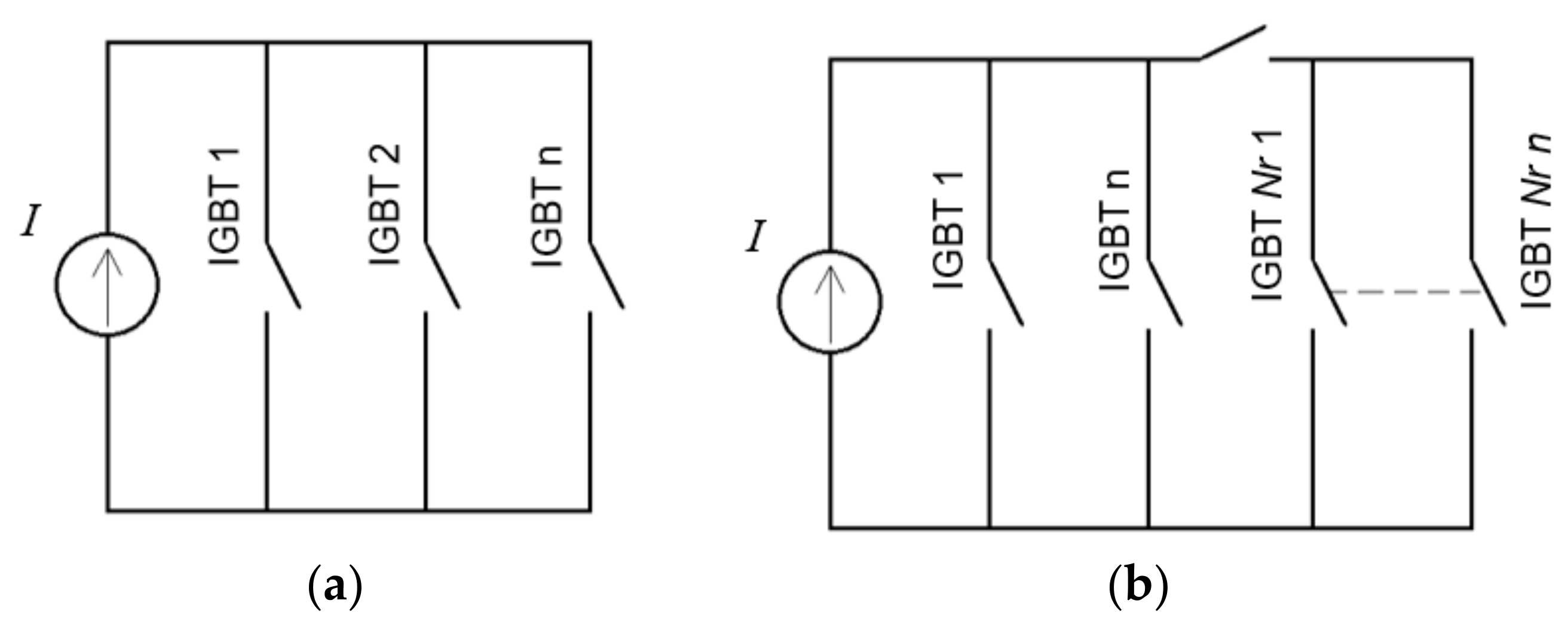
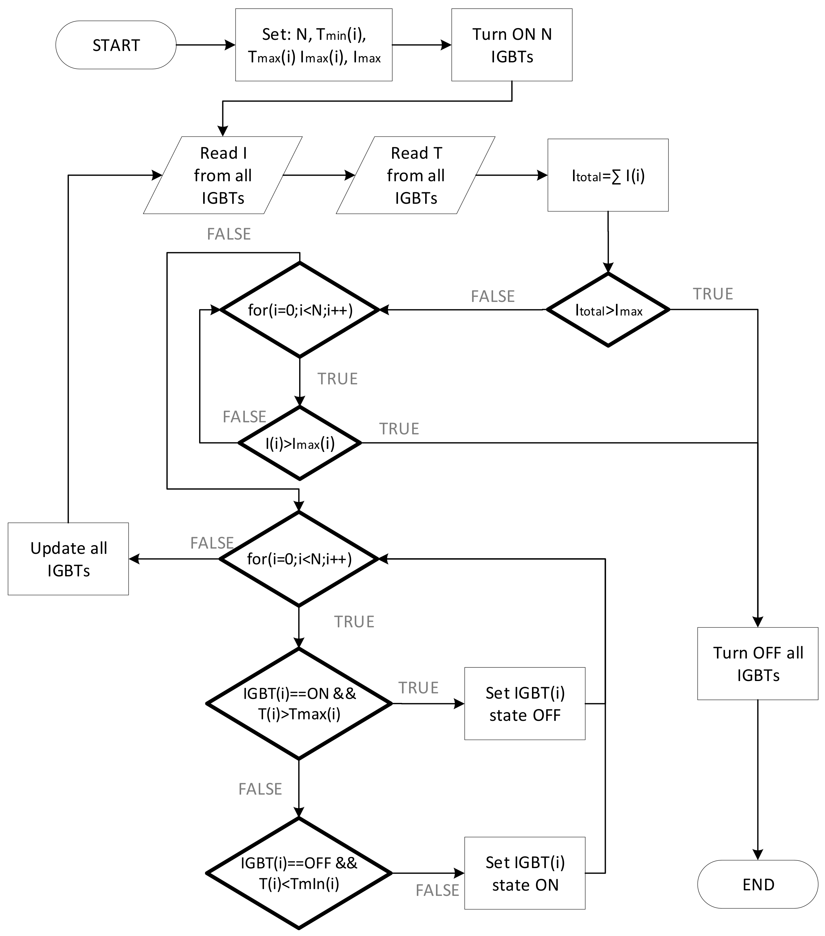
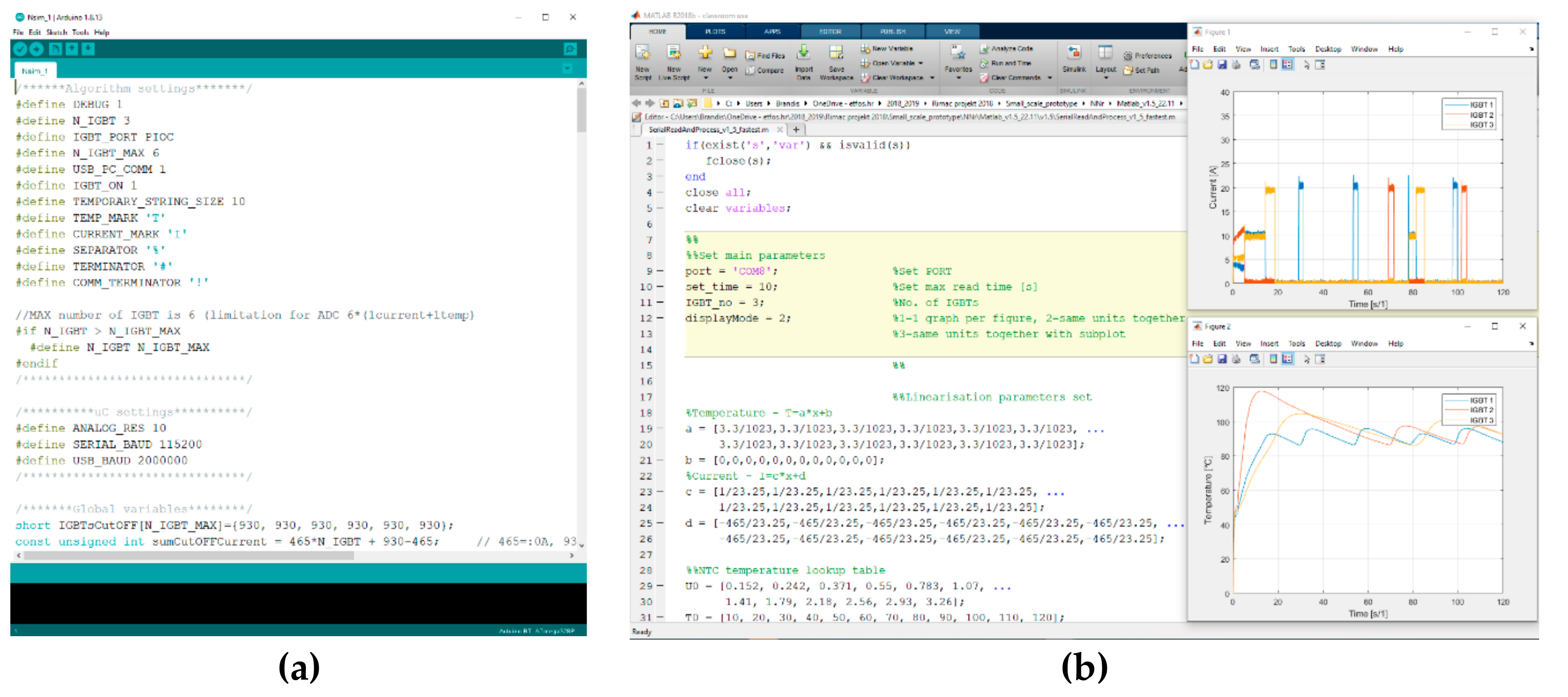
3.1. Nsim Algorithm
- N—number of engaged IGBTs;
- T2(i), i = 1, 2, …, N—upper temperature threshold or the maximum temperature of the IGBT when the IGBT is disabled;
- T1(i), i = 1, 2, …, N—lower temperature threshold or the temperature at which the IGBT is engaged again after cooling down from T2(i);
- Imax—sum of all IGBT currents or the value of the current at which the system shuts down all IGBTs and the test ends;
- Imax(i), i = 1, 2, …, N—maximum current of an individual IGBT or the value of the current at which all IGBTs are disabled and the test ends.
3.2. NNr Algorithm
- N—number of the main engaged IGBTs;
- Nr—number of redundant IGBTs.
4. Experimental Results
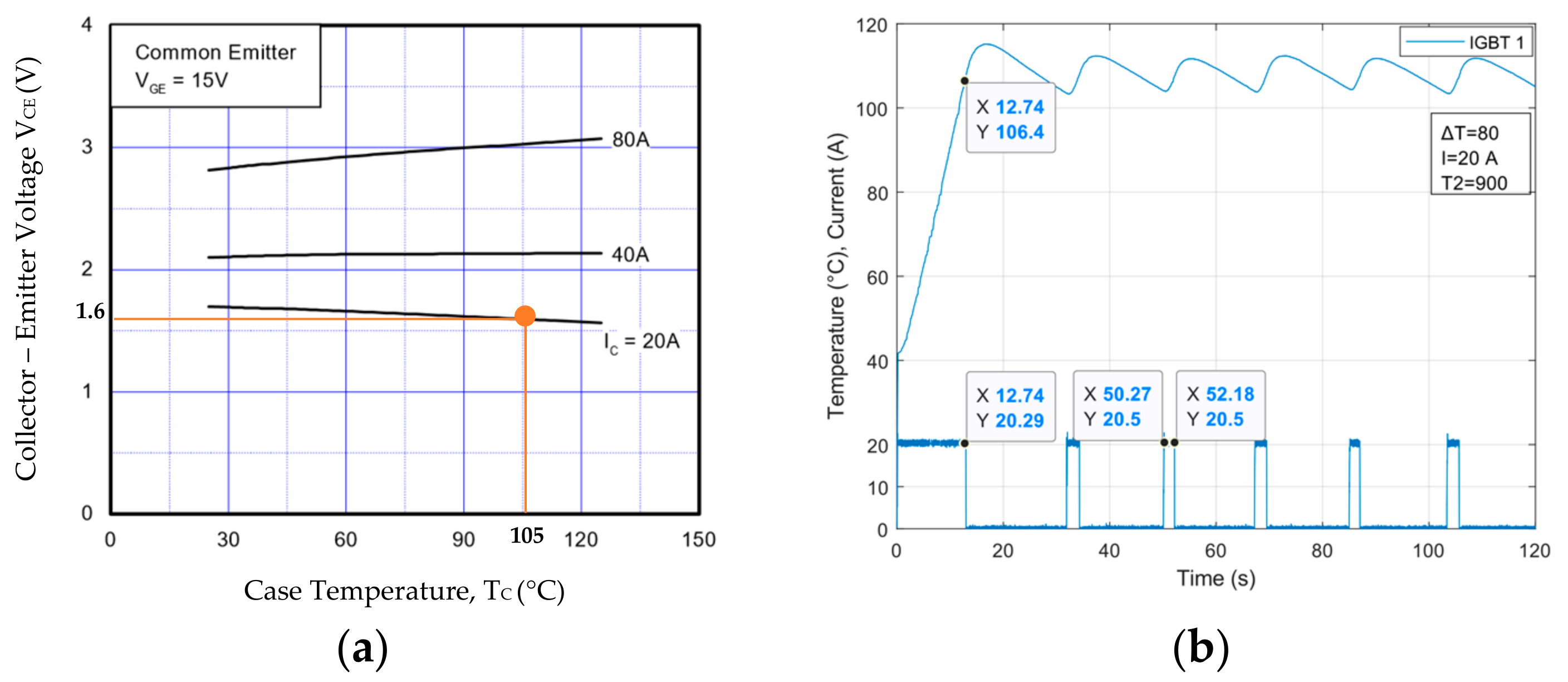
4.1. IGBT Current-Temperature Characteristic
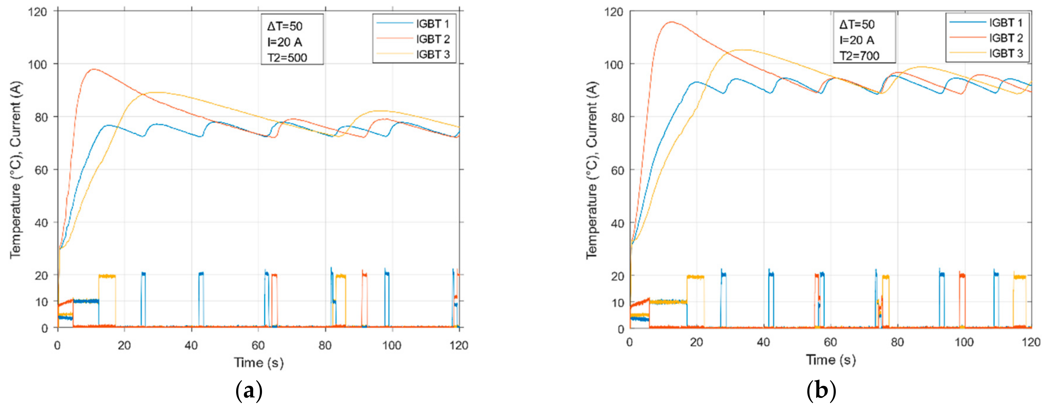
4.2. Measurements on Nsim Algorithm
4.3. Measurements on NNr Algorithm
4.4. Nsim and NNr Algorithm Comparison
5. Conclusions
Supplementary Materials
Author Contributions
Funding
Data Availability Statement
Conflicts of Interest
References
- Rodrigues, E.M.G.; Godina, R.; Pouresmaeil, E. Industrial Applications of Power Electronics. Electronics 2020, 9, 1534. [Google Scholar] [CrossRef]
- Nguyen, M.-K. Power Converters in Power Electronics: Current Research Trends. Electronics 2020, 9, 654. [Google Scholar] [CrossRef]
- Hermansson, W.; Chimento, F.; Jonsson, T. Robustness Evaluation of High Voltage Press Pack IGBT Modules in Enhanced Short Circuit Test. In Proceedings of the IEEE Energy Conversion Congress and Exposition, Atlanta, GA, USA, 12–16 September 2010. [Google Scholar]
- Feng, L.; Gou, R.; Zhuo, F.; Yang, X.; Zhang, F. Development of a 10 kV Solid-State DC Circuit Breaker Based on Press-Pack IGBT for VSC-HVDC System. In Proceedings of the 2016 IEEE 8th International Power Electronics and Motion Control Conference (IPEMC-ECCE Asia), Hefei, China, 22–26 May 2016; pp. 2371–2377. [Google Scholar]
- Brandelero, J.; Ewanchuk, J.; Mollov, S. Selective Gate Driving in Intelligent Power Modules. IEEE Trans. Power Electron. 2020, 36, 13. [Google Scholar] [CrossRef]
- Wang, X.; Qing, H.; Huang, P.; Zhang, C. Modeling and Stability Analysis of Parallel Inverters in Island Microgrid. Electronics 2020, 9, 463. [Google Scholar] [CrossRef] [Green Version]
- Chen, N.; Chimento, F.; Nawaz, M.; Wang, L. Dynamic Characterization of Parallel-Connected High-Power IGBT Modules. In Proceedings of the 2013 IEEE Energy Conversion Congress and Exposition, Denver, CO, USA, 15–19 September 2013; pp. 4263–4269. [Google Scholar]
- Alvarez, R.; Fink, K.; Bernet, S. Simulation and Experimental Investigation of Parallel Connected IGBTs. In Proceedings of the 2010 IEEE International Conference on Industrial Technology, Vi a del Mar, Chile, 14–17 March 2010; pp. 824–831. [Google Scholar]
- Schlapbach, U. Dynamic Paralleling Problems in IGBT Module Construction and Application. In Proceedings of the 6th International Conference on Integrated Power Electronics Systems, Nuremberg, Germany, 16–18 March 2010; pp. 1–7. [Google Scholar]
- Jadhav, V.; Zhou, Y.; Jansen, U. Analysis of Different IGBT Gate Driver Strategies Influencing Dynamic Paralleling Performance. In Proceedings of the PCIM Asia 2016; International Exhibition and Conference for Power Electronics, Intelligent Motion, Renewable Energy and Energy Management, Shanghai, China, 28–30 June 2016; pp. 1–9. [Google Scholar]
- Spang, M.; Katzenberger, G. Current Sharing between Parallel IGBTs in Power Modules during Short Circuit with Unsymmetrically Connected Load. In Proceedings of the 2016 18th European Conference on Power Electronics and Applications (EPE’16 ECCE Europe), Germany, Karlsruhe, 5–9 September 2016; pp. 1–9. [Google Scholar]
- Robin, S. Influences of Gate-Circuit and Parasitic Inductances on Turn-Off Current Imbalances of Paralleled IGBTs Due to Differences in Their Switching Behaviour. In Proceedings of the 2018 20th European Conference on Power Electronics and Applications (EPE’18 ECCE Europe), Riga, Latvia, 17–21 September 2018; pp. 1–10. [Google Scholar]
- Su, H.; Wang, L.; Zhao, F.; Wang, L.; Luo, J. A Novel Electrical Evaluation Approach for Inhomogeneous Current Distribution in Parallel-Connected IGBT Modules. In Proceedings of the 2018 IEEE International Symposium on the Physical and Failure Analysis of Integrated Circuits (IPFA), Singapore, 16–19 July 2018; pp. 1–4. [Google Scholar]
- Zhu, N.; Chen, M.; Yan, R.; Mantooth, A.; Xu, D. Die Current Balancing of a Press-Pack SiC MOSFET. In Proceedings of the 2018 IEEE Energy Conversion Congress and Exposition (ECCE), Portland, OR, USA, 23–27 September 2018; pp. 5824–5830. [Google Scholar]
- Yang, J.; Che, Y.; Ran, L. Evaluation of Frequency and Temperature Dependence of Power Losses Difference in Parallel IGBTs. IEEE Access 2020, 8, 104074–104084. [Google Scholar] [CrossRef]
- Li, H.; Zhou, W.; Wang, X.; Munk-Nielsen, S.; Li, D.; Wang, Y. Influence of Paralleling Dies and Paralleling Half-Bridges on Transient Current Distribution in Multichip Power Modules. IEEE Trans. Power Electron. 2018, 33, 6483–6487. [Google Scholar] [CrossRef]
- Chen, Y.; Zhuo, F.; Pan, W.; Zhang, F.; Feng, L. A Novel Active Gate Driver for Static and Dynamic Current Balancing of Parallel-Connected IGBTs. In Proceedings of the 2017 IEEE Applied Power Electronics Conference and Exposition (APEC), Tampa, FL, USA, 26–30 March 2017; pp. 795–799. [Google Scholar]
- Sasaki, M.; Nishio, H.; Ng, W.T. Dynamic Gate Resistance Control for Current Balancing in Parallel Connected IGBTs. In Proceedings of the 2013 Twenty-Eighth Annual IEEE Applied Power Electronics Conference and Exposition (APEC), Long Beach, CA, USA, 17–21 March 2013; pp. 244–249. [Google Scholar]
- Shammas, N.Y.A.; Withanage, R.; Chamund, D. Review of Series and Parallel Connection of IGBTs. IEE Proc. Circuits Devices Syst. 2006, 153, 34. [Google Scholar] [CrossRef]
- Alvarez, R.; Bernet, S. A New Delay Time Compensation Principle for Parallel Connected IGBTs. In Proceedings of the 2011 IEEE Energy Conversion Congress and Exposition, Phoenix, AZ, USA, 17–21 September 2011; pp. 3000–3007. [Google Scholar]
- Chen, Y.; Zhuo, F.; Zhang, F.; Pan, W.; Yang, Y. A Novel Method for Current Balancing between Parallel-Connected IGBTs. In Proceedings of the 2016 18th European Conference on Power Electronics and Applications (EPE’16 ECCE Europe), Karlsruhe, Germany, 5–9 September 2016; pp. 1–8. [Google Scholar]
- Du, X.; Zhuo, F.; Sun, H.; Yi, H.; Zhu, Y. An Integrated Voltage and Current Balancing Strategy of Series-Parallel Connected IGBTs. In Proceedings of the 2018 International Power Electronics Conference (IPEC-Niigata 2018 -ECCE Asia), Niigata, Japan, 20–24 May 2018; pp. 2780–2784. [Google Scholar]
- Zeng, X.; Li, Z.; Wan, J.; Zhang, J.; Ren, M.; Gao, W.; Li, Z.; Zhang, B. Embedded Hardware Artificial Neural Network Control for Global and Real-Time Imbalance Current Suppression of Parallel Connected IGBTs. IEEE Trans. Ind. Electron. 2020, 67, 2186–2196. [Google Scholar] [CrossRef]
- Tripathi, R.N.; Tsukuda, M.; Omura, I. Peak Minimisation Based Gate Delay Compensation for Active Current Balancing of Parallel IGBT System. Microelectron. Reliab. 2019, 100–101. [Google Scholar] [CrossRef]
- Beushausen, S.; Herzog, F.; Doncker, R.W.D. GaN-Based Active Gate-Drive Unit With Closed-Loop Du/Dt-Control for IGBTs in Medium-Voltage Applications. In Proceedings of the PCIM Europe Digital Days 2020; International Exhibition and Conference for Power Electronics, Intelligent Motion, Renewable Energy and Energy Management, Germany, 7–8 July 2020; pp. 1–8. [Google Scholar]
- Li, L.-L.; Wang, P.-C.; Wang, C.-H. Lifetime Prediction Model for Electric Vehicle IGBT Modules under Driving Conditions. J. Chin. Inst. Eng. 2018, 41, 308–316. [Google Scholar] [CrossRef]
- Wang, C.; He, Y.; Wang, C.; Li, L.; Wu, X. Multi-Chip IGBT Module Failure Monitoring Based on Module Transconductance with Temperature Calibration. Electronics 2020, 9, 1559. [Google Scholar] [CrossRef]
- Microchip Atmel-11057-32-Bit-Cortex-M3-Microcontroller-SAM3X-SAM3A Datasheet. Available online: https://ww1.microchip.com/downloads/en/DeviceDoc/Atmel-11057-32-bit-Cortex-M3-Microcontroller-SAM3X-SAM3A_Datasheet.pdf (accessed on 13 July 2020).
- Fairchild SGH80N60UFD. Available online: https://www.alldatasheet.com/datasheet-pdf/pdf/54585/FAIRCHILD/SGH80N60UFD.html (accessed on 20 January 2021).
- Precision Glass Encapsulated NTC Thermistors Datasheet. Available online: https://www.cantherm.com/wp-content/uploads/2017/05/cantherm_mf58_1.pdf (accessed on 10 July 2020).
- NI Multisim. Available online: https://www.ni.com/en-rs/support/downloads/software-products/download.multisim.html#312060 (accessed on 20 January 2020).
- Yu, C.; Zhou, W.-C.; Sun, B.; Zhou, H.-X. Study on NTC Thermistor Characteristic Curve Fitting Methods. In Proceedings of the 2011 International Conference on Computer Science and Network Technology, Harbin, China, 24–26 December 2011; pp. 2209–2213. [Google Scholar]


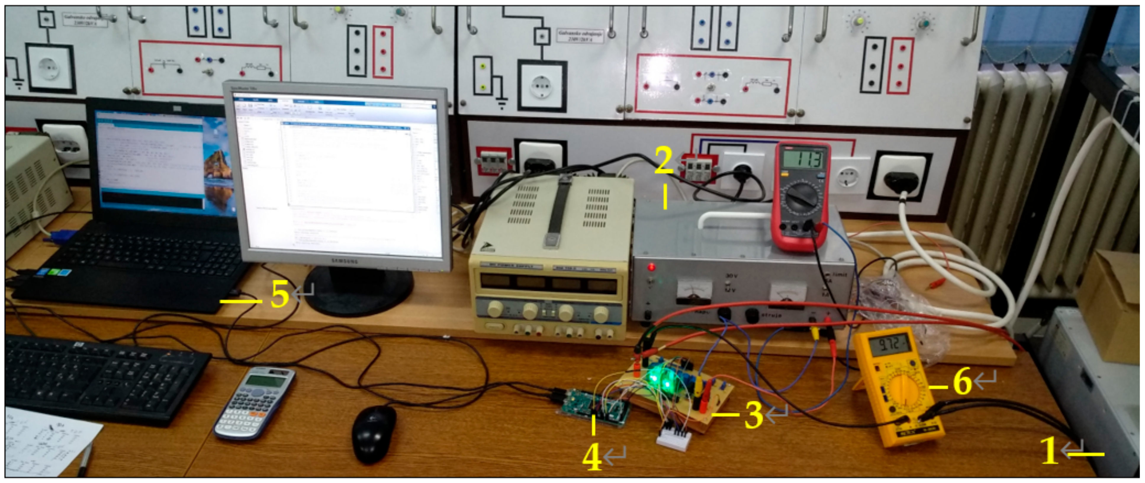
| Mark (Figure 2) | Item | Description |
|---|---|---|
| 1 | Transistor | Fairchild SGH80N60UFD |
| 2 | Thermistor | Cantherm NTC MF58 |
| 3 | Current Transducer | LEM LTS 25-NP |
| 4 | Driver | Microchip TC4420 |
| 5 | Voltage regulator | Texas Instruments LM7805 *1 |
| 6 | Calibration circuit | Trimmers, capacitors, resistors |
| 7 | LED | Vishay TLHG6400 *2 |
| 8 | Connections | Banana socket |
| 9, 10, 11 | Connections | Male Header |
| 12 | Board | Single-sided |
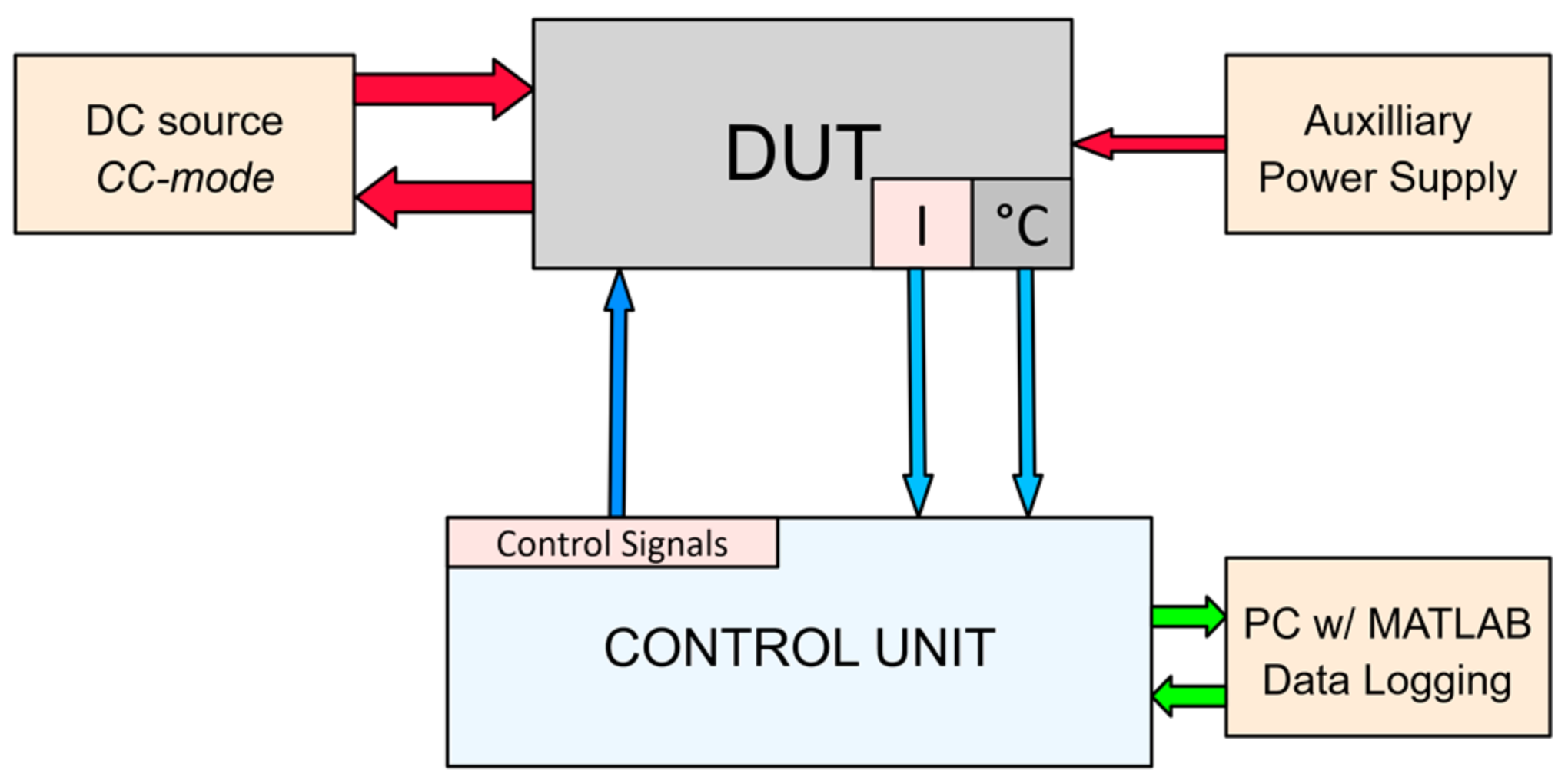
| Component | Description | Mark (Figure 6) |
|---|---|---|
| DC sources (×2) ET Systems LAB/HP101000 *1 | Umax = 1000 V; Imax = 20 A | 1 |
| Auxiliary power supply | U = 12 V; I = 3 A | 2 |
| IGBT test board | Assembled IGBT test board for temperature control development | 3 |
| Control unit (Arduino DUE) | 8 analog inputs + 4 digital outputs | 4 |
| PC with MATLAB | PC with MATLAB R2018b for Data acquisition and Start/Stop test function | 5 |
| Multimeter | Multimeter for load current measurement | 6 |
| Parameter | Description |
|---|---|
| T2 (bit) | Upper threshold temperature at which the IGBT will be turned OFF. This value is defined in the algorithm code. |
| T2 (°C) | Upper threshold temperature (in °C). |
| T1 (°C) | Lower threshold temperature (in °C). |
| Tmax (°C) | Maximum reached temperature in the test. |
| ΔT (bit) | Cooling hysteresis, which defines the lower threshold temperature at which the IGBT will be turned ON. This value is defined in the algorithm code. |
| theating (s) | Heating time or the IGBT conduction time (ON time). |
| tcooling (s) | IGBT cooling/resting time (OFF time). |
| Tovershoot (%) | Temperature overshoot in percent. |
| tovershoot (s) | Overshoot duration. |
| Nsim | NNr | ||||||||
|---|---|---|---|---|---|---|---|---|---|
| n | N | T2 (°C/Bit) | ΔT (Bit) | Time (s) | n | N + Nr | T2 (°C/Bit) | ΔT (Bit) | Time (s) |
| 1 | 3 | 74 °C/500 | 50 | 120 | 1 | 2 + 1 | 74 °C/500 | 50 | 120 |
| 2 | 3 | 90 °C/700 | 50 | 120 | 2 | 2 + 1 | 90 °C/700 | 50 | 120 |
| 3 | 3 | 90 °C/700 | 80 | 120 | 3 | 2 + 1 | 90 °C/700 | 80 | 120 |
| 3 IGBTs | IGBT 1 (Blue) | IGBT 2 (Red) | IGBT 3 (Yellow) | |||||||||
|---|---|---|---|---|---|---|---|---|---|---|---|---|
| T2 °C (bit) | 74 °C (500) | 90 °C (700) | 74 °C (500) | 90 °C (700) | 74 °C (500) | 90 °C (700) | ||||||
| ΔT (bit) | 50 | 80 | 50 | 80 | 50 | 80 | 50 | 80 | 50 | 80 | 50 | 80 |
| T1 (°C) | 72.8 | 69.5 | 88.9 | 86.3 | 72.7 | 70.5 | 89.4 | 86.5 | 72.4 | 69.6 | 89.0 | 86.5 |
| T2 (°C) | 73.8 | 73.4 | 90.4 | 90.3 | 72.0 | 70.1 | 89.5 | 90.5 | 74.2 | 74.7 | 90.0 | 90.6 |
| Tmax (°C) | 76.6 | 76.6 | 93.1 | 92.7 | 97.8 | 99.2 | 116 | 118 | 89.1 | 88.3 | 105 | 105 |
| theating (s) | 1.10 | 2.00 | 1.00 | 2.00 | 0.700 | 2.10 | 1.00 | 2.40 | 2.80 | 2.90 | 1.90 | 3.70 |
| tcooling (s) | 16.2 | 20.8 | 12.8 | 14.8 | 25.4 | 76.7 | 49.4 | 63.9 | 65.9 | 77.7 | 53.2 | 62.7 |
| Tovershoot (%) | 4.00 | 4.00 | 3.00 | 3.00 | 36.0 | 41.0 | 29.0 | 30.0 | 20.0 | 18.0 | 17.0 | 15.0 |
| tovershoot (s) | 3.20 | 2.60 | 2.70 | 3.00 | 6.20 | 6.60 | 8.50 | 7.00 | 11.9 | 12.4 | 11.1 | 12.1 |
| 2 + 1 IGBTs | IGBT 1 (Blue) | IGBT 2 (Red) | IGBT 3 (Yellow) | |||||||||
|---|---|---|---|---|---|---|---|---|---|---|---|---|
| T2 °C (bit) | 74 °C (500) | 90 °C (700) | 74 °C (500) | 90 °C (700) | 74 °C (500) | 90 °C (700) | ||||||
| ΔT (bit) | 50 | 80 | 50 | 80 | 50 | 80 | 50 | 80 | 50 | 80 | 50 | 80 |
| T1 (°C) | 73.1 | 70.2 | 89.3 | 87.1 | 72.6 | 69.5 | 89.0 | 87.2 | 70.2 | - | 84.6 | 82.2 |
| T2 (°C) | 74.0 | 73.9 | 90.1 | 90.6 | 74.4 | 73.9 | 91.0 | 90.9 | 74.2 | 73.1 | 90.7 | 82.8 |
| Tmax (°C) | 76.0 | 77.4 | 93.3 | 93.1 | 76.6 | 77.5 | 93.7 | 93.7 | 85.0 | 89.8 | 105 | 98.9 |
| theating (s) | 1.90 | 1.90 | 1.80 | 4.00 | 2.50 | 2.20 | 3.10 | 3.50 | 3.70 | - | 7.40 | 8.80 |
| tcooling (s) | 10.6 | 24.5 | 9.80 | 13.6 | 14.7 | 34.2 | 13.1 | 18.5 | 67.3 | - | 65.6 | 63.4 |
| Tovershoot (%) | 3.00 | 5.00 | 4.00 | 3.00 | 3.00 | 5.00 | 3.00 | 3.00 | 15.0 | 23.0 | 16.0 | 19.0 |
| tovershoot (s) | 3.80 | 2.70 | 2.90 | 2.50 | 3.30 | 3.50 | 3.40 | 3.40 | 11.3 | 11.5 | 11.2 | 11.9 |
Publisher’s Note: MDPI stays neutral with regard to jurisdictional claims in published maps and institutional affiliations. |
© 2021 by the authors. Licensee MDPI, Basel, Switzerland. This article is an open access article distributed under the terms and conditions of the Creative Commons Attribution (CC BY) license (http://creativecommons.org/licenses/by/4.0/).
Share and Cite
Brandis, A.; Pelin, D.; Matić, T.; Topić, D. Temperature Control Concept for Parallel IGBT Operation. Electronics 2021, 10, 429. https://doi.org/10.3390/electronics10040429
Brandis A, Pelin D, Matić T, Topić D. Temperature Control Concept for Parallel IGBT Operation. Electronics. 2021; 10(4):429. https://doi.org/10.3390/electronics10040429
Chicago/Turabian StyleBrandis, Andrej, Denis Pelin, Tomislav Matić, and Danijel Topić. 2021. "Temperature Control Concept for Parallel IGBT Operation" Electronics 10, no. 4: 429. https://doi.org/10.3390/electronics10040429