Article

Temperature Control Concept for Parallel IGBT Operation

Faculty of Electrical Engineering, Computer Science and Information Technology Osijek, Josip Juraj Strossmayer University of Osijek, 31000 Osijek, Croatia
*
Author to whom correspondence should be addressed.
Electronics 2021, 10(4), 429; https://doi.org/10.3390/electronics10040429
Submission received: 1 December 2020 / Revised: 2 February 2021 / Accepted: 4 February 2021 / Published: 9 February 2021
(This article belongs to the Section Power Electronics)

Abstract

:
This paper addresses the concept of load balancing in the operation of parallel insulated-gate bipolar transistors (IGBTs), in which the temperature is used as the main control parameter. In parallel IGBT operation, it is essential to ensure an equal load distribution across all IGBTs. Two basic algorithm concepts for temperature control were developed for the purpose of balancing. A test model based on the parallel IGBTs operation was assembled in a laboratory and the developed algorithms were tested for the chosen parameters. MATLAB was used for final data processing. The comparison between the two implemented basic algorithms provides insights into the temperature behavior of parallel IGBTs in terms of individual IGBT’s heating and cooling trajectories and time constants. All tests were conducted without the heatsinks to obtain the worst-case scenario in terms of thermal conditions. The test results show that temperature control in the operation of parallel IGBTs is possible but limited.

1. Introduction

Power electronic converters are used in many segments of modern industry, such as automotive, biomedical, and renewable energy systems, with a steady growth trend likely in future [1,2]. Every controllable power electronic converter has a certain type of a semiconductor implemented (mostly transistors), which in low- to high-power applications (power supplies, inverters, variable speed drive systems, etc.), is usually an insulated-gate bipolar transistor (IGBT). For high-power applications [3,4,5], a single transistor unit generally does not meet requirements related to current-voltage characteristics, therefore, parallel and/or series device operation is necessary. If voltage requirements are satisfied, to increase the required power, paralleling of devices is utilized. Two approaches can be used for this purpose: paralleling power electronics converters (e.g., inverters), for example, as presented by Wang et al. [6]; or using one converter with paralleled IGBT operation [7]. The main problem in IGBT parallel operation is the load imbalance due to uneven current distribution in individual IGBTs. This issue has received significant attention in the research literature [5,8,9,10,11,12,13,14].
Alvarez, Fink and Bernet in [8] present a simulative study on the influence of different parameters on the current distribution of parallel connected IGBTs. Dynamic problems in IGBT parallel operation are presented by Schlapbach in [9] and Jadhav, Zhou and Jansen in [10]. Current sharing problems between paralleled IGBT modules during short circuit are presented in [11] by Spang and Katzenberger. The influences of differences in switching behaviors are well presented in [12] by Schrader et al. The same problems regarding current distribution in parallel transistor operation also occur with different types of transistor, such as GaN or SiC [14]. In ref. [15], Yang et al. present the effect of unbalanced load in paralleled IGBTs, in addition to the results of IGBT temperature differences between individual transistors. Li et al. [16] present the problem of current imbalance in paralleled half-bridge power modules. Paralleling, which dies in power modules, also faces challenges regarding current distribution balance, as presented in [5].
The remedy for the issue of uneven current distribution between paralleled transistors is load balancing for IGBTs. According to [17], there are three main categories of parallel IGBT load balancing: the de-rating method, impedance balancing, and active gate control. The above methods have their specific advantages and disadvantages. A de-rating method is the simplest method and is based on the IGBT’s current rating reduction (i.e., device oversizing), in which the device current rating is set well above the power (current) demands [18]. This eliminates the consequences of IGBT’s current imbalances. The disadvantages of this method are undesirable €/W ratio, increased device dimensions, etc. The impedance balancing method includes a snubber (i.e., a resistor with several times greater resistance than differential resistance of each IGBT or a snubber transformer) in series with each parallel-connected IGBT. This method ensures almost equal current sharing [19]. A problem with this technique is higher power loss. If balancing transformers are used, the cost increases with the volume and weight of the device.
The last approach is the active gate control (open-loop and closed-loop) which includes an automatic control method for individual IGBTs [20,21,22,23,24,25]. Automated delay time compensation as an active gate control method is presented in [20] by Alvarez. Chen et al. in [21] use an active gate control method with two control loops for IGBTs’ parallel operation current balancing. Du et al. in [22] use parallel and series connected IGBTs balanced with an active gate control method via FPGA, which is the most common type of microcontroller unit (MCU) used in active gate control balancing methods. Zeng et al. [23] propose an artificial neural network control algorithm in the form of embedded hardware to deal with a current distribution imbalance. Active current balancing, as a form of independent delay control aiming to minimize current peaks during switching transients, is presented in [24] by Tripathi, Tsukuda and Omura. Beushausen, Herzog and Doncker [25] propose an active gate control in terms of voltage slope duCE/dt closed-loop control in medium-voltage applications.
The advantages of active gate control methods are precise load balancing, ability to balance a large number of paralleled IGBTs (depending on the selected embedded system), and volume and weight does not increase significantly with a higher number of IGBTs. The disadvantages are complicated control and decreased reliability compared to the de-rating and impedance balancing methods. All research papers related to IGBT paralleling are based on the idea of current balancing.
Another option for IGBT load balancing is via the IGBT temperature because the temperature and current are directly correlated. This idea is even more interesting because the transistor reliability and lifespan directly depend on IGBT’s operation temperature [26]. Moreover, IGBTs have among the highest failure rates of components in power electronic converters due to temperature fluctuation, as proposed by Wang in [27]. Thus, the stable operation temperature of every transistor is important for the reliability of converters with parallel IGBTs implemented.
To our knowledge, paralleled IGBTs’ load balancing via temperature control (as a primary or secondary control along the current) has not been explored yet. This paper provides insights and presents important conclusions regarding the paralleled IGBT temperature control concept. Temperature can be used as the only feedback parameter to control IGBTs with simple algorithms, as presented in this research. Two original control algorithms, Nsim and NNr, were developed, implemented on an embedded system board, and tested on a laboratory IGBT test board. Detailed flowcharts for both algorithms are presented and elaborated in the paper. IGBTs’ temperature responses to the emitter current were obtained in the form of diagrams to present the temperature time constants, i.e., heating and cooling times for specific parameters. In addition, we developed our own data logging and data processing system, as presented in the paper and available as Supplementary Materials in back matter in the form of Arduino codes (NNr_Nsim_Arduino_code.zip) and MATLAB scripts (MATLAB_code_v1.5.zip).
The remainder of this paper is organized as follows. Section 2 gives an overview of the assembled IGBT test boards. The developed algorithms for load balancing via IGBT temperature control are outlined in Section 3. The experimental analysis is given in Section 4. Finally, the final section concludes and provides remarks regarding future work.

2. Assembled IGBT Test Board

An initial design idea for the test board was to develop a test model on which different temperature control algorithms could be tested. Thus, four IGBTs were installed on the developed test board as a minimal set requirement for two developed algorithms, which are presented later in the paper. The block schematic of the test model is shown in Figure 1. Here, four IGBTs (IGBT1–IGBT4) are utilized. IGBT drivers (GD1–GD4) are connected to every IGBT on one side and to the control unit on the other side. Each IGBT has its own NTC temperature sensor Cantherm MF58 (Quebec, Montreal, Canada) and current sensor (transducer) LEM LTS 25-NP (Wisconsin, MKE, USA). The development board with a 32-bit ARM AT91SAM3X8E Arduino DUE (Torino, Italy) microcontroller was used as a control unit [28]. The used development board is restricted to sixteen analog inputs (current and temperature readings), which is acceptable for the assembled test model (four current and four temperature readings). IGBT drivers are controlled with digital outputs. An auxiliary power supply of 12 V and 3 A was used as a power supply for the test model.
The list of electronic components of the test model with the markings according to Figure 2, is given in Table 1. The assembled test board is shown in Figure 2. The used IGBTs were Fairchild SGH80N60UFD (South Portland, ME, USA) (600 V; 40 A) IGBTs in the TO-3P package (mark 1; Figure 2) [29]. These transistors do not have integrated temperature sensors thus, dedicated temperature sensors were installed. The chosen temperature sensors were 100k NTC thermistors (mark 2; Figure 2). In the bottom-left corner of Figure 2 (magnified), a solution to NTC installation with the IGBTs is illustrated. The NTCs are attached with thermal glue to the back of the IGBTs (directly connected to the emitter leg). Special attention was paid to the placement and gluing of the NTCs so that they could have as identical thermal properties as possible. Other important parts of the test board were current transducers (In = 8 A)—mark 3; Figure 2, and IGBT drivers Microchip TC4420 (Chandler, Arizona, USA) (CMOS/TTL, Ip = 6 A)—mark 4; Figure 2.
The test board was supplied with +12 V and +5 V stabilized power source for drivers and sensors (mark 5; Figure 2). The +5 V stable voltage source is crucial for precise current and temperature measurements. Further, every current and temperature sensor has its own active circuitry for calibration and fine adjustments realized via multiple-turn trimmers (mark 6; Figure 2) and other passive components to ensure reliable measurements.
Furthermore, additional useful features were the installed green Light-Emitting Diodes (LEDs; mark 7; Figure 2), which were activated when IGBTs conduct electricity so the user can see when IGBTs conduct. The load was connected via 4 mm banana plugs (mark 8; Figure 2). The control and power sections of the test board had a common ground (pin headers marked with 9; Figure 2). The four digital outputs of the control unit for IGBTs control were connected to the input of gate drivers (pin headers marked with 10; Figure 2). A total of eight pin headers (mark 11; Figure 2) were dedicated for IGBT current and temperature measurements via the control unit (four current and four temperature). Control unit analog input pins were set to 10-bit resolution and 250 Hz sampling frequency per analog input.

3. Developed Algorithms

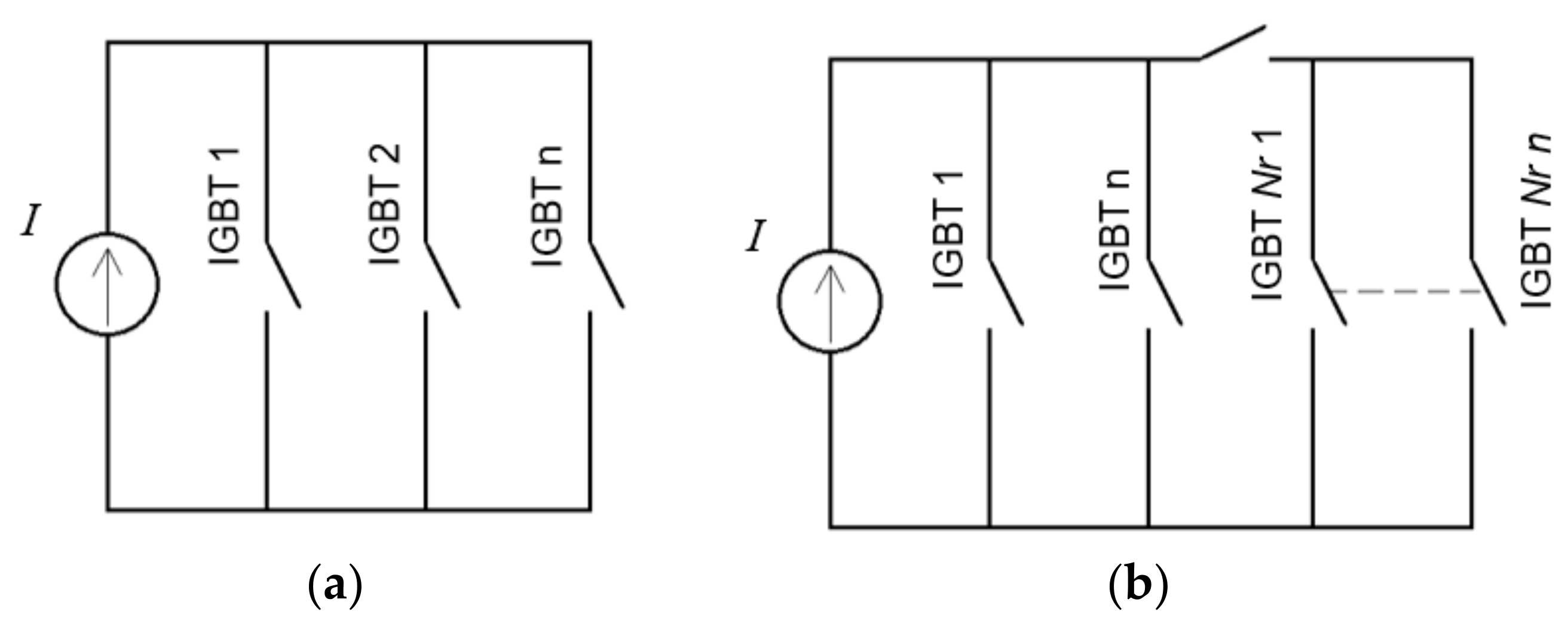
In this study, two algorithms were developed for basic IGBT load balancing via temperature control—Nsim and NNr. The basic schematic of both Nsim and NNr algorithms is shown in Figure 3. These two algorithms are chosen to show two different but similar simple methods of paralleled IGBT temperature control (one without and one with redundant IGBTs) and to validate both methods.
The developed algorithms have features regarding safety, such as maximum temperature and current protection as well as a required system reset when software parameters change implemented. In the following subsections two algorithms are elaborated on.

3.1. Nsim Algorithm

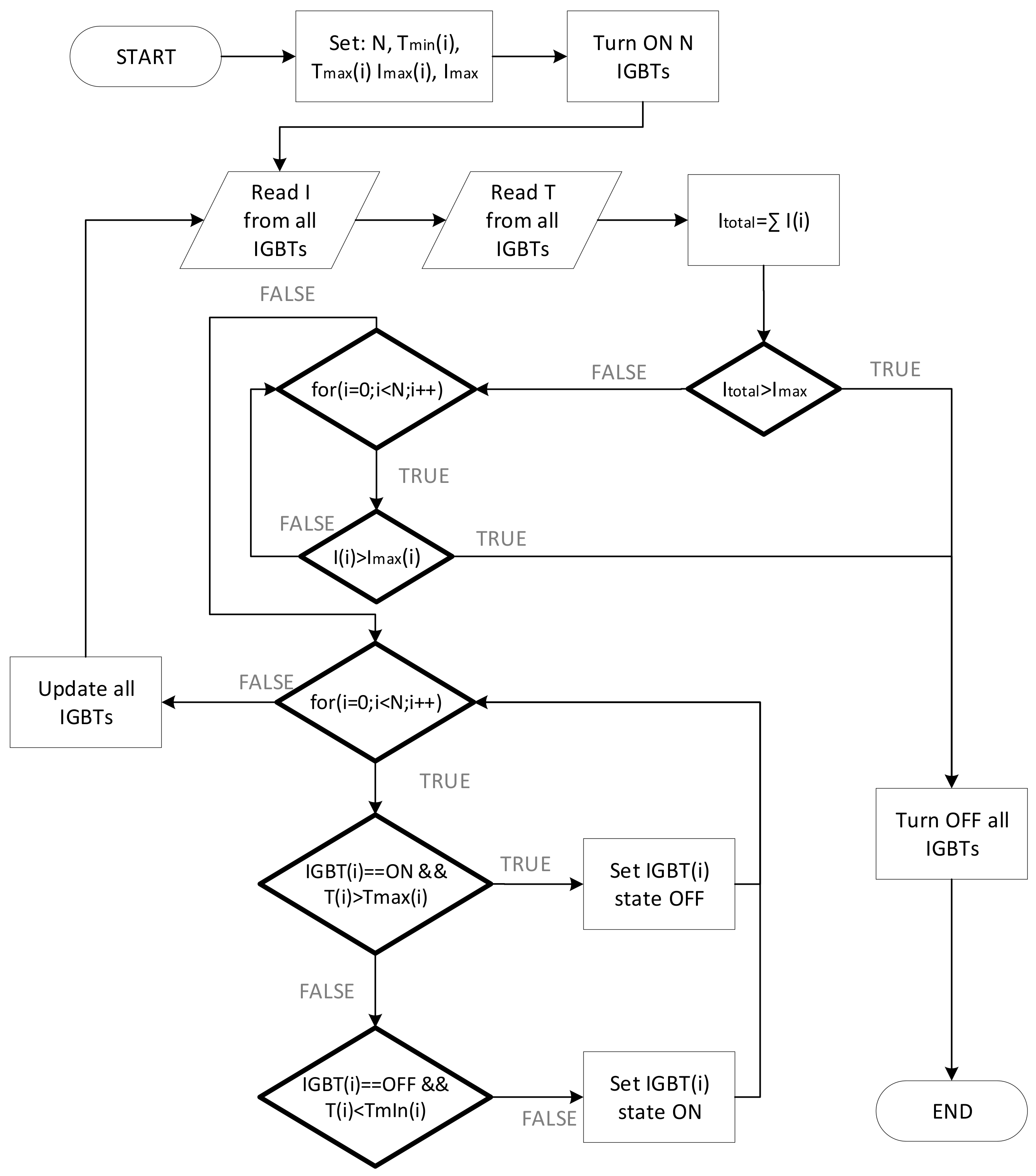
The Nsim algorithm represents the algorithm for IGBT control in which all IGBTs work simultaneously. The working principle of the Nsim algorithm is that all IGBTs work simultaneously until the maximum temperature of any individual IGBT (T2(i)) is reached (Figure 3). An IGBT with temperature T2(i) or greater is disabled and it cools down. When the temperature of a given IGBT is T1(i) or lower, the IGBT is engaged again. This principle is applied to every engaged IGBT.
The algorithm is initialized with the following parameters:
  • N—number of engaged IGBTs;
  • T2(i), i = 1, 2, …, N—upper temperature threshold or the maximum temperature of the IGBT when the IGBT is disabled;
  • T1(i), i = 1, 2, …, N—lower temperature threshold or the temperature at which the IGBT is engaged again after cooling down from T2(i);
  • Imax—sum of all IGBT currents or the value of the current at which the system shuts down all IGBTs and the test ends;
  • Imax(i), i = 1, 2, …, N—maximum current of an individual IGBT or the value of the current at which all IGBTs are disabled and the test ends.
The flowchart of the Nsim algorithm is given in Figure 4.

3.2. NNr Algorithm

The NNr algorithm represents the algorithm for IGBT control in which the N IGBTs are initially engaged as the main IGBTs and Nr as redundant IGBTs, which are engaged if any of the main IGBTs reaches the upper threshold temperature T2. Initial parameters T2(i), T1(i), Imax, Imax(i) are the same as those of the Nsim algorithm, with the difference of the two additional parameters:
  • N—number of the main engaged IGBTs;
  • Nr—number of redundant IGBTs.
The basic working principle of NNr is that the user first selects the N number of main IGBTs and Nr number of redundant IGBTs (Figure 3). Redundant IGBTs are simultaneously engaged when any of the main IGBTs reaches T2(i). They remain active until all individual IGBTs from the main group of IGBTs cool down (reaches T1(i)). At this point, redundant IGBTs are deactivated and only the N main IGBTs conduct again. This algorithm ensures better stability of the system but also requires a greater number of IGBTs due to redundancy. The flowchart of the NNr algorithm is given in Figure 5.

4. Experimental Results

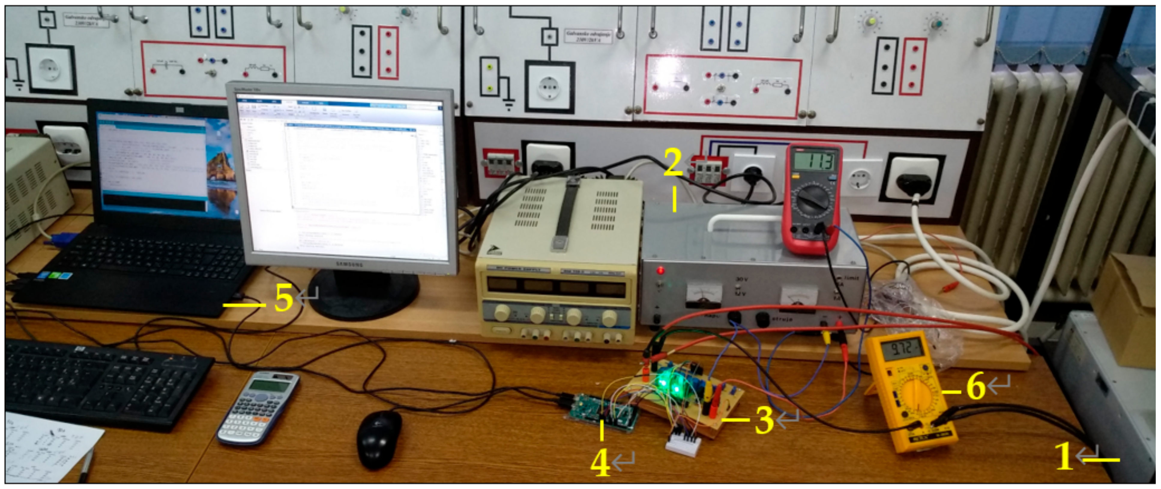
Both Nsim and NNr algorithms were developed and tested on the test board. The test bench is shown in Figure 6.
Table 2 lists the equipment used in the test setup.
Generally, two working modes—switching and conduction—are significant for IGBT operation testing. A switching operation mode is significant to test when dynamic current is controlled and observed due to unavoidable differences in transients during on/off switching periods. This operation mode allows IGBTs to have room for cooling (during off periods), which is beneficial for faster cooling (slower heating) transients. The conduction mode means that IGBT is continuously in the on state during the test. This paper focuses on the latter operation mode because it is the worst-case scenario in terms of IGBT loading and heating. Thus, all measurements in the paper were made for a conduction mode. It is important to mention that all four IGBTs were not from the same batch, and some were changed a few times due to failure. This creates an even more unbalanced situation between IGBTs, which is suitable for this research due to an even more pronounced imbalance of current and temperature characteristics.
Because the main objective is to heat the transistors, to avoid the need for a specific load and load losses (e.g., in the case of using a DC source in a constant-voltage (CV) mode and working load), a DC source in a constant-current (CC) mode was used instead. This simplified the test setup and reduced test setup components. The current source was set to a constant of 20 A due to DC source limitations.
In addition, it is worth mentioning that all measurements were done without a heatsink to obtain the fastest IGBT heating and slowest cooling (worst-case scenario). The measurements are aimed to provide an insight into IGBT temperature behavior and algorithm analysis for future upgrades. The measurements on the test model are organized in such a way to analyze the influence of all characteristic parameters.
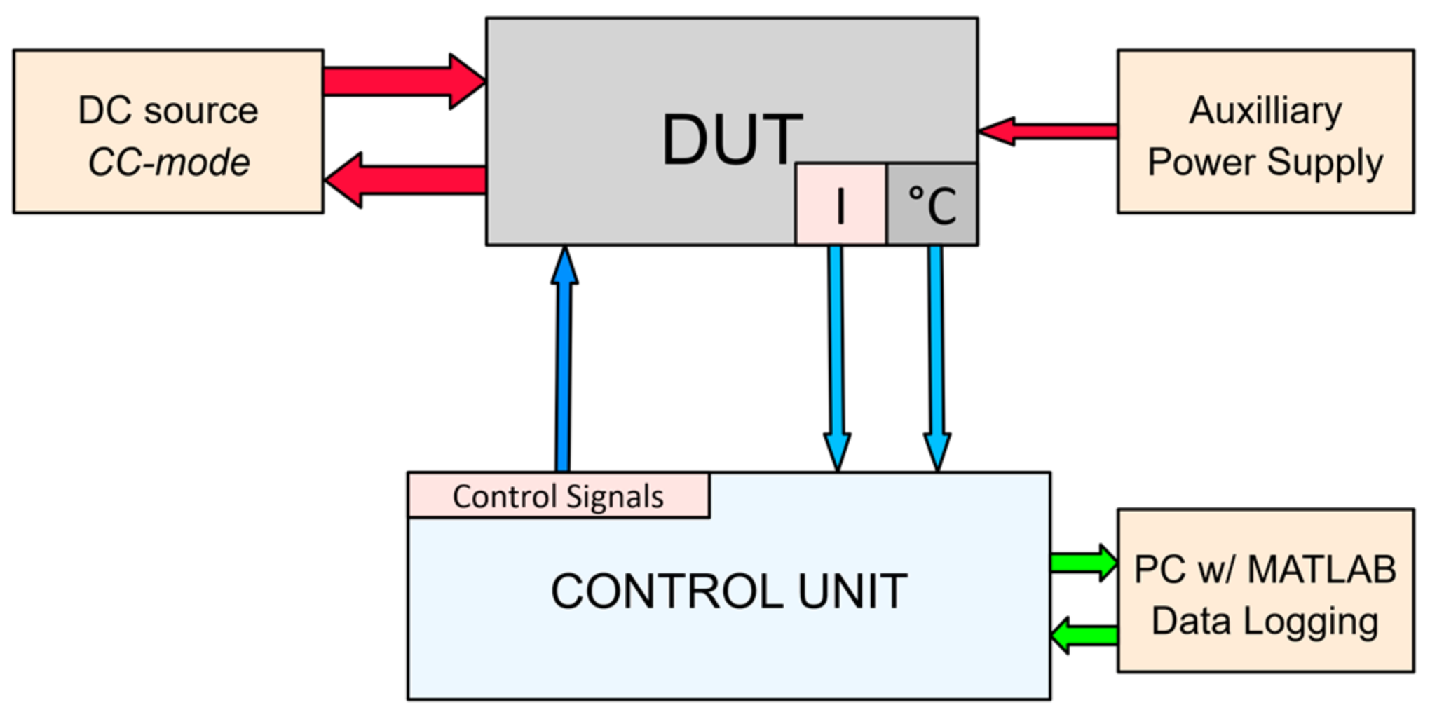
A block schematic of the test circuit is shown in Figure 7.
The block schematic (Figure 7) shows the basic blocks of the test setup. Here, the device under test (DUT) consisted of four paralleled IGBTs with attached drivers, and current and temperature sensors. An auxiliary power supply fed sensors and drivers. An Arduino DUE sent control signals to the gate drivers of the IGBTs according to the temperature and current feedback from the sensors.
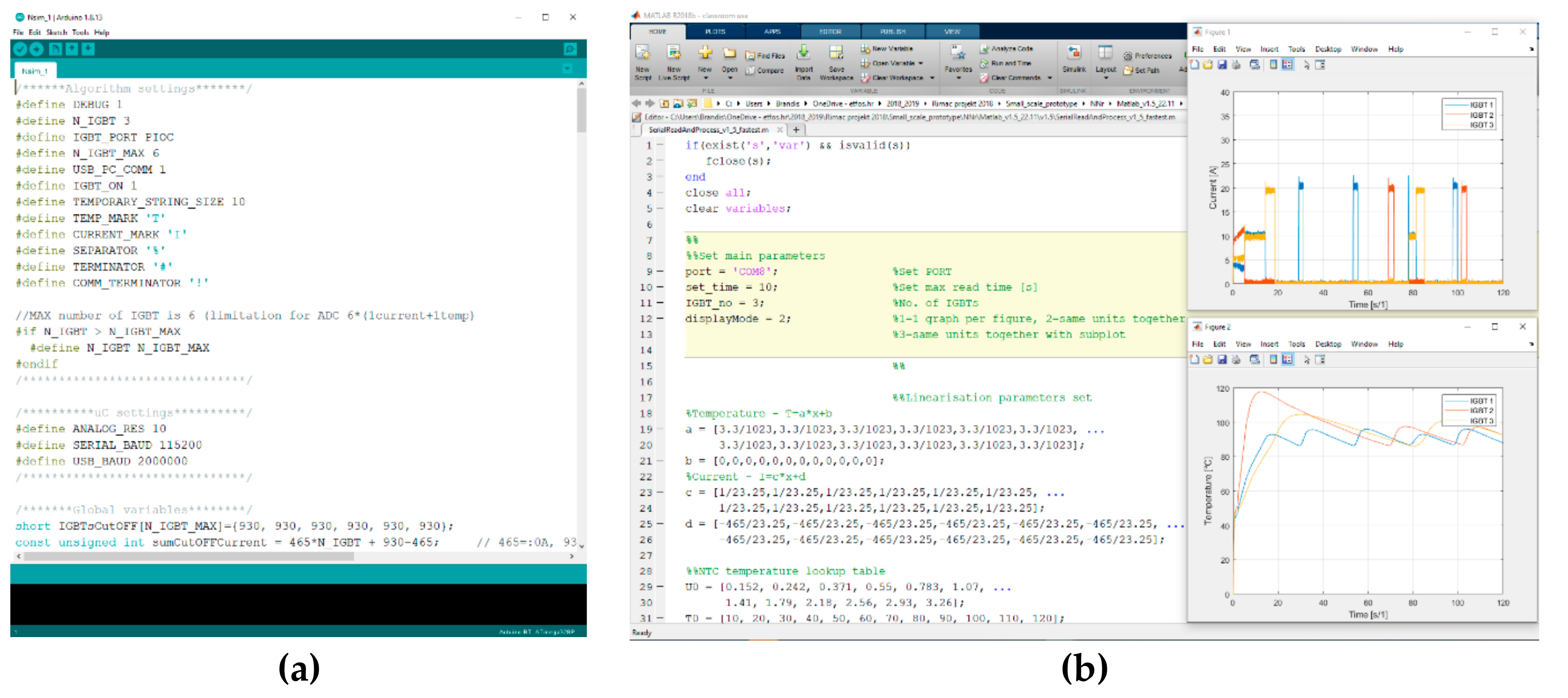
A development board (Arduino DUE) has two USB ports—a programming port and native port. With the programming port, all available algorithm parameters can be set and uploaded to the MCU via the human-machine interface (HMI) (Figure 8a). Once uploaded, the algorithm waits for a command from the native USB port to run itself. The native USB port is used as a virtual serial port for data readings and algorithm control with MATLAB. An additional MATLAB script was written to enable fast data readings (480 Mbit/s) and data conversion of the measured values.
The MATLAB HMI is shown in Figure 8b. In this interface, the test duration and the processed data display options can be set. The MATLAB script also enables the algorithm to start when the Run button is pressed. With the same button, the algorithm can be forcibly interrupted. Upon finishing the test, MATLAB processes the recorded data and draws the selected graphs as can be seen in Figure 8b.
The processed data example, together with the description of the selected parameters (Table 3), is given in Figure 9.
Over 50 measurements with different parameters were made, and the measurement results for three significant different operating points for both Nsim and NNr algorithms are presented in the paper (Table 4).
Because the accuracy of the temperature and current readings is important, sensors integration is briefly discussed. In addition to the datasheet parameters [30] and MATLAB resistance calculation, simulation of the NTC circuit was conducted using a SPICE (Simulation Program with Integrated Circuit Emphasis) program National Instruments (NI) Multisim [31] to obtain the NTC circuit voltage readings. The test board was calibrated before the initial measurements via trimmers (mark 6; Figure 2) and all values were rechecked (and recalibrated if needed) before each set of measurements. The NTC circuit calibration was done in the idle state for every individual IGBT at the room temperature of 25 °C. Due to the lack of a temperature test chamber, only a single temperature check point (25 °C) was verified. The accuracy of the temperature measurements relies on temperature characteristics obtained by simulation. The characteristic calculation was undertaken using the Steinhart-Hart curve fitting method [32]. Taking into account the estimated uncertainty of the Steinhart-Hart method [32], R25 and B value tolerances of 1% and 2%, respectively [30], and the NTC installation method, our rough estimation is that the temperature readings should be within the range of ±5 °C at 80–100 °C operation temperature.
The current sensor has an accuracy of ±1%, which was confirmed with an additional current meter METEX M-3650 (Seoul, Geumcheon-gu, South Korea) connected in series with the load (Figure 6).

4.1. IGBT Current-Temperature Characteristic

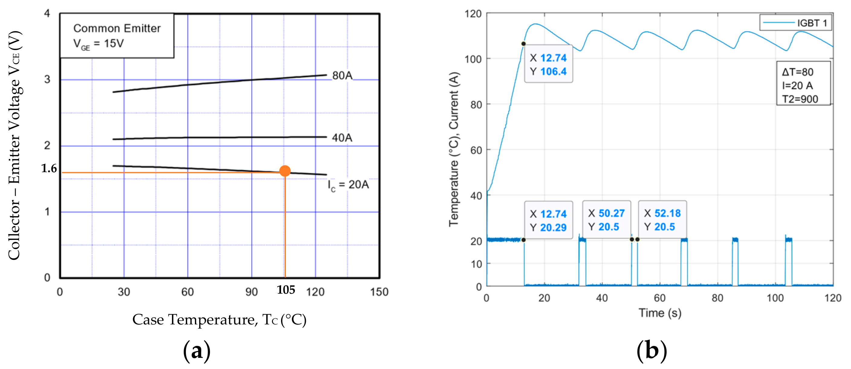
Because this paper addresses temperature and current as the two main observed variables, the current-temperature characteristic is discussed prior to measurements. The only current-temperature correlation characteristic available from the Fairchild SGH80N60UFD datasheet [29] is extracted and shown in Figure 10a. In Figure 10b, the recorded current and temperature characteristic of a single IGBT for the chosen parameters of T2 = 105 °C, I = 20 A, and ΔT = 80 is shown.
In the case presented in Figure 10a, for the emitter (or collector) current of I = 20 A, at the chosen operation temperature of the IGBT of T2 = 105 °C and the collector-emitter voltage VCE = 1.6 V, the steady state power losses can be estimated as:
P l o s s = V CE · I = 1.6 · 20 = 32   W
Because the current source is used in the form of the load in this paper, the steady state IGBT power losses can be easily confirmed by reading the power of the source which, in this case, amounts to P = 38   W . The deviation between the calculated and measured values can be attributed to the model design flaws and to the gate-emitter VGE voltage. In our model, the gate-emitter voltage amounts to 12 V; however, datasheet characteristics (Figure 10a) are only available for 15 V gate-emitter voltage used for the aforementioned losses. The lower the VGE, the higher the power losses [29].
The constant current increases IGBT case temperature almost linearly (in this case, approximately 6.5 °C/s) as illustrated in Figure 10b. The temperature compensation in this case is simply achievable. When IGBT comes to the set temperature T2 = 105 °C, it stays at this working point continuously until the end of the test. Because only a single IGBT is used in this case, there is no other transistor to compensate for the load. To overcome this, paralleled transistors can be used.

4.2. Measurements on Nsim Algorithm

In this subsection, processed measurement data of the implemented Nsim algorithm are presented. The measurements are done for the selected parameters pursuant to Table 4. The parameters for the control unit are defined in bits. The temperature values in bits are converted to °C according to the datasheet of MF58 and the designed circuit for temperature measurement [30]. This conversion was executed in MATLAB. It is worth mentioning that the parameter ΔT is given only in bit values due to a non-linear NTC characteristic.
The developed test board has four IGBTs installed but only three were engaged in the experiments due to DC current source limitations. The measurement results for three paralleled IGBTs are provided in Figure 11 and Figure 12. The processed data summary for these measurements (Figure 11 and Figure 12) is illustrated in Table 5.
The current distribution in the case of three paralleled IGBTs is uneven, as shown in Figure 11. In this case, the red IGBT takes most of the current and heats up fastest (below 1 s). Physical placement of the red IGBT is between yellow and blue, thus it is additionally heated through the bus by the adjacent IGBTs. It should be noted that the imperfection in the physical design of the test model (bus placement and design, differences in impedance paths) and IGBT temperature overloading during the previous tests can lead to greater unevenness of IGBT current distribution. The red IGBT has the largest overshoot (>30%; Table 5), which can damage the transistor. The overshoot phenomenon, in fact, damaged a few IGBTs during the tests, so transistors had to be replaced with new ones. Consequently, T2 must be carefully chosen. The proposed test model does not have any cooling option, thus, even the current of 10 A for this type of a transistor will be relatively high. In real applications, where the heatsink is used, the overshoot is expected to be diminished. The higher the value of T2, the longer the device operates.
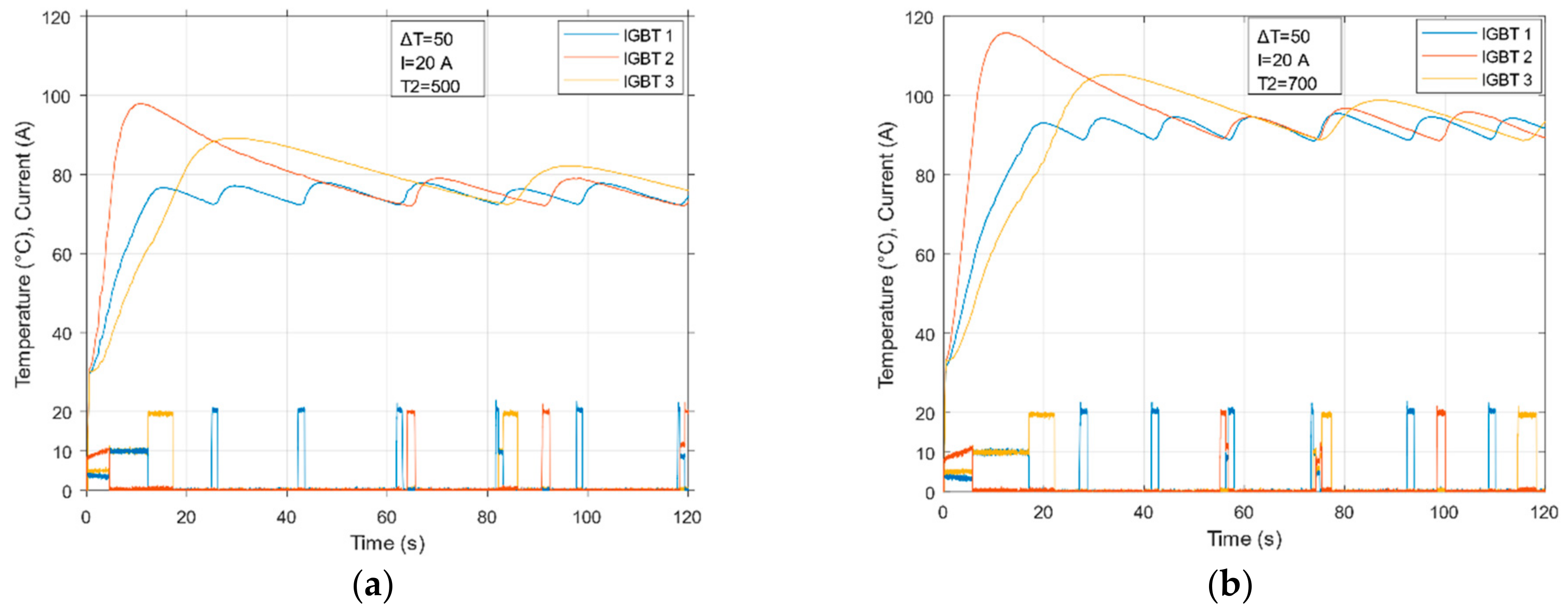
The influence of different values of ΔT is shown in Figure 12. In the case of higher ΔT, the IGBT cooling time is longer.
A few observations must be mentioned regarding the Nsim algorithm measurements. The data in Figure 11 and Figure 12, and those in Table 5, indicate that the operation of the system will be interrupted at some point. Regardless of the settings implemented in the algorithm, due to the lack of a heatsink, even a small amount of current (e.g., less than 1 A) will raise the temperature to the desired limit within a given specific time. The most important parameters are heating and cooling times (time constants) of IGBTs, which, in the best-case scenario, amount to 3.7 s for heating and 12.8 s for cooling (Table 5). For the worst-case scenario, the opposite is true, i.e., when heating is the fastest (0.7 s) and cooling is the slowest (77.7 s). Finally, the device operation time can be prolonged (if no heatsink is used and with the same load added) either by increasing the threshold temperature T2 or by increasing the number of parallel IGBTs.

4.3. Measurements on NNr Algorithm

The NNr algorithm was developed as an alternative to Nsim and to be able to prolong the operation time before the first interruption of the test device (slower heating). Physically, everything was the same as with the Nsim algorithm. The measurements were done for the selected parameters pursuant to Table 4. The measurement results for two main and one redundant IGBT are presented in Figure 13 and Figure 14.
The influence on IGBT temperature characteristics when parameter T2 is changed is demonstrated in Figure 13. As with the Nsim algorithm, with a higher value of the upper threshold temperature, the device operation is prolonged. The current distribution is nearly identical for both T2 measurements (about 10 A per IGBT). The redundant IGBT activates later if a higher T2 is used, which is expected. The operation time of the NNr 2 + 1 algorithm (two main and one redundant IGBT; three IGBTs in total) is over 40 s, as presented in Table 6. The influence of different values of ΔT in the 2 + 1 NNr algorithm is shown in Figure 14.
The hysteresis ΔT influence is presented in Figure 14. Parameter ΔT dictates the duration of the redundant IGBT interaction. Thus, with the optimal choice of ΔT, the device operation can be prolonged including more efficient balancing. A detailed data analysis for 2 + 1 NNr algorithm measurements is given in Table 6.
A few crucial points regarding the NNr algorithm measurements need to be addressed. The current distribution is almost the same across all IGBTs, although some current discrepancies can be seen in Figure 13 and Figure 14. This influences uneven temperature rising for red and blue IGBTs (the higher the current, the faster the heating). When higher threshold temperature T2 is used, the device operation time is significantly prolonged. The measurement results (Table 6) lead to an assumption that an optimal number of redundant IGBTs exist. This can be determined by the physical dimension of the device, control unit capability, and price.

4.4. Nsim and NNr Algorithm Comparison

Because this paper addresses temperature control, three measured values, namely heating time, cooling time, and overshoot, directly depend on IGBT thermal conditions. Pursuant to Table 5 and Table 6, a chart is presented (Figure 15) for both Nsim and NNr algorithms for the chosen parameters of T2 = 90 °C and ΔT = 80 which compares the three most important measured values.
As can be seen from Figure 15, all IGBTs in both algorithms are heated to the threshold temperature T2 = 90 °C in less than 4 s, with the exception of IGBT 3 in the NNr algorithm because that is the redundant IGBT which has more time to rest than the other two (Figure 13 and Figure 14). The most pronounced overshoot of 30% is in the Nsim algorithm in IGBT 2, which is induced by the largest emitter current of about 10 A, whereas the remainder of the current of 10 A is shared between the other two transistors (Figure 11 and Figure 13). This also produced the longest cooling time (63.9 s) of the IGBT 2 transistor. When compared to the Nsim algorithm, within the same number of engaged IGBTs, the NNr algorithm operates significantly longer than the Nsim algorithm (over 40 s versus less than 25 s).

5. Conclusions

The main problem in the parallel operation of IGBTs is the uneven current distribution, which leads to temperature differences among individual transistors. This directly affects IGBT lifespans. In contrast to the common method for current balancing, an alternative approach that implies simple temperature control is proposed in this paper.
A physical test model was built for the verification of the results. In the case of the presented model, the higher IGBT operation temperature of 90 °C (measured on the back of the IGBT) is preferable because it prolongs operation time by more than 10% for every measurement and produces more suitable temperature time constants (slower heating and faster cooling). Without heatsinks, the IGBTs produced a significant temperature overshoot (in some cases over 40%). Due to this upper threshold, the temperature must be carefully chosen.
The unbalanced operation of paralleled IGBTs is significantly emphasized in Nsim measurements, in which a single IGBT conducted over 50% of the total current in a short time, which led to a current overshoot of 30% for that particular IGBT.
The NNr algorithm provided longer device operation (over 40 s versus 20 s for Nsim) and resulted in more balanced current distribution than the Nsim algorithm for the total of three utilized IGBTs in both cases.
The concept of temperature balancing with more advanced control algorithms remains open for future work.

Supplementary Materials

The following are available online at https://doi.org/10.6084/m9.figshare.c.5296645.v1, MATLAB scripts: MATLAB_code_v1.5.zip, Arduino algorithm codes: NNr_Nsim_Arduino_code.zip.

Author Contributions

Conceptualization, D.P., T.M. and A.B.; methodology, A.B., D.P. and T.M.; validation, D.P. and T.M.; formal analysis, A.B., D.P. and T.M.; investigation, A.B.; writing—original draft preparation, A.B.; writing—review and editing, D.P., T.M., and D.T.; visualization, A.B., D.P. and T.M.; supervision, D.P., T.M. and D.T.; project administration, D.T. All authors have read and agreed to the published version of the manuscript.

Funding

This work was funded by the European Union through the European Regional Development Fund Operational Programme Competitiveness and Cohesion 2014–2020 of the Republic of Croatia under project KK.01.1.1.04.0034 “Connected Stationary Battery Energy Storage”.

Data Availability Statement

Data available in a publicly accessible repository. The data presented in this study are openly available in Figshare at https://doi.org/10.6084/m9.figshare.c.5296645.v1, reference number 10.6084/m9.figshare.c.5296645.v1.

Conflicts of Interest

The authors declare no conflict of interest.

References

  1. Rodrigues, E.M.G.; Godina, R.; Pouresmaeil, E. Industrial Applications of Power Electronics. Electronics 2020, 9, 1534. [Google Scholar] [CrossRef]
  2. Nguyen, M.-K. Power Converters in Power Electronics: Current Research Trends. Electronics 2020, 9, 654. [Google Scholar] [CrossRef]
  3. Hermansson, W.; Chimento, F.; Jonsson, T. Robustness Evaluation of High Voltage Press Pack IGBT Modules in Enhanced Short Circuit Test. In Proceedings of the IEEE Energy Conversion Congress and Exposition, Atlanta, GA, USA, 12–16 September 2010. [Google Scholar]
  4. Feng, L.; Gou, R.; Zhuo, F.; Yang, X.; Zhang, F. Development of a 10 kV Solid-State DC Circuit Breaker Based on Press-Pack IGBT for VSC-HVDC System. In Proceedings of the 2016 IEEE 8th International Power Electronics and Motion Control Conference (IPEMC-ECCE Asia), Hefei, China, 22–26 May 2016; pp. 2371–2377. [Google Scholar]
  5. Brandelero, J.; Ewanchuk, J.; Mollov, S. Selective Gate Driving in Intelligent Power Modules. IEEE Trans. Power Electron. 2020, 36, 13. [Google Scholar] [CrossRef]
  6. Wang, X.; Qing, H.; Huang, P.; Zhang, C. Modeling and Stability Analysis of Parallel Inverters in Island Microgrid. Electronics 2020, 9, 463. [Google Scholar] [CrossRef] [Green Version]
  7. Chen, N.; Chimento, F.; Nawaz, M.; Wang, L. Dynamic Characterization of Parallel-Connected High-Power IGBT Modules. In Proceedings of the 2013 IEEE Energy Conversion Congress and Exposition, Denver, CO, USA, 15–19 September 2013; pp. 4263–4269. [Google Scholar]
  8. Alvarez, R.; Fink, K.; Bernet, S. Simulation and Experimental Investigation of Parallel Connected IGBTs. In Proceedings of the 2010 IEEE International Conference on Industrial Technology, Vi a del Mar, Chile, 14–17 March 2010; pp. 824–831. [Google Scholar]
  9. Schlapbach, U. Dynamic Paralleling Problems in IGBT Module Construction and Application. In Proceedings of the 6th International Conference on Integrated Power Electronics Systems, Nuremberg, Germany, 16–18 March 2010; pp. 1–7. [Google Scholar]
  10. Jadhav, V.; Zhou, Y.; Jansen, U. Analysis of Different IGBT Gate Driver Strategies Influencing Dynamic Paralleling Performance. In Proceedings of the PCIM Asia 2016; International Exhibition and Conference for Power Electronics, Intelligent Motion, Renewable Energy and Energy Management, Shanghai, China, 28–30 June 2016; pp. 1–9. [Google Scholar]
  11. Spang, M.; Katzenberger, G. Current Sharing between Parallel IGBTs in Power Modules during Short Circuit with Unsymmetrically Connected Load. In Proceedings of the 2016 18th European Conference on Power Electronics and Applications (EPE’16 ECCE Europe), Germany, Karlsruhe, 5–9 September 2016; pp. 1–9. [Google Scholar]
  12. Robin, S. Influences of Gate-Circuit and Parasitic Inductances on Turn-Off Current Imbalances of Paralleled IGBTs Due to Differences in Their Switching Behaviour. In Proceedings of the 2018 20th European Conference on Power Electronics and Applications (EPE’18 ECCE Europe), Riga, Latvia, 17–21 September 2018; pp. 1–10. [Google Scholar]
  13. Su, H.; Wang, L.; Zhao, F.; Wang, L.; Luo, J. A Novel Electrical Evaluation Approach for Inhomogeneous Current Distribution in Parallel-Connected IGBT Modules. In Proceedings of the 2018 IEEE International Symposium on the Physical and Failure Analysis of Integrated Circuits (IPFA), Singapore, 16–19 July 2018; pp. 1–4. [Google Scholar]
  14. Zhu, N.; Chen, M.; Yan, R.; Mantooth, A.; Xu, D. Die Current Balancing of a Press-Pack SiC MOSFET. In Proceedings of the 2018 IEEE Energy Conversion Congress and Exposition (ECCE), Portland, OR, USA, 23–27 September 2018; pp. 5824–5830. [Google Scholar]
  15. Yang, J.; Che, Y.; Ran, L. Evaluation of Frequency and Temperature Dependence of Power Losses Difference in Parallel IGBTs. IEEE Access 2020, 8, 104074–104084. [Google Scholar] [CrossRef]
  16. Li, H.; Zhou, W.; Wang, X.; Munk-Nielsen, S.; Li, D.; Wang, Y. Influence of Paralleling Dies and Paralleling Half-Bridges on Transient Current Distribution in Multichip Power Modules. IEEE Trans. Power Electron. 2018, 33, 6483–6487. [Google Scholar] [CrossRef]
  17. Chen, Y.; Zhuo, F.; Pan, W.; Zhang, F.; Feng, L. A Novel Active Gate Driver for Static and Dynamic Current Balancing of Parallel-Connected IGBTs. In Proceedings of the 2017 IEEE Applied Power Electronics Conference and Exposition (APEC), Tampa, FL, USA, 26–30 March 2017; pp. 795–799. [Google Scholar]
  18. Sasaki, M.; Nishio, H.; Ng, W.T. Dynamic Gate Resistance Control for Current Balancing in Parallel Connected IGBTs. In Proceedings of the 2013 Twenty-Eighth Annual IEEE Applied Power Electronics Conference and Exposition (APEC), Long Beach, CA, USA, 17–21 March 2013; pp. 244–249. [Google Scholar]
  19. Shammas, N.Y.A.; Withanage, R.; Chamund, D. Review of Series and Parallel Connection of IGBTs. IEE Proc. Circuits Devices Syst. 2006, 153, 34. [Google Scholar] [CrossRef]
  20. Alvarez, R.; Bernet, S. A New Delay Time Compensation Principle for Parallel Connected IGBTs. In Proceedings of the 2011 IEEE Energy Conversion Congress and Exposition, Phoenix, AZ, USA, 17–21 September 2011; pp. 3000–3007. [Google Scholar]
  21. Chen, Y.; Zhuo, F.; Zhang, F.; Pan, W.; Yang, Y. A Novel Method for Current Balancing between Parallel-Connected IGBTs. In Proceedings of the 2016 18th European Conference on Power Electronics and Applications (EPE’16 ECCE Europe), Karlsruhe, Germany, 5–9 September 2016; pp. 1–8. [Google Scholar]
  22. Du, X.; Zhuo, F.; Sun, H.; Yi, H.; Zhu, Y. An Integrated Voltage and Current Balancing Strategy of Series-Parallel Connected IGBTs. In Proceedings of the 2018 International Power Electronics Conference (IPEC-Niigata 2018 -ECCE Asia), Niigata, Japan, 20–24 May 2018; pp. 2780–2784. [Google Scholar]
  23. Zeng, X.; Li, Z.; Wan, J.; Zhang, J.; Ren, M.; Gao, W.; Li, Z.; Zhang, B. Embedded Hardware Artificial Neural Network Control for Global and Real-Time Imbalance Current Suppression of Parallel Connected IGBTs. IEEE Trans. Ind. Electron. 2020, 67, 2186–2196. [Google Scholar] [CrossRef]
  24. Tripathi, R.N.; Tsukuda, M.; Omura, I. Peak Minimisation Based Gate Delay Compensation for Active Current Balancing of Parallel IGBT System. Microelectron. Reliab. 2019, 100–101. [Google Scholar] [CrossRef]
  25. Beushausen, S.; Herzog, F.; Doncker, R.W.D. GaN-Based Active Gate-Drive Unit With Closed-Loop Du/Dt-Control for IGBTs in Medium-Voltage Applications. In Proceedings of the PCIM Europe Digital Days 2020; International Exhibition and Conference for Power Electronics, Intelligent Motion, Renewable Energy and Energy Management, Germany, 7–8 July 2020; pp. 1–8. [Google Scholar]
  26. Li, L.-L.; Wang, P.-C.; Wang, C.-H. Lifetime Prediction Model for Electric Vehicle IGBT Modules under Driving Conditions. J. Chin. Inst. Eng. 2018, 41, 308–316. [Google Scholar] [CrossRef]
  27. Wang, C.; He, Y.; Wang, C.; Li, L.; Wu, X. Multi-Chip IGBT Module Failure Monitoring Based on Module Transconductance with Temperature Calibration. Electronics 2020, 9, 1559. [Google Scholar] [CrossRef]
  28. Microchip Atmel-11057-32-Bit-Cortex-M3-Microcontroller-SAM3X-SAM3A Datasheet. Available online: https://ww1.microchip.com/downloads/en/DeviceDoc/Atmel-11057-32-bit-Cortex-M3-Microcontroller-SAM3X-SAM3A_Datasheet.pdf (accessed on 13 July 2020).
  29. Fairchild SGH80N60UFD. Available online: https://www.alldatasheet.com/datasheet-pdf/pdf/54585/FAIRCHILD/SGH80N60UFD.html (accessed on 20 January 2021).
  30. Precision Glass Encapsulated NTC Thermistors Datasheet. Available online: https://www.cantherm.com/wp-content/uploads/2017/05/cantherm_mf58_1.pdf (accessed on 10 July 2020).
  31. NI Multisim. Available online: https://www.ni.com/en-rs/support/downloads/software-products/download.multisim.html#312060 (accessed on 20 January 2020).
  32. Yu, C.; Zhou, W.-C.; Sun, B.; Zhou, H.-X. Study on NTC Thermistor Characteristic Curve Fitting Methods. In Proceedings of the 2011 International Conference on Computer Science and Network Technology, Harbin, China, 24–26 December 2011; pp. 2209–2213. [Google Scholar]
Figure 1. Test model control diagram.
Electronics 10 00429 g001
Figure 2. Assembled test model.
Electronics 10 00429 g002
Figure 3. (a) Nsim; (b) NNr algorithms’ basic schematics.
Electronics 10 00429 g003
Figure 4. Flowchart of the Nsim algorithm.
Electronics 10 00429 g004
Figure 5. Flowchart of the NNr algorithm.
Electronics 10 00429 g005
Figure 6. Test bench for parallel insulated-gate bipolar transistor (IGBT) temperature control.
Electronics 10 00429 g006
Figure 7. Block schematic of the test circuit.
Electronics 10 00429 g007
Figure 8. The human-machine interface of the test setup: (a) Arduino; (b) MATLAB.
Electronics 10 00429 g008
Figure 9. Processed MATLAB data example.
Electronics 10 00429 g009
Figure 10. (a) IGBT case temperature, collector-emitter voltage, current correlation; (b) recorded current and the temperature characteristic of a single IGBT for the chosen parameters.
Electronics 10 00429 g010
Figure 11. Upper threshold temperature (T2) influence on three paralleled IGBTs for (a) T2 = 74 °C; (b) T2 = 90 °C.
Electronics 10 00429 g011
Figure 12. Temperature hysteresis ΔT influence on three paralleled IGBTs for (a) ΔT = 50; (b) ΔT = 80.
Electronics 10 00429 g012
Figure 13. Upper threshold temperature T2 influence for two main and one redundant IGBTs for (a) T2 = 74 °C; (b) T2 = 90 °C.
Electronics 10 00429 g013
Figure 14. Hysteresis ΔT influence for two main and one redundant IGBTs for (a) ΔT = 50; (b) ΔT = 80.
Electronics 10 00429 g014
Figure 15. Nsim and NNr temperature characteristics comparison chart.
Electronics 10 00429 g015
Table 1. Electronic component list of the test model.
Mark (Figure 2)ItemDescription
1TransistorFairchild SGH80N60UFD
2ThermistorCantherm NTC MF58
3Current TransducerLEM LTS 25-NP
4DriverMicrochip TC4420
5Voltage regulatorTexas Instruments LM7805 *1
6Calibration circuitTrimmers, capacitors, resistors
7LEDVishay TLHG6400 *2
8ConnectionsBanana socket
9, 10, 11ConnectionsMale Header
12BoardSingle-sided
*1 Location: Dallas, TX, USA, *2 Location: Vöcklabruck, Austria
Table 2. Equipment used in the test setup.
ComponentDescriptionMark (Figure 6)
DC sources (×2)
ET Systems LAB/HP101000 *1
Umax = 1000 V; Imax = 20 A1
Auxiliary power supplyU = 12 V; I = 3 A2
IGBT test boardAssembled IGBT test board for temperature control development3
Control unit (Arduino DUE)8 analog inputs + 4 digital outputs4
PC with MATLABPC with MATLAB R2018b for Data acquisition and Start/Stop test function5
MultimeterMultimeter for load current measurement6
*1 Location: Altlußheim, Germany.
Table 3. Parameter description of the processed MATLAB data.
ParameterDescription
T2 (bit)Upper threshold temperature at which the IGBT will be turned OFF. This value is defined in the algorithm code.
T2 (°C)Upper threshold temperature (in °C).
T1 (°C)Lower threshold temperature (in °C).
Tmax (°C)Maximum reached temperature in the test.
ΔT (bit)Cooling hysteresis, which defines the lower threshold temperature at which the IGBT will be turned ON. This value is defined in the algorithm code.
theating (s)Heating time or the IGBT conduction time (ON time).
tcooling (s)IGBT cooling/resting time (OFF time).
Tovershoot (%)Temperature overshoot in percent.
tovershoot (s)Overshoot duration.
Table 4. Chosen measurement parameters for both algorithms.
NsimNNr
nNT2 (°C/Bit)ΔT (Bit)Time (s)nN + NrT2 (°C/Bit)ΔT (Bit)Time (s)
1374 °C/5005012012 + 174 °C/50050120
2390 °C/7005012022 + 190 °C/70050120
3390 °C/7008012032 + 190 °C/70080120
Table 5. Measurement results of Nsim algorithm for three IGBTs.
3 IGBTs IGBT 1 (Blue)IGBT 2 (Red)IGBT 3 (Yellow)
T2 °C (bit)74 °C (500)90 °C (700)74 °C (500)90 °C (700)74 °C (500)90 °C (700)
ΔT (bit)508050805080508050805080
T1 (°C)72.869.588.986.372.770.589.486.572.469.689.086.5
T2 (°C)73.873.490.490.372.070.189.590.574.274.790.090.6
Tmax (°C)76.676.693.192.797.899.211611889.188.3105105
theating (s)1.102.001.002.000.7002.101.002.402.802.901.903.70
tcooling (s)16.220.812.814.825.476.749.463.965.977.753.262.7
Tovershoot (%)4.004.003.003.0036.041.029.030.020.018.017.015.0
tovershoot (s)3.202.602.703.006.206.608.507.0011.912.411.112.1
Table 6. Measurement results of NNr algorithm for two main and one redundant IGBTs.
2 + 1 IGBTsIGBT 1 (Blue)IGBT 2 (Red)IGBT 3 (Yellow)
T2 °C (bit)74 °C (500)90 °C (700)74 °C (500)90 °C (700)74 °C (500)90 °C (700)
ΔT (bit)508050805080508050805080
T1 (°C)73.170.289.387.172.669.589.087.270.2-84.682.2
T2 (°C)74.073.990.190.674.473.991.090.974.273.190.782.8
Tmax (°C)76.077.493.393.176.677.593.793.785.089.810598.9
theating (s)1.901.901.804.002.502.203.103.503.70-7.408.80
tcooling (s)10.624.59.8013.614.734.213.118.567.3-65.663.4
Tovershoot (%)3.005.004.003.003.005.003.003.0015.023.016.019.0
tovershoot (s)3.802.702.902.503.303.503.403.4011.311.511.211.9
Publisher’s Note: MDPI stays neutral with regard to jurisdictional claims in published maps and institutional affiliations.