6.1. Remote Controllable Services
For the basic DER service part of the proof-of-concept validation, the requirements have been identified as follows:
VR1-1: Ensure the creation of extended DER services, and
VR1-2: Ensure the integration of extended DER services in inverter-based DER devices.
The validation of the basic DER services, as well as the remote programmability, was performed in Fronius’s system test laboratories. The test system comprises several network routes to connect inverters to each other, as well as to a remote supervisory control and data acquisition (SCADA) system.
The following two main validation scenarios have been realised:
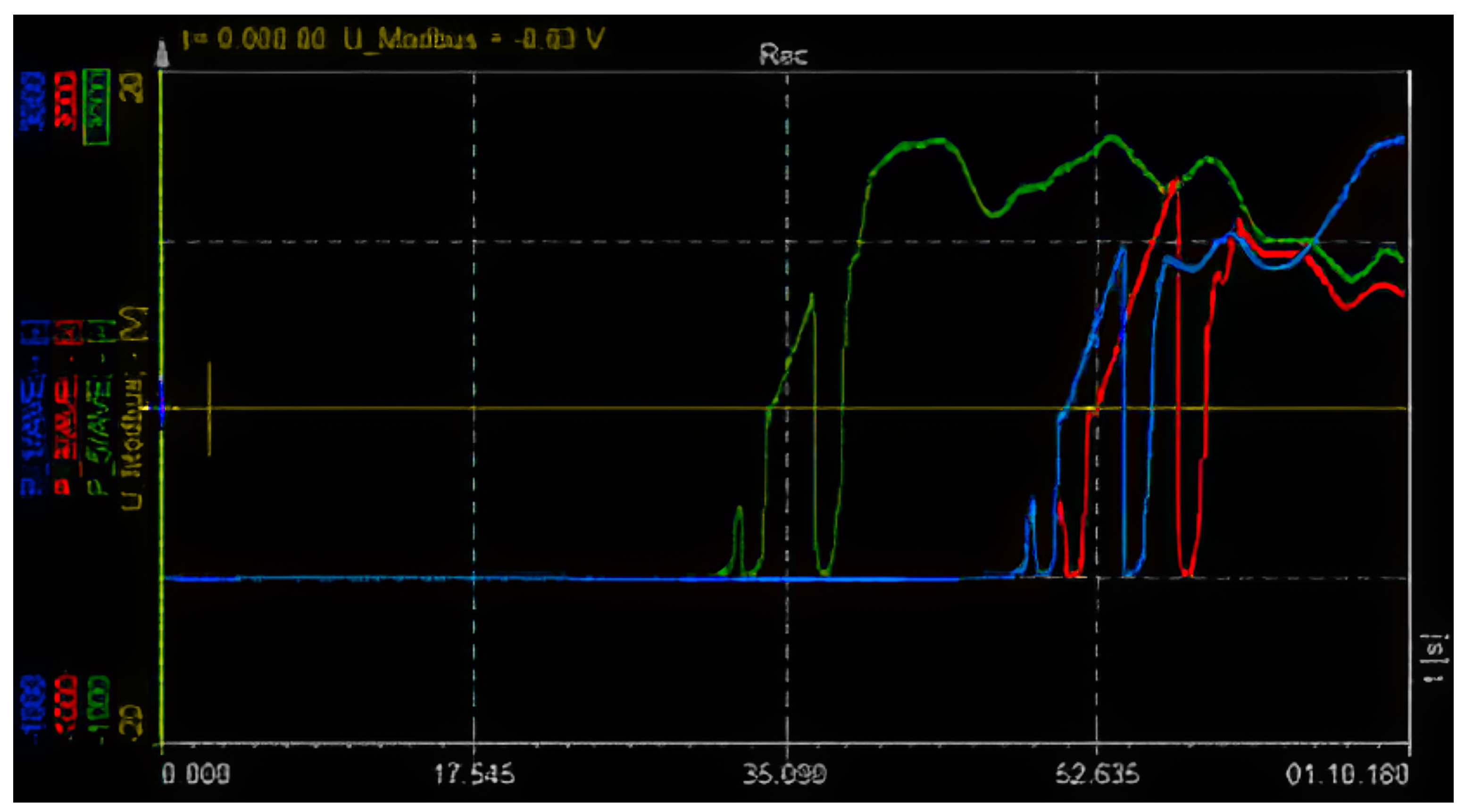
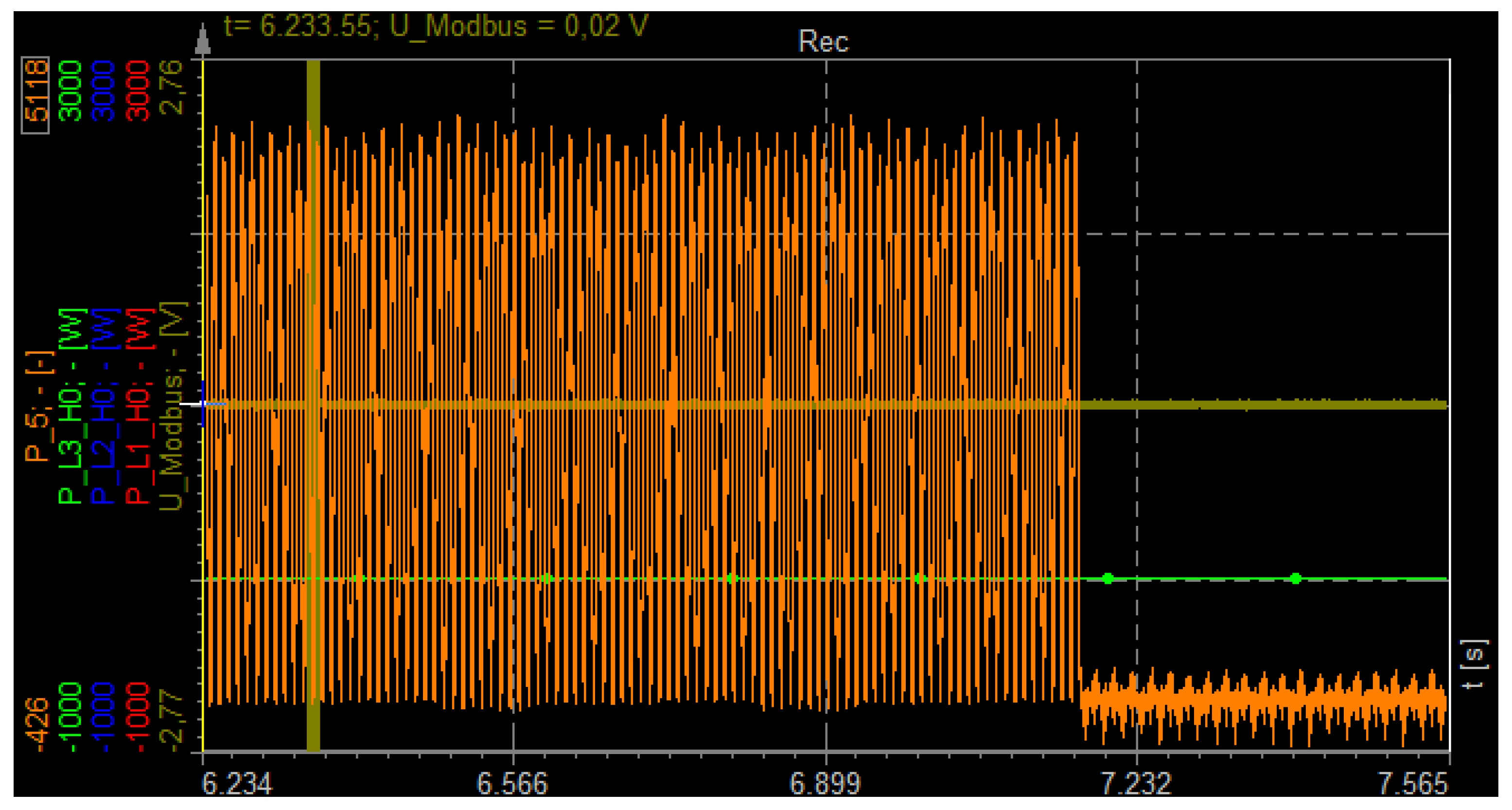
PowerLimitChanged: This scenario was used to validate the ability of the DER to remote control its AC power output. The inverter itself is remotely controlled via Modbus/TCP command; the power output is rated in steps of 1 percent of the inverter’s nominal AC output power. The power reduction according to the remote signal was measured via a Dewetron AC network analyser.
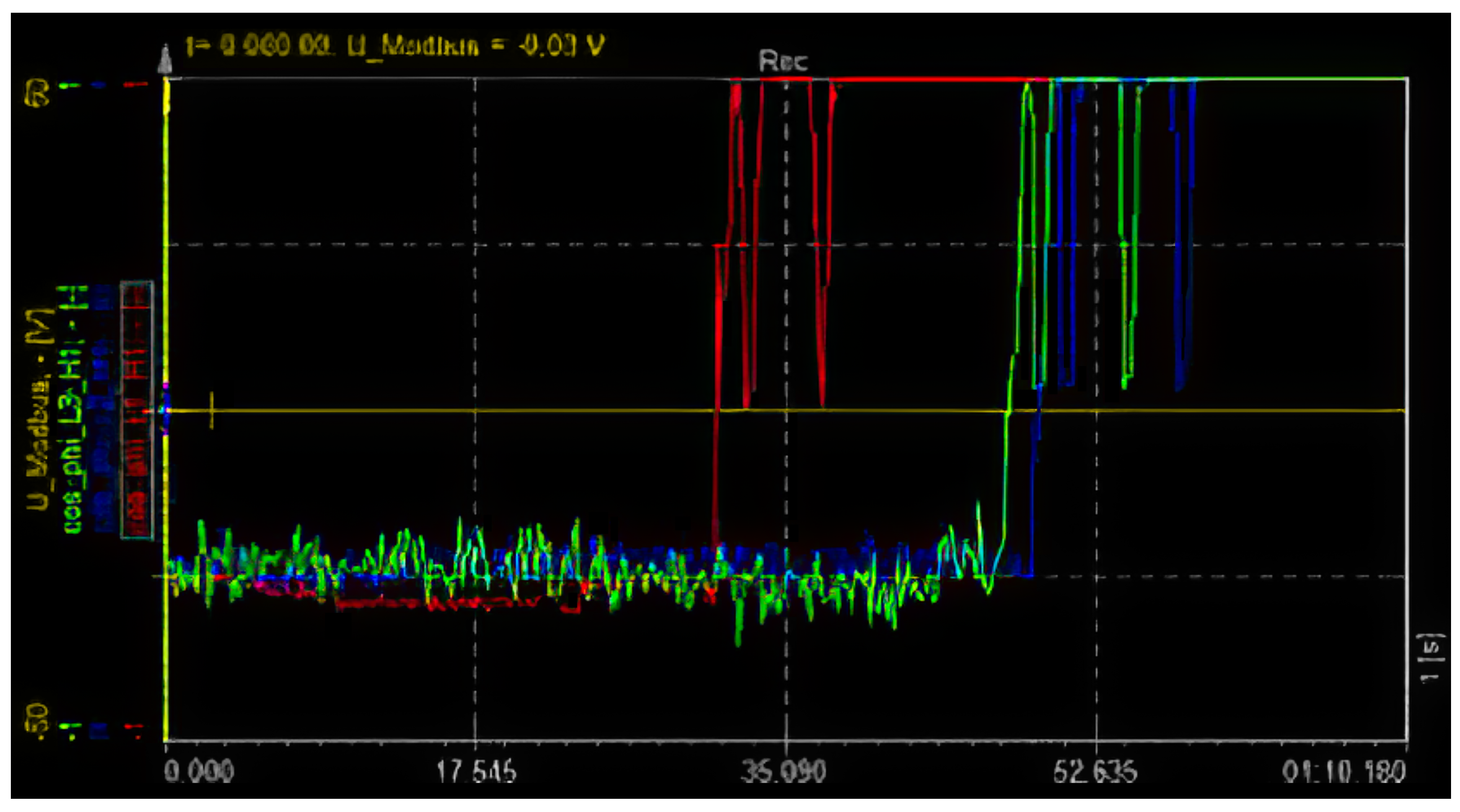
CosPhiChanged: This scenario was used to validate the ability of the DER to control its percentage distribution between active and reactive power output. The inverter itself is remotely controlled via Modbus/TCP commands; the power factor cos() is adjusted in steps of 10-2 between its lower and upper limits. The cos() delimitation according to the remote signal was again measured via the Dewetron AC network analyser.
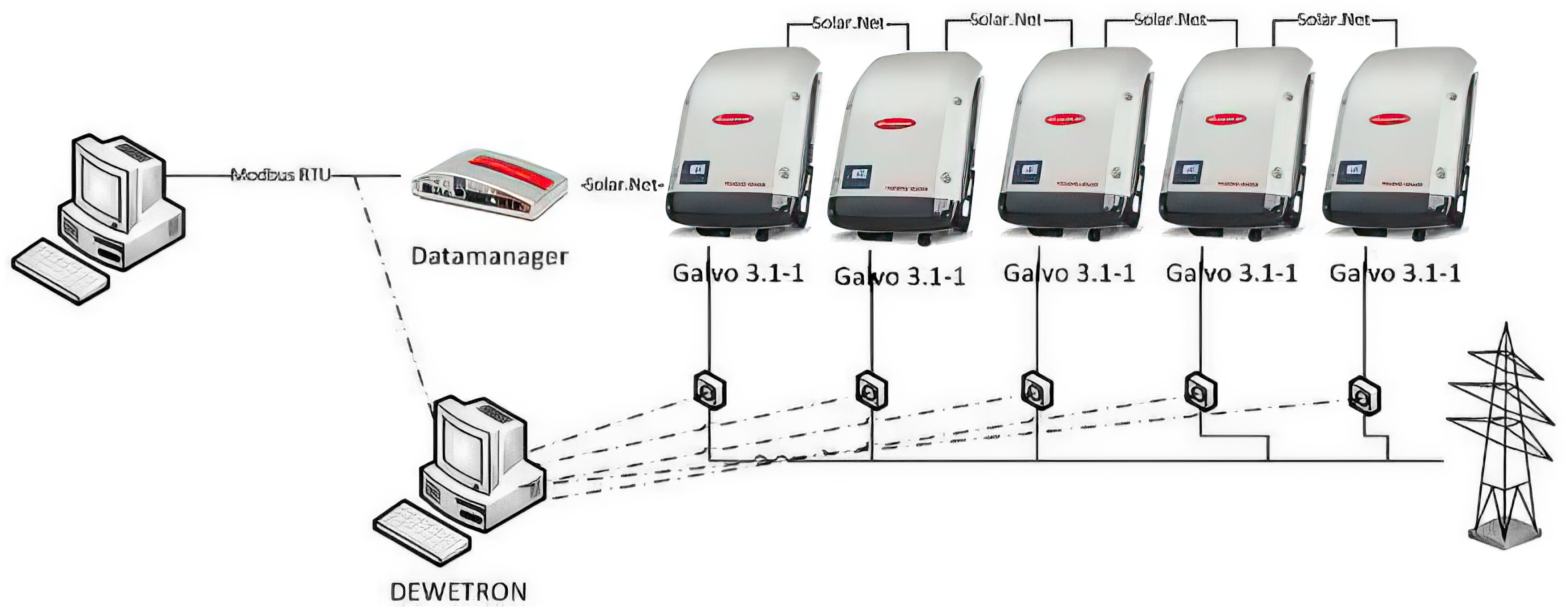
Figure 10 provides an overview of the realised test setup for validating the basic DER services using 5 solar inverters connected to the Fronius datamanager box (DM-Box) controller equipped with the SmartOS-compliant prototype.
The solar inverters have been remotely controlled via Sunspec/Modbus messages. The time difference between Modbus signal and the reaction of the inverters was measured. Remote commands used for this experiment were startup and shutdown commands, as well as power reduction and cos(
) variation. In
Figure 11,
Figure 12 and
Figure 13 and
Table 1 and
Table 2, the startup and shutdown measurements are provided along with the key characteristics.
In summary, it can be said that this validation scenario has successfully proven that the remote control of DER services enables direct influence of the grid environment. It should be noted that inverter-based DER units (in this scenario, conjoined PV inverters) controlled remotely via SCADA can stabilise, but also destabilise, the energy grid. The use of such functionality must, therefore, be strictly controlled and performed with great care in order to avoid disturbances of the energy grid.
6.2. Generic and Interoperable Communication
For the communication part of the proof-of-concept validation, the requirements have been identified as follows:
VR2-1: Ensure internal communication of applications,
VR2-2: Ensure communication of applications on different systems (i.e., IEDs)),
VR2-3: Ensure security (especially confidentiality and integrity) of external communication,
VR2-4: Ensure authentication methods and role-based rights management,
VR2-5: Ensure interoperability with legacy devices (e.g., over Modbus),
VR2-6: Ensure the seamless cooperation with high level engineering concepts, and
VR2-7: Ensure flexibility and configurability of the communication subsystem.
The requirements VR2-3 and VR2-4 show that the request for integrating security means has been fulfilled appropriately. The approach here was to integrate security already by design, as described in Reference [
5], to allow for the consideration of security related functionalities in the engineering process. As will be demonstrated, an appropriate realisation thereof has been developed as well.
Configuration of all communication related parameters (VR2-7) had to be done manually throughout the proof-of-concept validation. This concerns all sub-scenarios listed below. For obtaining the necessary test results, this is sufficient. For commercial solutions, a more practicable way of configuring the communication subsystem should of course be chosen.
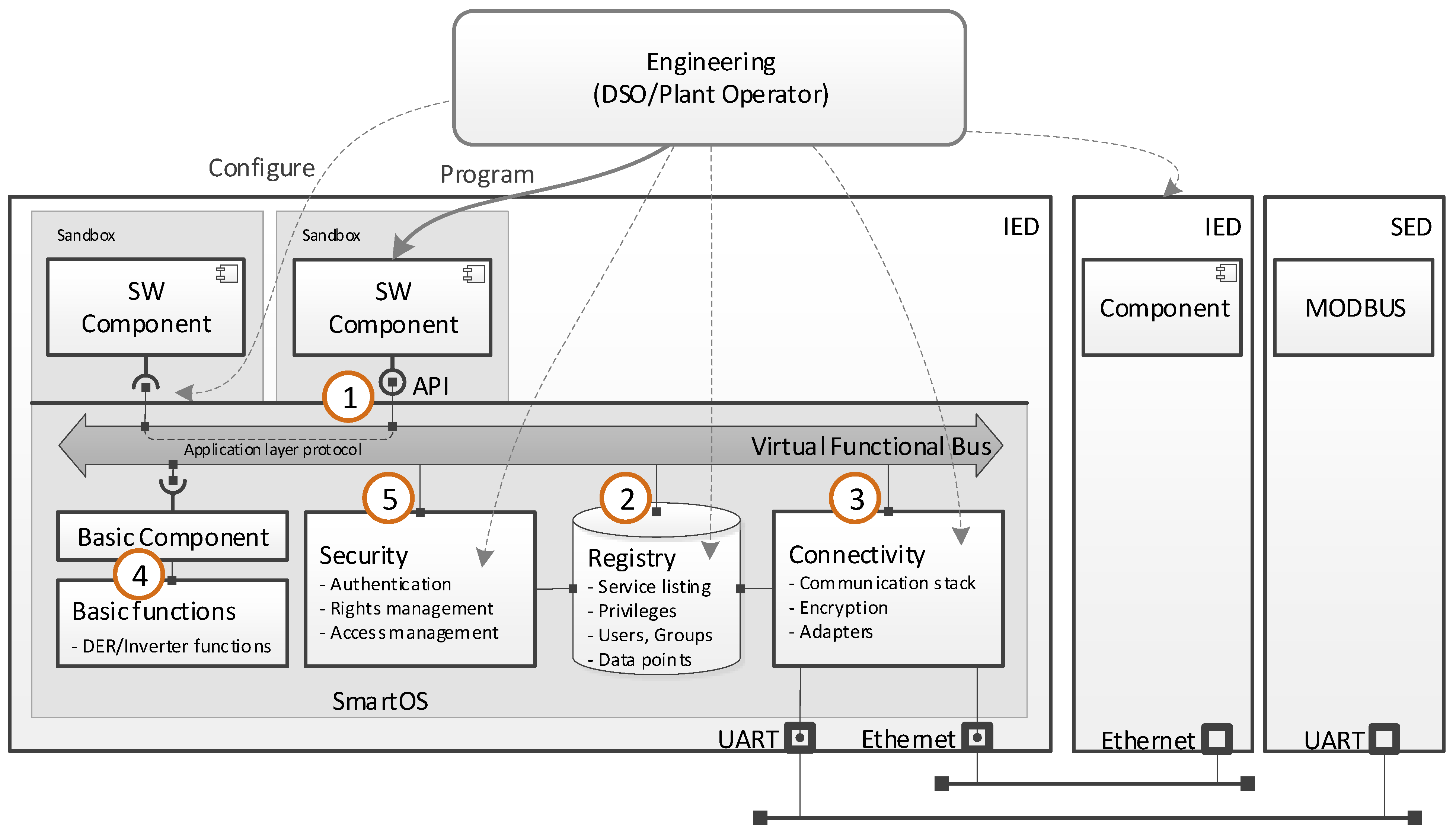
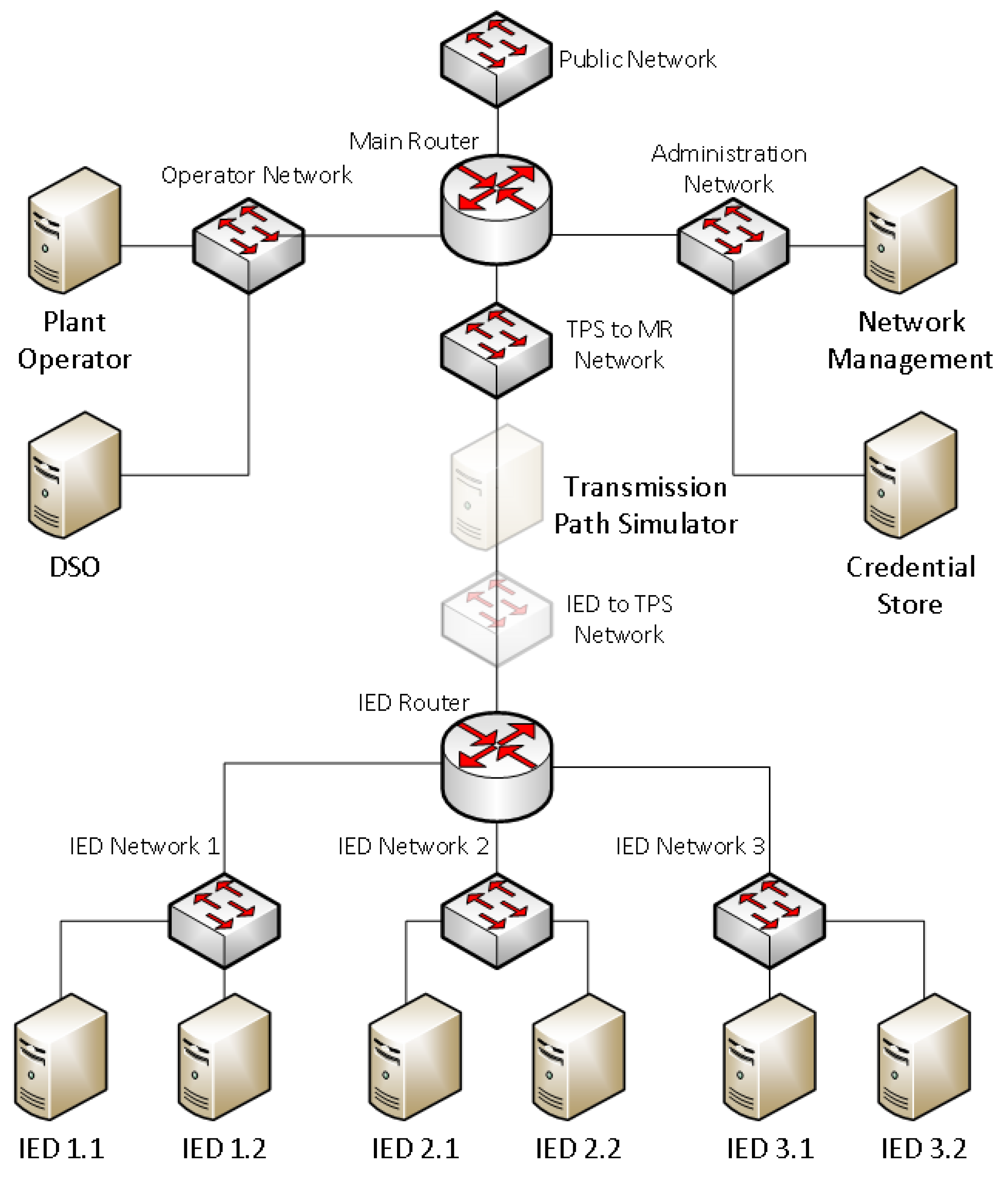
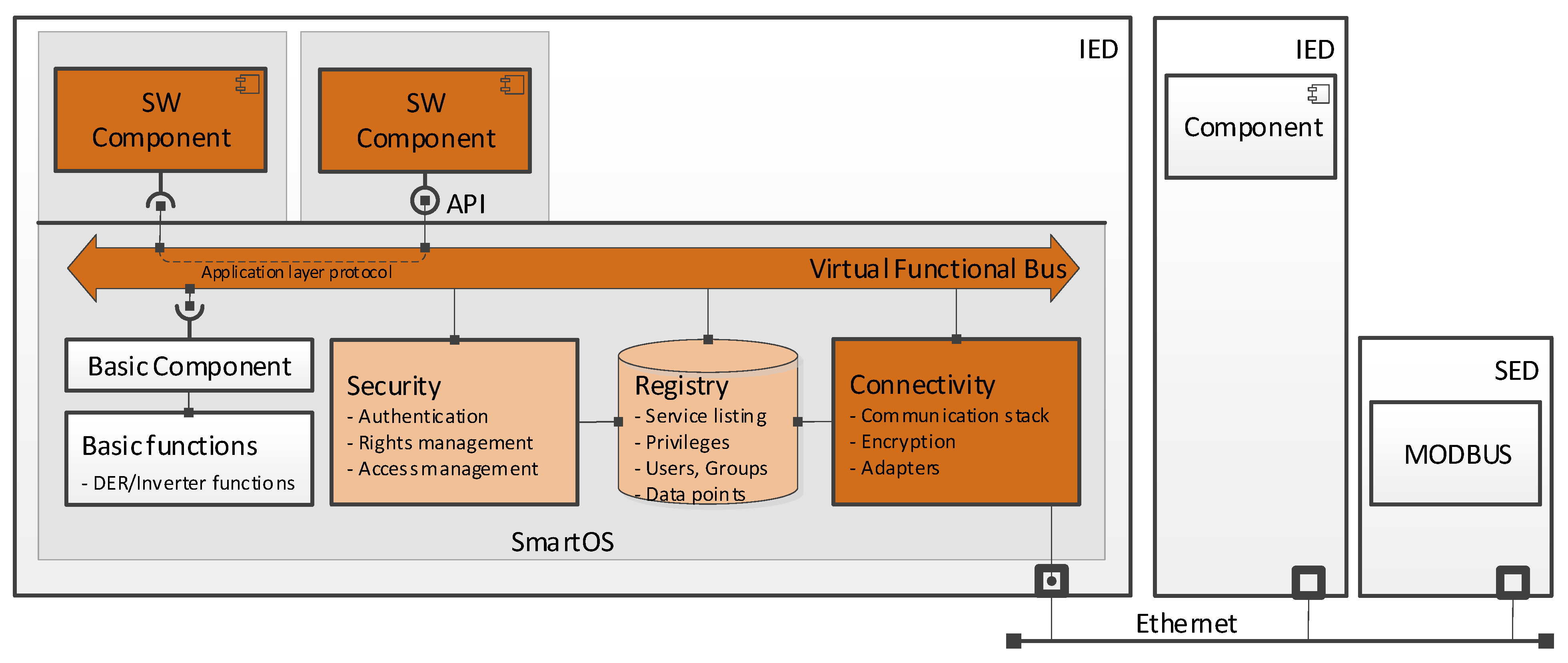
The goal of this validation scenario is to demonstrate the functionality of the modular communication system which has been previously specified and realised. This necessitates a series of tests in order to involve all relevant components of the SmartOS. An overview of the involved components is given in
Figure 14, where directly involved components are coloured orange, and indirectly involved components are coloured light orange.
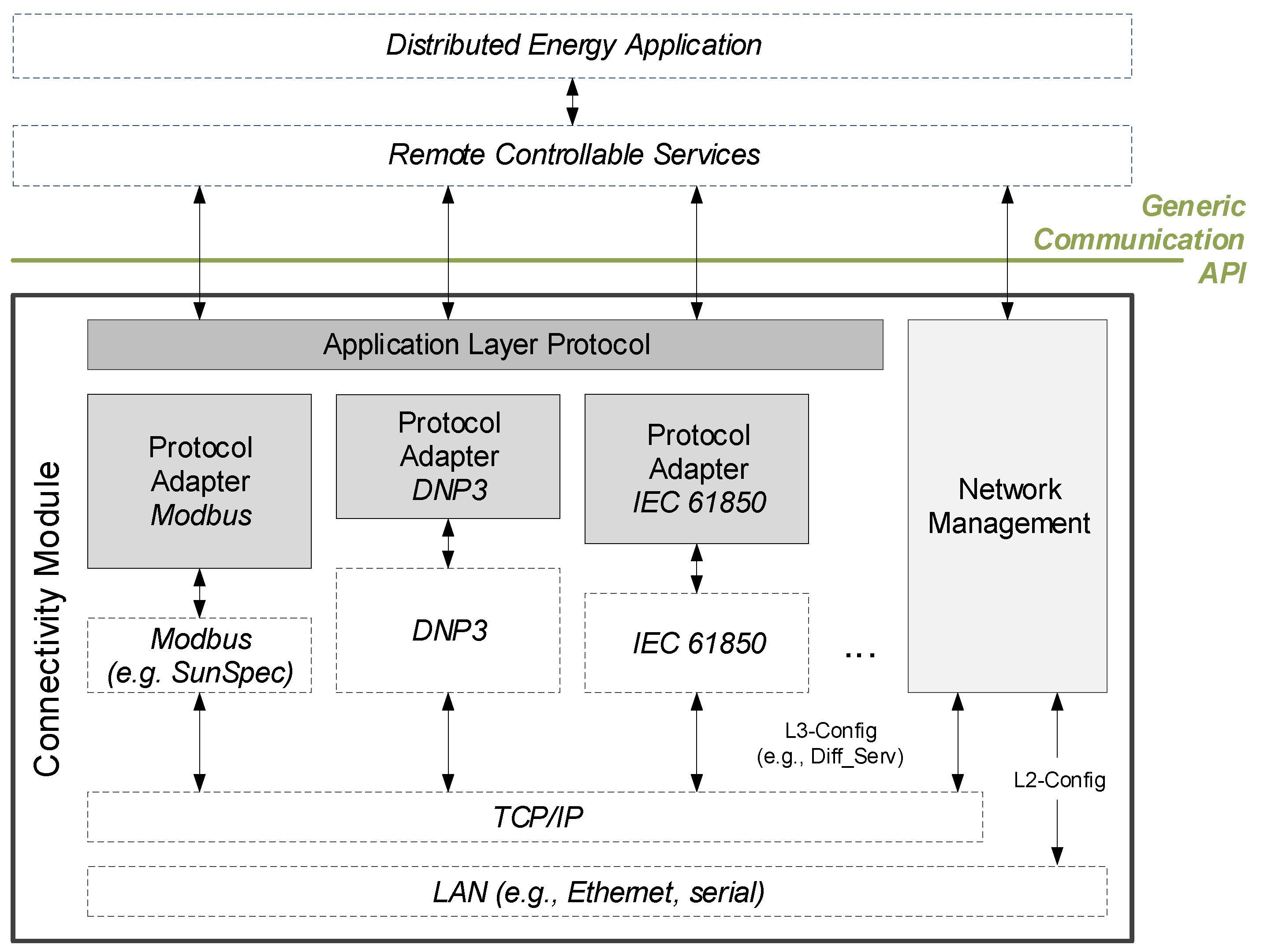
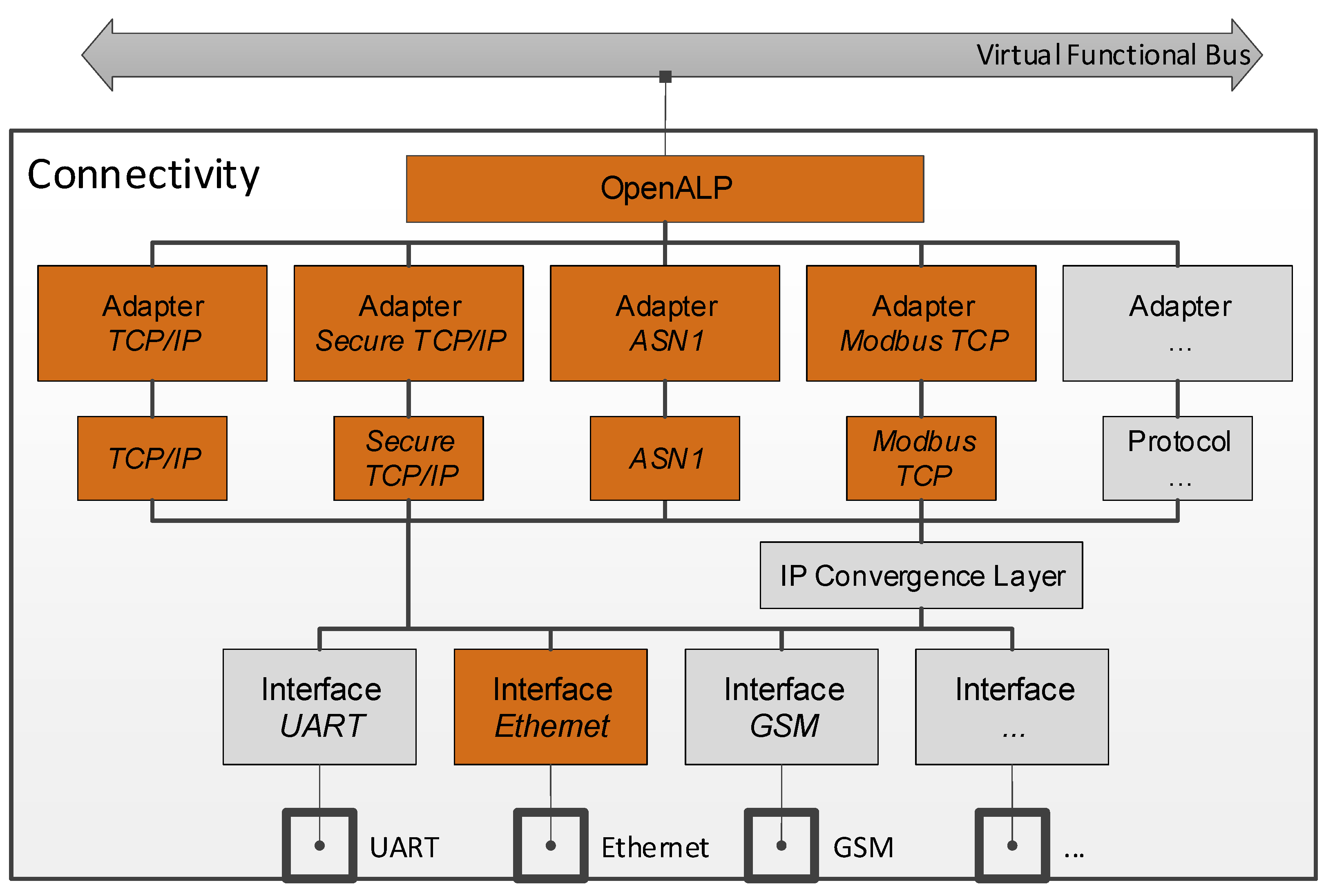
Furthermore, an overview of the tested adapters and protocols, which are implemented as a part of the connectivity module, is provided in
Figure 15. In order to allow incoming traffic for TCP/IP, secure TCP/IP and abstract syntax notation one (ASN.1), server modules are used. For Modbus, this has been omitted because the SmartOS only acts as a Modbus master in the conducted tests.
For this scenario, a series of increasingly complex tests has been devised, which have been designed to gradually increase and/or broaden the amount of components involved with each successive test. This keeps the amount of (added) complexity for each test case manageable, yet it allows for a systematic test of the entire communication system and a demonstration of its generic and interoperable nature. The scenarios are as follows:
- (a)
Two software components communicating locally: This minimal test demonstrates the basic functionality of the VFB and OpenALP, as well as the security and registry subsystems.
- (b)
Two software components on separate IEDs communicating over TCP/IP: Extends the previous scenario to include the connectivity module and its ancillary TCP/IP adapter. In addition, the communication pattern is changed from a push message to a request and the accompanying response.
- (c)
Two software components on separate IEDs communicating over ASN.1: This shows the transparency and interchangeability of the underlying protocol.
- (d)
Two software components on separate IEDs communicating over secure TCP/IP: This extends the scope of scenarios b) and c) to include encryption and authentication (the latter utilising the trust centre). Furthermore, it can be shown that certificate revocation prevents a device from connecting to other devices.
- (e)
A software component communicating with a legacy device via Modbus/TCP: Further demonstrates the transparency and interchangeability of the underlying protocol, as well as the support for legacy devices.
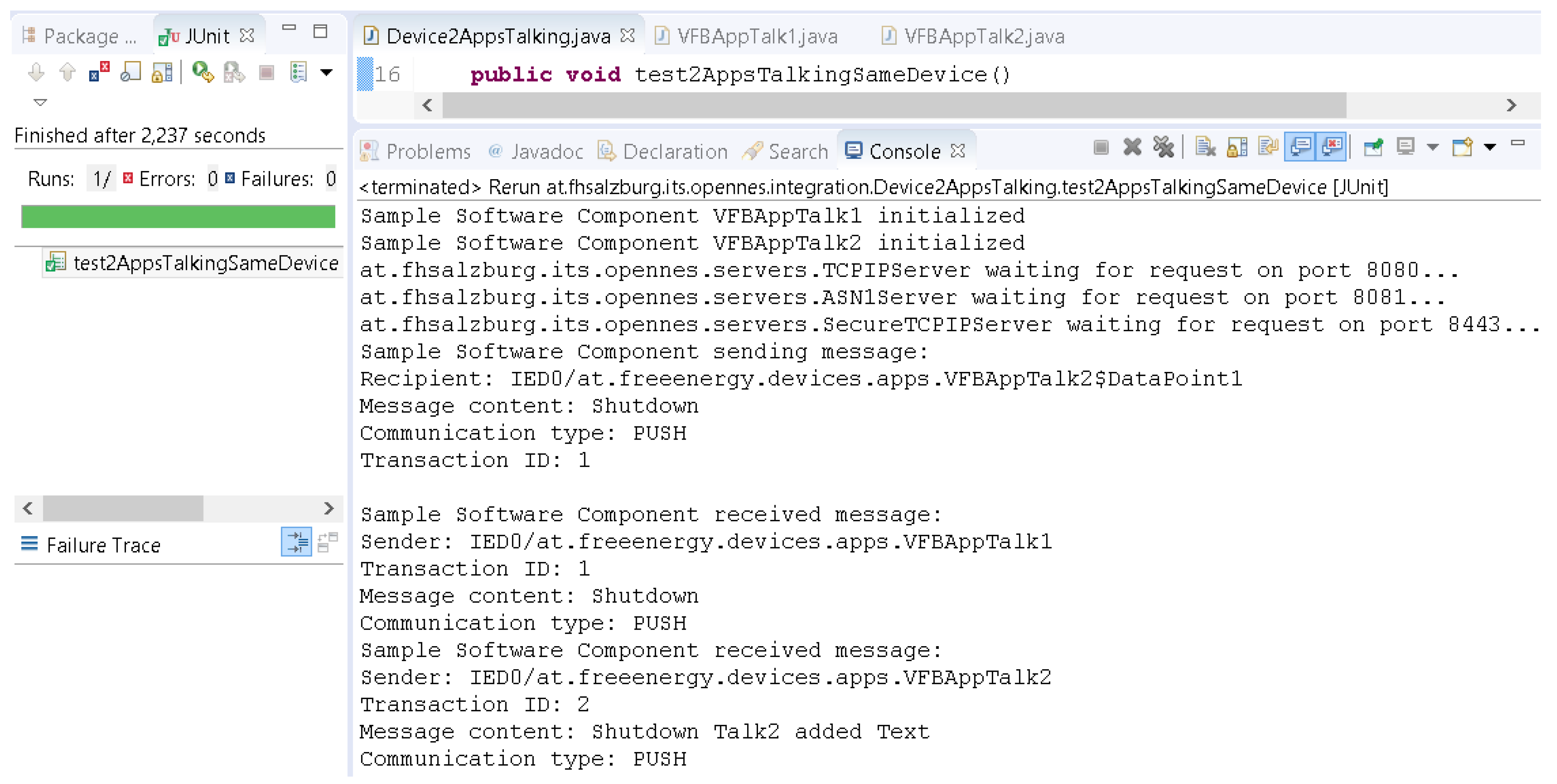
The environment for these scenarios comprises a series of tests spanning one or more projects in the Eclipse integrated development environment (IDE). It is complemented by VPN access to the virtual testing environment, which hosts required services, such as the credential store. For test (e), a software-based Modbus slave has been created containing a process image from which data can be read and to which data can be written by a software component. Tests with a physical Modbus slave device have also been successfully performed and have yielded similar results. For test (a), a JUnit test invokes two software components (VFBAppTalk1 and VFBAppTalk2) running on the same IED. Upon initialisation, VFBAppTalk1 sends a push message to VFBAppTalk2. The successful completion of the test is confirmed via JUnit and console output, as can be seen in
Figure 16.
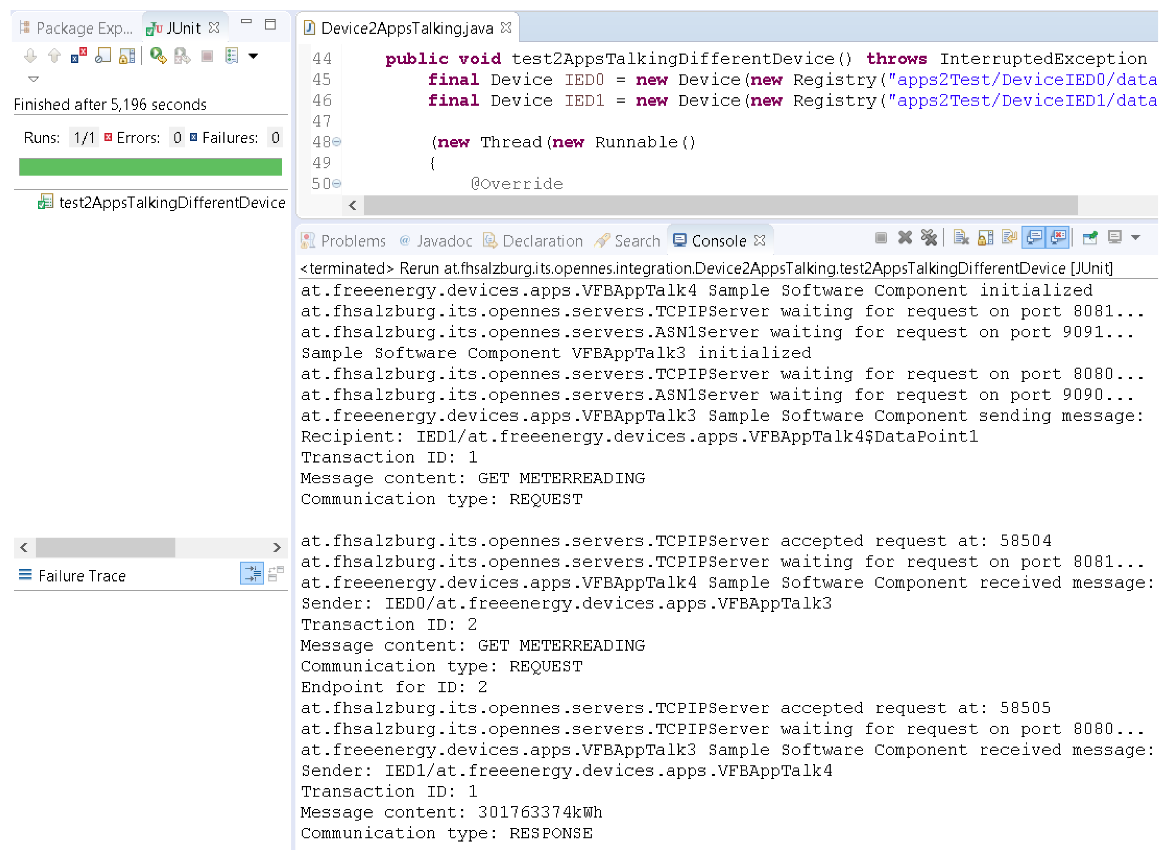
For test (b), a JUnit test invokes 2 software components (VFBAppTalk3 and 4) on 2 logically separate IEDs (hosted physically on the same machine). Upon initialisation, VFBAppTalk3 sends a request message (a simulated meter reading) to VFBAppTalk4, which then returns the appropriate response (a random integer). The successful completion of the test is confirmed via JUnit and console output, as can be seen in
Figure 17.
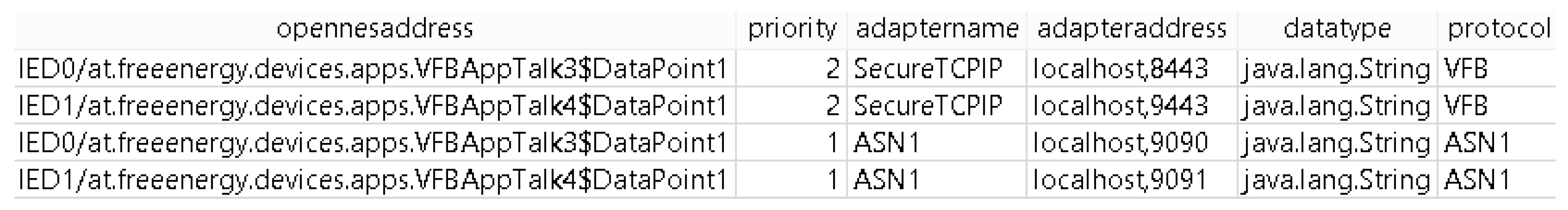
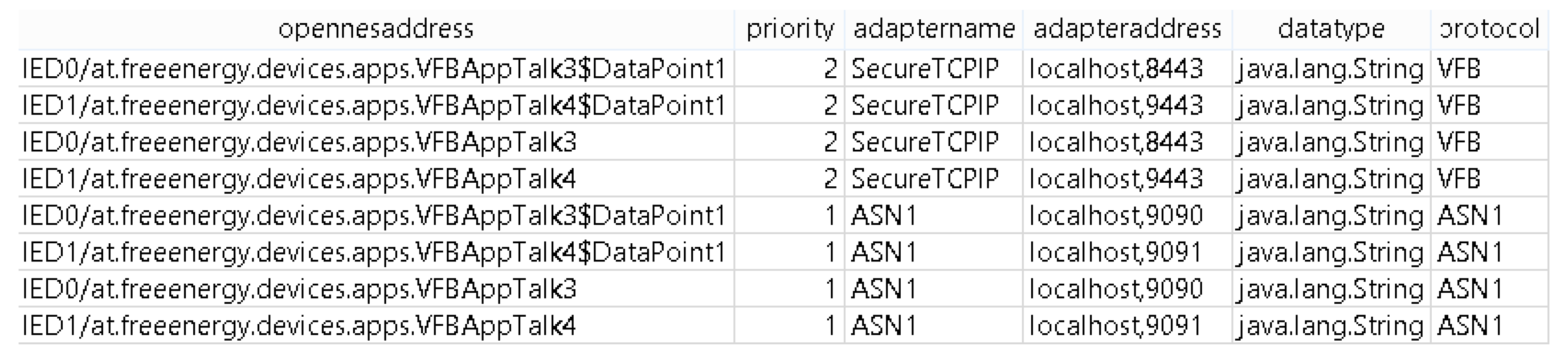
Test (c) uses an identical setup to test (b), but with a modified device configuration which prioritises ASN.1 instead of TCP/IP. The modified mapping tables are provided in
Figure 18 and
Figure 19 and the successful completion of the test is again confirmed via JUnit and console output.
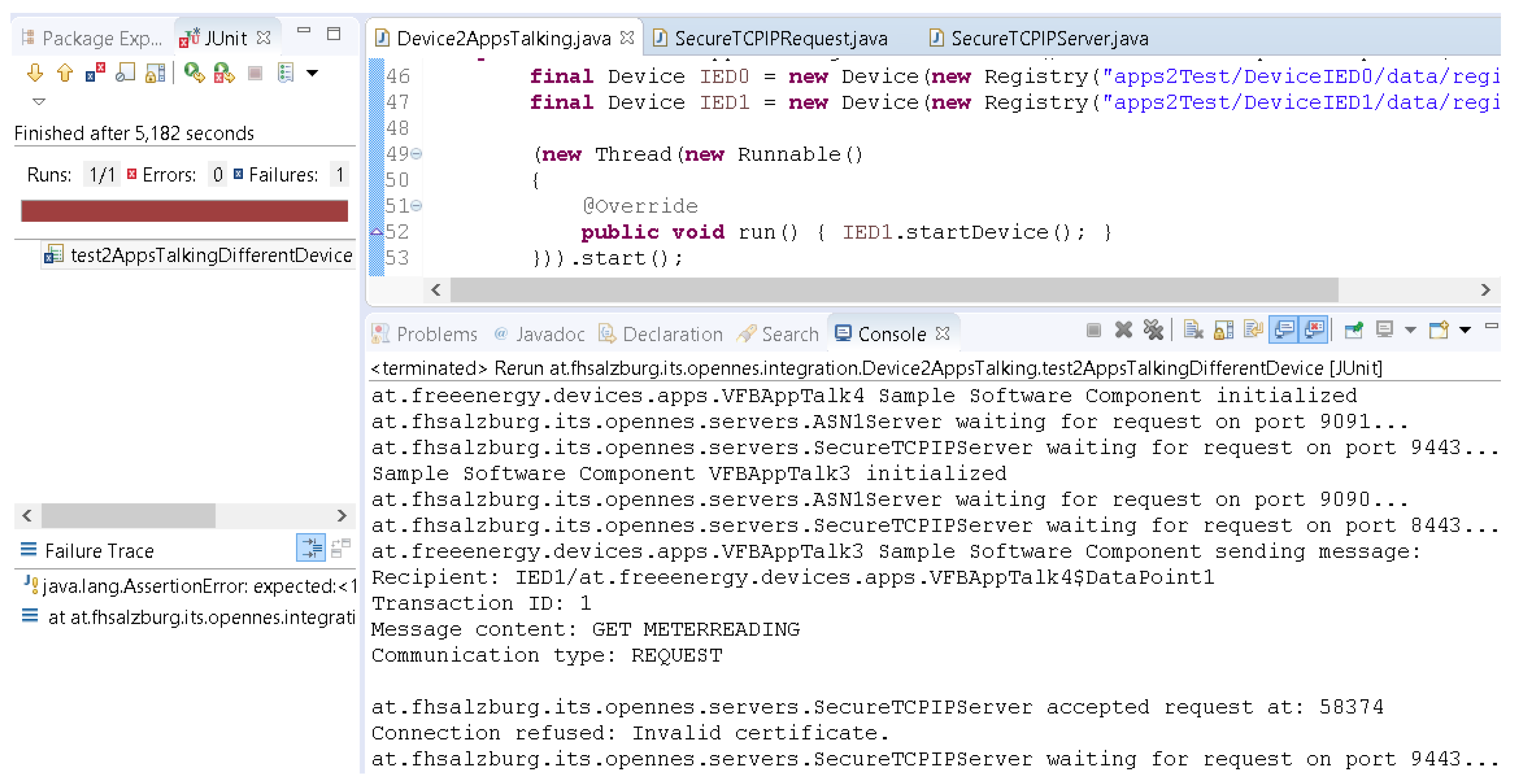
Test (d) again uses an identical setup to tests (b) and (c) and the device configuration has again been modified to prioritise secure TCP/IP. First, valid certificates are used and the test is successfully completed. Thereafter, the certificate used on IED0 is revoked on the trust centre. As a result, the incoming request is refused by IED1, and the unit test fails (see
Figure 20), which, in this case, is the expected and desired result.
For test (e), the Modbus library Modbus4J has been utilised to provide a Modbus slave containing a process image from which data can be read and to which data can be written. Thereafter, a software component (SimpleVFBApp3) has been created to send a series of messages to the Modbus slave, and the device registry on the IED running SimpleVFBApp3 has been configured to provide the address and data point of the Modbus slave as IED4/sampleNamespace$SampleModbusValue. Upon initialisation of the IED, SimpleVFBApp3 is invoked and sequentially performs three tasks: First, a request message is sent to read the value of the aforementioned data point. Second, a push message is sent to set a different value for this data point. Last, a request message is sent once again to confirm that the value has indeed been set. The successful completion of the test is again confirmed via JUnit and console output.
Summarising this scenario, it can be said that all tests could be completed successfully, and the goals regarding generic and interoperable communication have been achieved. Although the tests have certainly not been as rigorous as would be required for a market-ready product, they are sufficient to validate the effectiveness of the solutions that have been developed for the critical challenges. Further work towards the creation of a final product would predominantly involve fine-tuning and optimising and is not expected to encounter any major challenges for which no well-established solutions exist.
6.3. System Integration
The requirements for the system integration test cover in principle all the above outlined requirements. However, especially for the integration testing of the proof-of-concept validation, the following additional requirements have been identified:
VR3-1: Ensure the safe and secure execution of DER services, and
VR3-2: Ensure the safe and secure execution of energy/DER applications.
The previous scenarios all resulted in successful validations of the main parts of the proposed approach: (i) the formal application modelling concept (see Reference [
7]), (ii) the remote programmable DER services, and (iii) the generic and interoperable communication. With these validations as a basis, the final scenario shows a system integration validation. In other words, the main intention is to use the application modelling approach to create and use remote DER functions with the help of the generic and modular communication system.
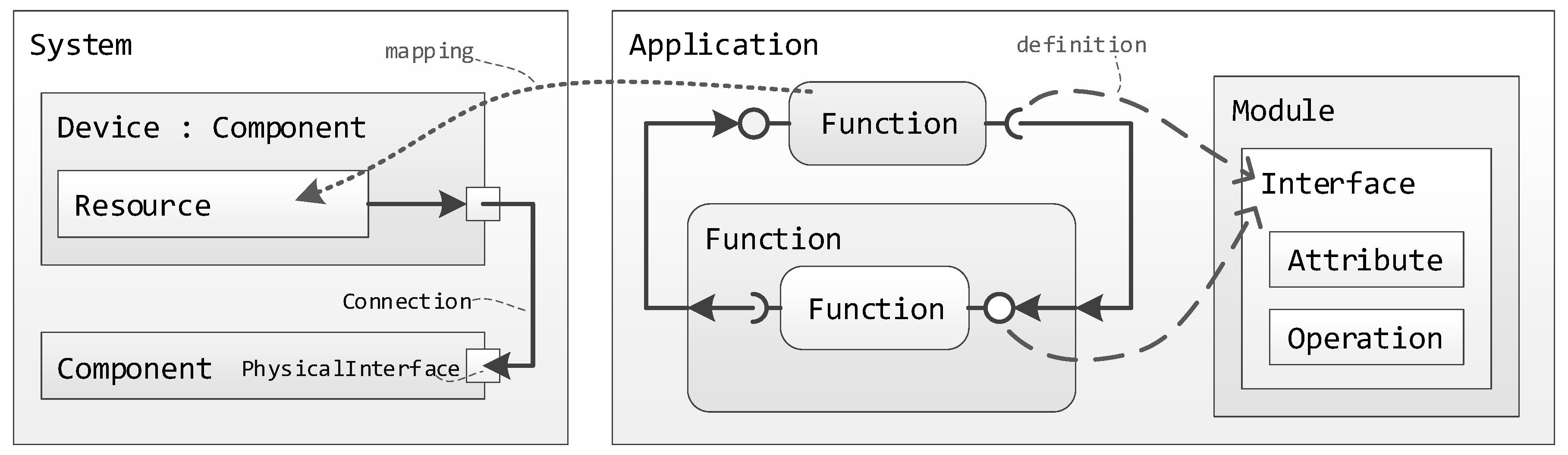
This scenario is also intended to be a validation of the overall idea of the approach, as shown in
Figure 4 and as it has also been used in Reference [
7] for the validation of the application modelling concept. It is assumed that the overall application has been modelled using the formal modelling approach. Furthermore, it is assumed that the remote programmable DER services are available and that the other components of the SmartOS are operational. The last precondition is, that it is possible to communicate between DERs using the Connectivity component (i.e., the generic and modular communication concept tested in
Section 6.2). Consequently, what is left to validate is the integration of these parts with each other. First, it has to be shown, how an application can be deployed, configured, and started on a DER device, once it has been modelled. Second, it has to be shown, how the communication between different devices can be implemented and properly configured.
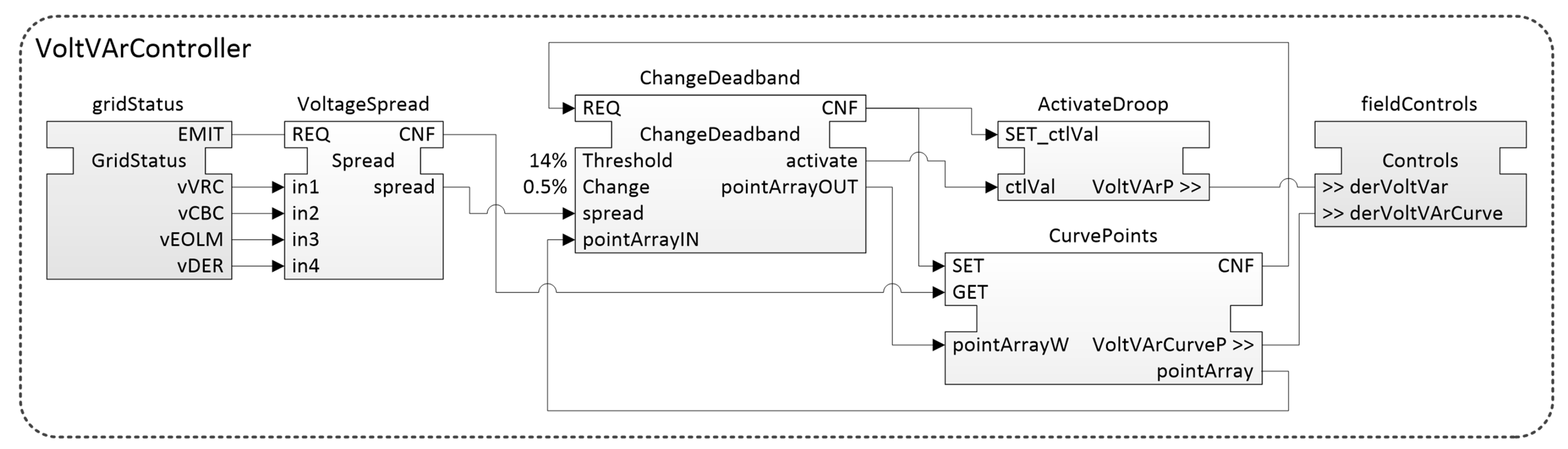
For this validation, the following test case is used: A voltage change in the grid of a distribution system operator (DSO) causes the voltage spread to increase above its allowed threshold. This causes the control algorithm in VoltVArController seen in
Figure 21 to calculate a new Volt-var droop curve for the DERController. With the new curve, the DERController will be more sensitive to voltage deviations. This, in turn, will decrease the voltage spread.
Compared to the previous scenarios, this test case shows how the envisioned method is used to deploy an application to real devices. Furthermore, it also includes communication between multiple devices using different communication protocols, which need to be configured. Finally, the goal is also to validate the implementation of the VoltVArController function as depicted in
Figure 21.
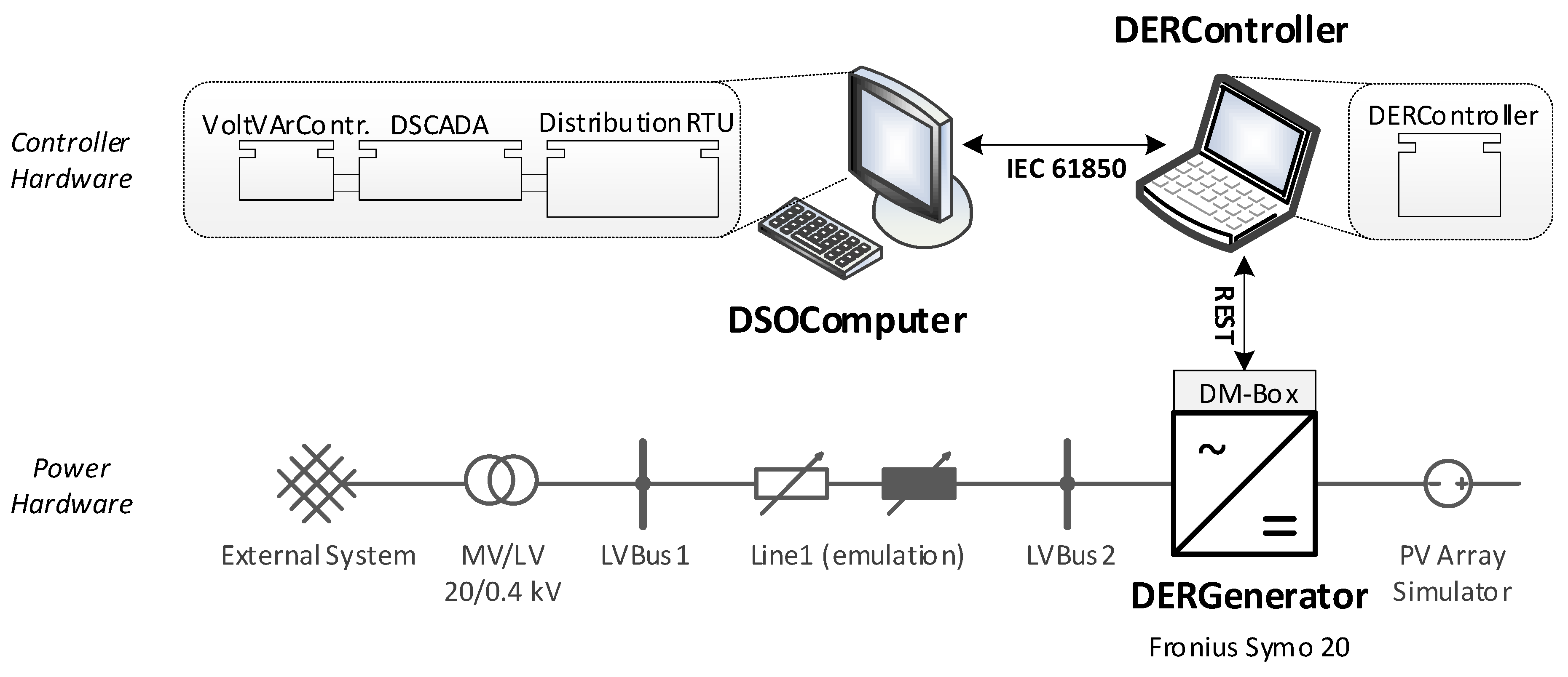
A scheme of the used parts of the AIT SmartEST lab setup is illustrated in
Figure 22. It also shows on which components the different IEC 61499 functions are deployed. The VoltVArController function, as shown in
Figure 21, is deployed on the DSOComputer.
The controller hardware used in the laboratory consists of a desktop PC representing the DSOComputer and a laptop PC running the SmartOS and the DERController App. The DERGenerator is a commercial off-the-shelf Fronius Symo 20 PV inverter; on the DC side, it is connected to a PV array simulator, and, on the AC side, to the LV grid. A line impedance had to be emulated by the laboratory equipment in order to create a dependency between the voltage and the inverter output. Natively, the inverter offers a Modbus/TCP control and measurement interface. However, for this test, a representational state transfer (REST) interface was added to facilitate communication between the inverter and the SmartOS App. On the laptop, the SmartOS was executed together with 4diac [
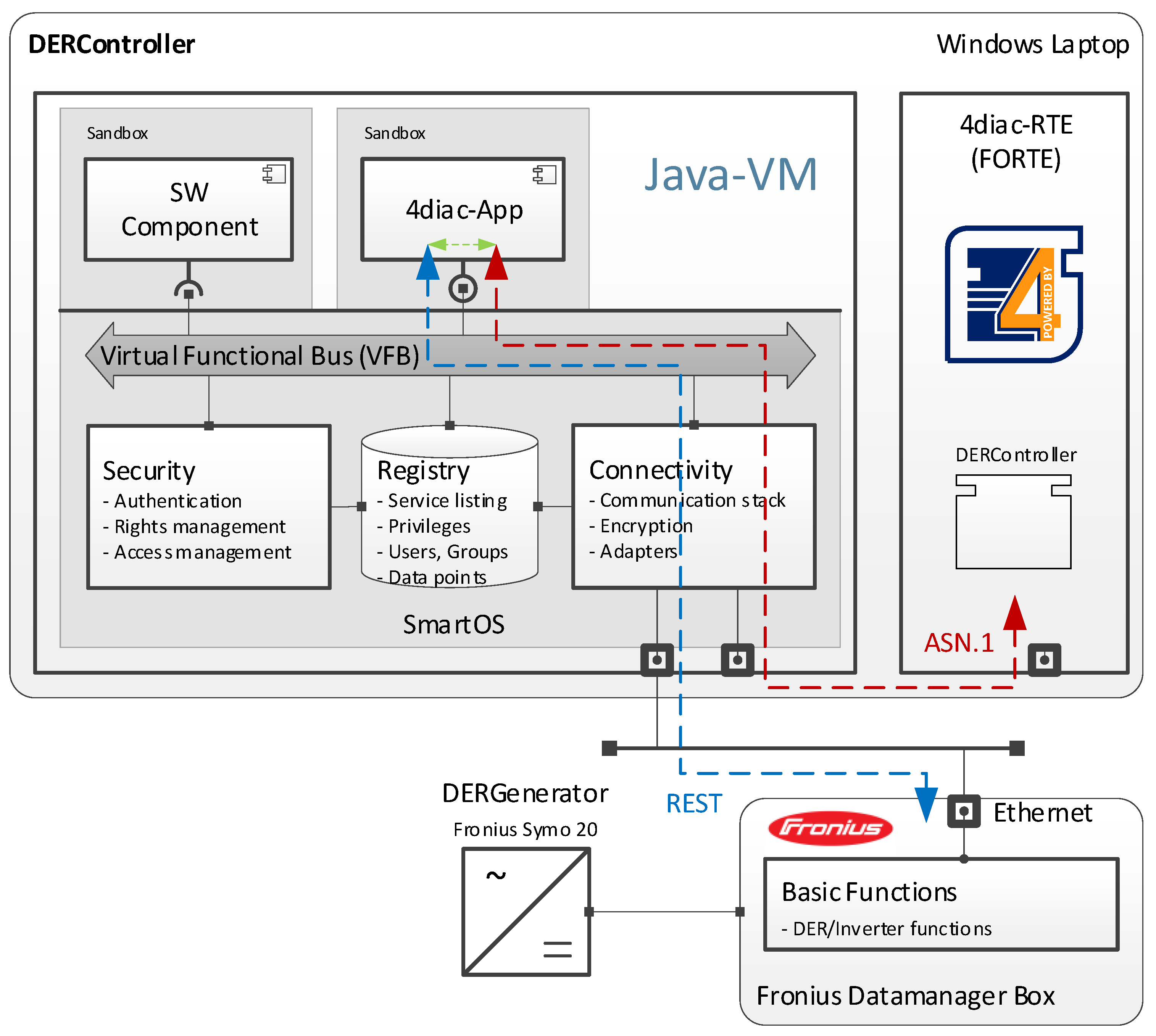
60]. The setup of the SmartOS is shown in
Figure 23.
In order to use the programmability of 4diac, it was integrated with the VFB of the SmartOS. First, an ASN.1 adapter was created for the Connectivity component. This adapter allows communication between software components and the 4diac runtime environment (FORTE). This communication is shown in
Figure 23 as a dashed red line. However, in order to change the reactive power, a command must be sent to the basic functions component running on the Fronius DM-Box. For this, the next step was to create a dedicated software component that forwards messages from the FORTE to the DM-Box. This means that, if the DERController function in the FORTE wants to send a new reactive power setpoint to the inverter, it is first sent to the 4diac-App using ASN.1 prior to being forwarded to the basic functions component using the REST protocol (represented as a dashed blue line in
Figure 23). Finally, the DM-Box makes sure that the reactive power setting is applied by the inverter-based DER.
Before the laboratory validation could be started, the application had to be deployed. The first precondition for this is that the inverter is connected and feeding power to the grid. Second, the FORTE must be executed on all the components and awaiting a deployment from the 4diac-IDE. The next step was to deploy the communication configurations.
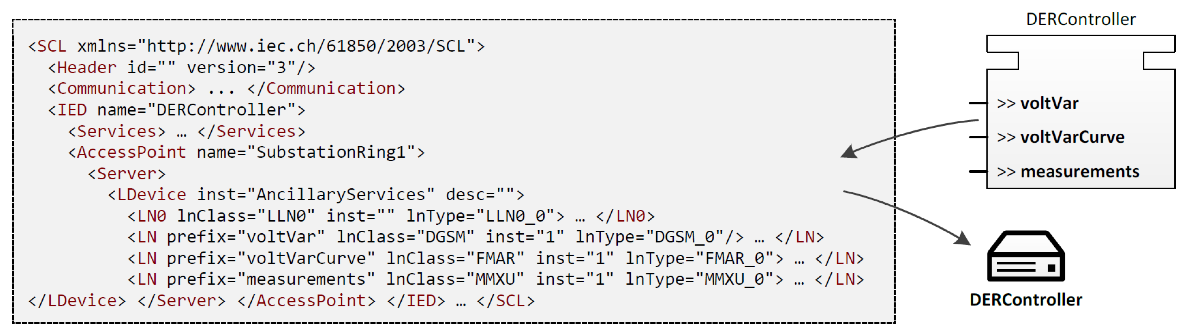
Next, the communication infrastructure was generated for connections between IEC 61499 functions running on different devices. Generated were both communication FBs, as well as communication configurations. For this test case, all the interfaces are derived from IEC 61850, which results in generation of substation configuration description language (SCL) files for the communication configuration. The resulting IEC 61850 configuration for the DERController is seen in
Figure 24. As is seen, the IEC 61850 SCL configuration adopts information from the IEC 61499 application (e.g., the IEC 61850 IED is named DERController after the IEC 61499 device).
After this, the SCL files and the IEC 61499 applications are deployed to their components according to
Figure 22. This is a built-in feature of 4diac and utilises standard IEC 61499 methods; thus, no new code has to be generated from the IEC 61499 model. After deployment completion, the application is automatically started; hereby, the SCL files are loaded and the IEC 61850 communication is initialised. For example, the IEC 61850 client in DistributionRTU connects to the IEC 61850 server on the DERController.
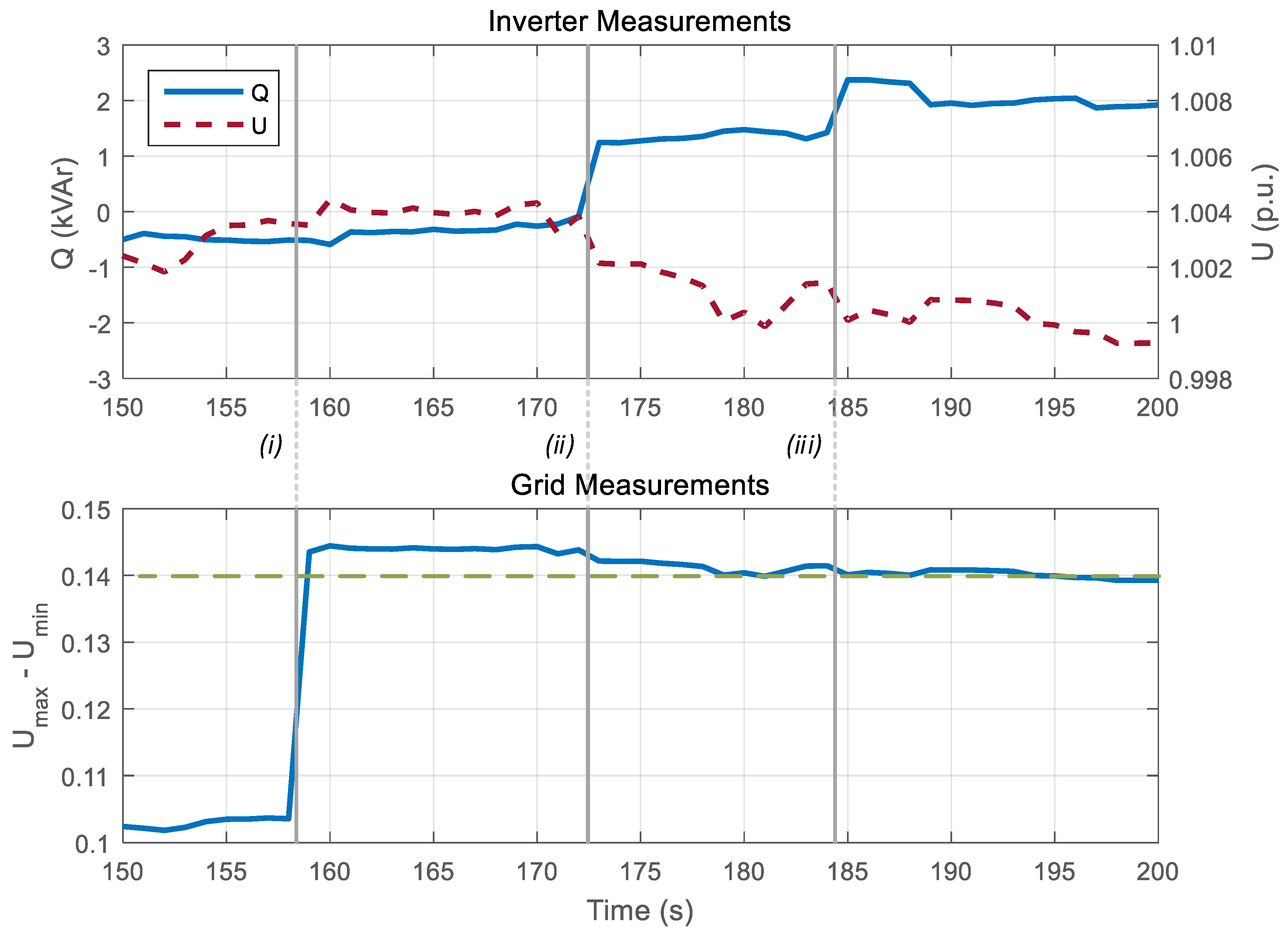
Subsequently, the VoltVArController algorithm can be validated. For this validation, the inverter is configured to an active power output of 18 kW and a reactive power output of 0 kVAr. The voltage measured by the inverter (i.e., the DERGenerator) is forwarded to the VoltVArController at the vDER data output of the gridStatus FB (see
Figure 21). The other voltage measurements (i.e., vVRC, vCBC, and cEOLM) are all emulated and fixed to 0.9 per unit (p.u.). After stabilisation, this results in a vDER voltage of around 1.004 p.u., and no extra reactive power. This is seen at the beginning of the time series in the top graph of
Figure 25, where Q is the reactive power of the inverter, and U is the measured voltage by the inverter (i.e., vDER).
An increased voltage spread was emulated to trigger the VoltVArController algorithm, seen as the first event
(i) in
Figure 25. At this event, the fixed voltage of vVRC was changed from 0.9 p.u. to 0.86 p.u. This increases the voltage spread (Umax – Umin, see
Figure 25) above the allowed threshold. This is detected by the VoltVArController’s algorithm. New Volt/var curve parameters are calculated by the ChangeDeadband FB in
Figure 21. The new curve parameters are sent to the DERController, which results in a new reactive power set point for the DERGenerator. With the new Volt/var parameters, the inverter starts producing reactive power. This is shown as event
(ii) in
Figure 25. However, since the voltage spread is still too high, a second correction of the Volt/var parameters is performed by the VoltVArController after 185 s, which is visualised in
Figure 25 as event
(iii).
In general, the results of this experiment indicate a successful integration of the different parts of the proposed approach. This scenario shows that even with the prototypical implementation, it is possible to achieve an open and interoperable ICT solution for the integration of DERs. For productive use, many adjustments would of course have to be made to the setup shown in
Figure 22 (such as running the SmartOS on the DM-Box and integrating the FORTE into the 4diac App).
Regarding the results of the test, especially the measurements shown in
Figure 25, more evidence of the prototypical nature of the implementation is seen. In an industrial implementation, these changes would have to be in the range of milliseconds, whereas they are in the range of seconds in this case. This can be explained by the suboptimal test setup shown in
Figure 22, as well as a complete absence of code optimisation in that regard. Nevertheless, the results demonstrate the basic usefulness of the presented concept. For industrial adoption, the reaction time has yet to be improved to the required level.
6.4. Reflection of Results
The achieved results show that the proposed architecture helps to fill the gaps of current solutions and approaches, as identified in
Section 2.4, in the following way:
As outlined in
Section 3.4 and further explained in Reference [
7], this work provides an approach for a common application modelling concept for power and energy systems automation applications.
By supporting a wide range of communication protocols, the developed architecture provides a unifying method of integrating renewable energy sources into smart grids. It allows to build open and scalable smart grid automation applications in a hardware and platform independent way.
The introduction of RCSs makes it possible to reuse common functionalities and to update and extend DER services across the entire lifecycle of DER components.
The specific system performance and level of compliance to timing requirements will depend on code optimisation, as well as the underlying protocols. It will, therefore, be need to be analysed on a case-by-case basis, if given requirements can be met using given protocols.
For real-world solutions, safe handling of potential controller conflicts is an essential requirement. An approach to a potential solution is provided in Reference [
61].
Although cyber-security issues have not been the primary focus of the work at hand, security-by-design principles as outlined in Reference [
5] have been applied during the development of the architecture, resulting in a fundamentally robust system. As our solution aims for a maximum of protocol independence, the integration of a more comprehensive security architecture is easily possible if needed.
The proposed architecture and proof-of-concept prototype is currently being further developed into an industry grade solution. This entails, among other things, the addition of support for additional protocols and the realisation of a fully-fledged trust centre/credential store, as well as code optimisation. Prior to its roll-out and use in real-world scenarios, it will further have to undergo extensive testing (conformity, security/penetration, deployment and acceptance tests, etc.).


 ,
, 


