Article

High-Gain Vivaldi Antenna with Wide Bandwidth Characteristics for 5G Mobile and Ku-Band Radar Applications

1
Telecommunication Engineering Department, University of Engineering and Technology Mardan, Mardan 23200, Pakistan
2
Department of Electrical Engineering, University of Quebec, Val d’Or, QC J9P 1Y3, Canada
3
Communication and Wave Propagation Laboratory, Department of Information and Communication Engineering, Chosun University, Gwangju 61452, Korea
4
Center of Intelligent Acoustics and Immersive Communications, Northwestern Polytechnical University, Xi’an 710072, China
*
Author to whom correspondence should be addressed.
Electronics 2021, 10(6), 667; https://doi.org/10.3390/electronics10060667
Submission received: 1 December 2020 / Accepted: 16 December 2020 / Published: 12 March 2021
(This article belongs to the Section Microwave and Wireless Communications)

Abstract

:
In this paper, antipodal Vivaldi antenna is designed for 5th generation (5G) mobile communication and Ku-band applications. The proposed designed has three layers. The upper layer consists of eight-element array of split-shaped leaf structures, which is fed by a 1-to-8 power divider network. Middle layer is a substrate made of Rogers 5880. The bottom layer consists of truncated ground and shorter mirror-image split leaf structures. The overall size of the designed antenna is confined significantly to 33.31 × 54.96 × 0.787 (volume in mm 3 ), which is equivalent to 2 λ o × 3.3 λ o × 0.05 λ o ( λ o is free-space wavelength at 18 GHz). Proposed eight elements antenna is multi-band in nature covering Ku-bands (14.44–20.98 GHz), two millimeter wave (mmW) bands i.e., 24.34–29 GHz and 33–40 GHz, which are candidate frequency bands for 5G communications. The Ku-Band is suitable for radar applications. Proposed eight elements antenna is very efficient and has stable gain for 5G mobile communication and Ku-band applications. The simulation results are experimentally validated by testing the fabricated prototypes of the proposed design.

1. Introduction

The cellular communication system is the backbone of wireless communication and is widely used for transmission of data in the form of voices, images, and videos between users. The first generation called analogue systems have been evolved to second generation called digital systems. For the purpose of transmission of multimedia, third generation was introduced. By the introduction of high speed packet access (HSPA) and long term evolution (LTE) advanced, third generation (3G) is evolved to fourth generation (4G). The antenna systems and new technologies for designing antennas have also been developed and advanced in parallel with the evolution of mobile systems [1]. The current 4G system has been saturated because of limited bandwidth [2]. It is essential to improve the performance of the mobile network in terms of capacity to fulfill the future requirements of high-speed mobile networks [3,4,5,6,7]. Fifth generation (5G) is preferred over 4G owing to the availability of wide bandwidth which enhances network performance. Due to wider bandwidth, high volume data can be transferred in the form of tens of megabits per second (Mbps) to thousands of users simultaneously [8]. It reduces power consumption and provides improved spectral efficiency and enhanced coverage [9]. The usage of millimeter wave (mm wave) will improve the quality of the wireless communication system [10,11,12]. The 5G communication technology can provide many advantages due to its wider bandwidth, such as higher transmission rate, shorter latency, and higher capacity, over the current 4G system [13,14].
After every ten years, a progressive change is experienced in mobile technology. Every new generation has brought improvement according to needs. The major factor is the need for high data rate which is experienced in the last ten years. A data rate of 15.4 Mbps will be required per subscriber using mobile phone which can support a very high resolution video (4K) having 4096 × 2160 pixels [15]. This will enhance the video resolution, however, it will require a wider bandwidth [15]. The demand for access of bandwidth has been increased due to live streaming of watching videos for a long time by the users. The expected rise in traffic annually will reach to 291.8 exabytes (10 18 bytes) in near future [16]. Higher propagation losses are occurring in 5G mobile communications because wavelengths of mm waves are too short and have higher carrier frequency [17,18,19]. The short wavelengths are helpful in designing array antenna of many elements for obtaining high gain because small size of antenna is required for mm wave [20]. To minimize propagation losses, an antenna of stable radiation pattern, wideband, and high gain will be required. These goals can be achieved by employing Vivaldi antennas in the 5G communication systems. Vivaldi antennas have enormous advantages like its wider bandwidth, light weight, and easy to fabricate. Various techniques could be used for the improvement of gain, such as dielectric lens [21], metamaterial lens [22], and parasitic elliptical patch [23]. However, array structures are famous in Vivaldi antenna for aiming to achieve high gain.
In this paper, a single element type-C antipodal Vivaldi antenna (AVA) is obtained by applying parametric analysis on type-A and type-B AVA antennas for aiming to cover the required bands. Type-C single AVA antenna covers wide range of Ku-bands from 14.34–20.98 GHz. This range includes 15 GHz and 18 GHz frequencies which can be used for Ku-band applications and may be used for 5G [24,25,26,27,28,29,30,31,32]. In addition to Ku-band, this antenna also covers (24.34–29 GHz) and (33–40 GHz) bands, in which 28 GHz and 38 GHz are considered candidate frequencies for future 5G communications [33,34,35]. Gain values obtained from singe element type-C AVA antenna are 2.5 dBi, 3.4 dBi, 3.6 dBi, and 7.4 dBi at the targeted frequencies of 15 GHz, 18 GHz, 28 GHz, and 38 GHz, respectively. To meet the high requirement for 5G communications, the single element AVA antenna is extended to array versions having two elements, four elements and finally proposed design has eight elements. Gain values of two element antenna of 4.3 dBi, 5.6 dBi, 6.93 dBi and 8.12 dBi at 15 GHz, 18 GHz, 28 GHz, and 38 GHz, respectively. Four elements AVA antenna has gain values of 8.02 dBi, 8.10 dBi, 8.32 dBi and 8.54 dBi at 15 GHz, 18 GHz, 28 GHz, and 38 GHz, respectively. The proposed eight elements AVA antenna obtained high gain values of 10 dBi, 10.5 dBi, 11.5 dBi, and 10 dBi at 15 GHz, 18 GHz, 28 GHz, and 38 GHz, respectively which meets high gain requirement for 5G wireless communications. The proposed eight element antenna is fabricated. The simulated and measured results were observed closely match. The proposed eight element antenna is compared with related work. It is observed that the proposed eight elements AVA is most efficient and has stable higher gain compared to other antennas. Remaining paper is organized in the following sections. Section 2 discusses the design and optimization of the single element and multi-element Vivaldi antennas. Section 3 covers discussion and analysis of the simulated and measured results of the proposed 8-element array antenna. Section 4 compares the proposed antenna with relevant Vivaldi antennas, whereas the work is concluded in Section 5.

2. Design and Optimization

This section covers the design and optimization of the single element antenna followed by detail analysis of multi-element array designs in order to obtain the required performance matrices for the targeted 5G application. The top and bottom layers of the antenna structures are made of conducting metal, such as copper. The substrate material used in the designs is a 0.787 mm thicker Rogers 5880, which has a relative permittivity ( ϵ r ) and loss tangent ( δ ) of 2.2 and 0.0009, respectively.

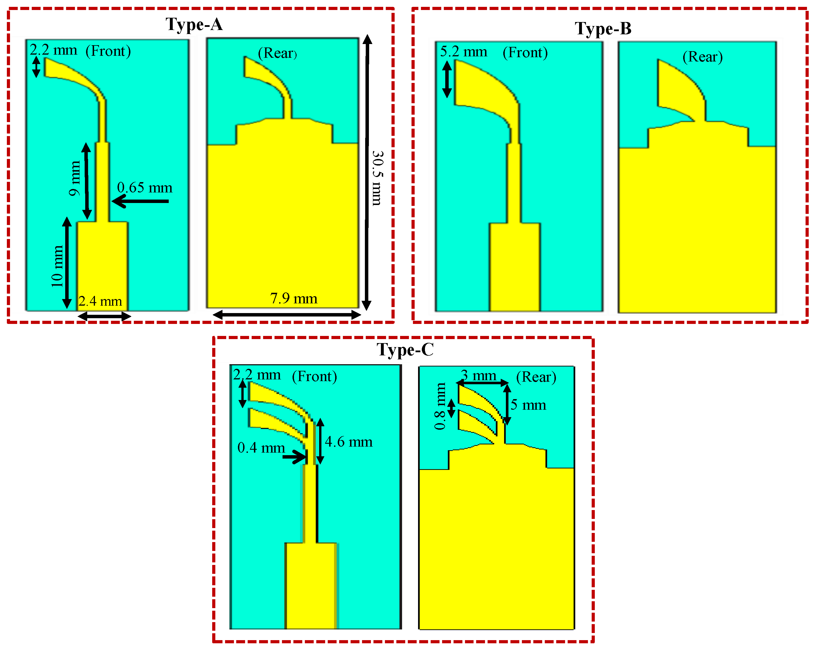
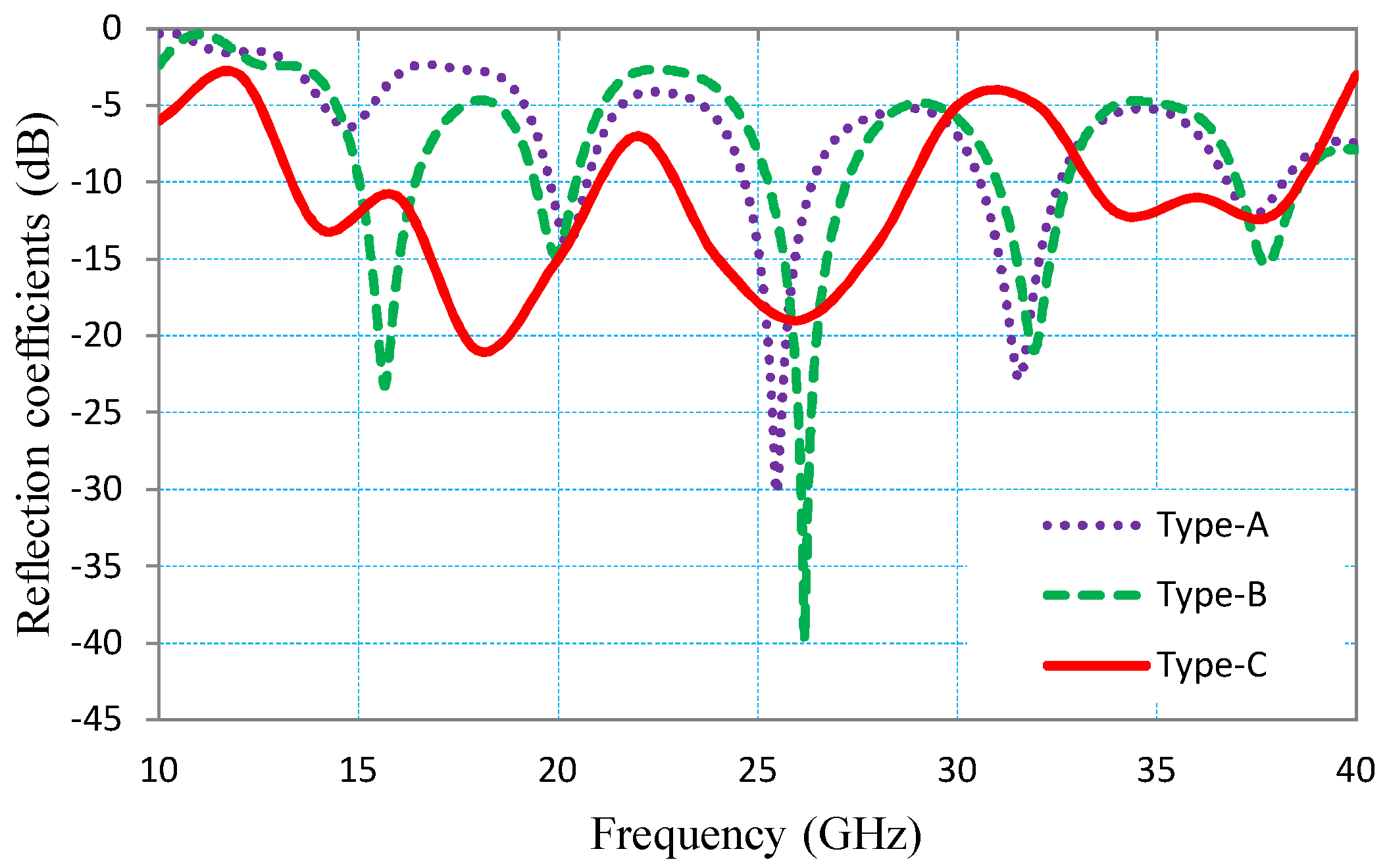
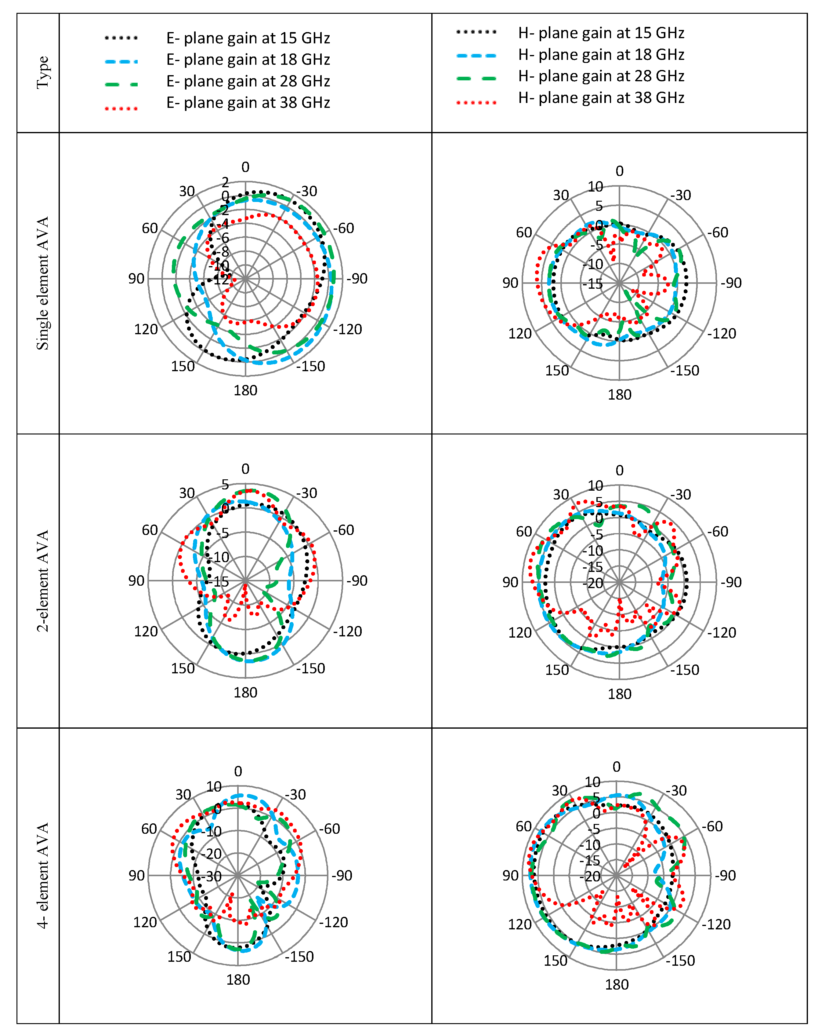
2.1. Optimization of the Single Element AVA Design

The single element AVA antenna is evolved in three stages, as shown in Figure 1. The type-A covers three frequency bands 19.81–20.71 GHz, 24.7–26.35 GHz, 36.79–38.17 GHz and has the limitation of not covering the lower frequency spectrum of the Ku-band. In type-B, the width of the radiating leaf is nearly doubled (to 5.2 mm) in order to cover the four frequency bands of 15.04–16.39 GHz, 19.42–20.44 GHz, 25.27–27.22 GHz, and 37.03–38.56 GHz. To enhance the bandwidth, the leaf structure of type-B is split into two thinner leaves (each 2.2 mm) which results in the proposed element geometry of type-C. The type-C antenna covers significant portion of the Ku (12–18 GHz), K (18–27 GHz), and Ka (27–40 GHz) frequency bands. The three bands covered by type-C are, 14.44–20.98 GHz, 24.34–29 GHz, and 33–40 GHz. These bands are designated by the IEEE and ITU for radar applications, however, the 28 GHz and 38 GHz are recently proposed for 5G mobile communications. Figure 2 compares the reflection coefficients (S 11 ) of the three types of antennas.

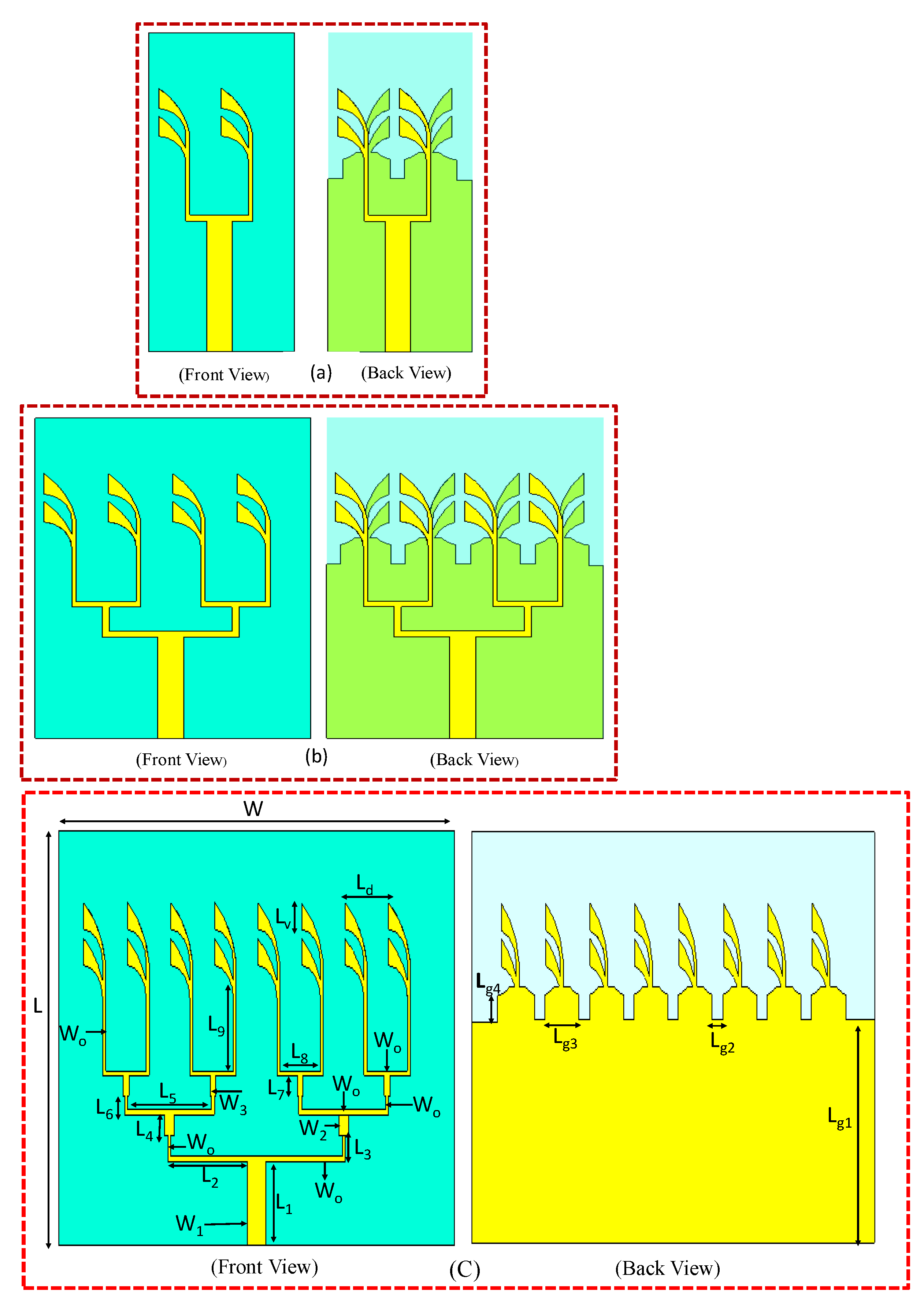
2.2. Optimization of the Multi-Element AVA Design

To meet the high-gain requirements of the 5G antennas operating in the mm wave frequency bands, the single element AVA (type-C in Figure 1) is converted into a two, four and eight element AVA array, as shown in Figure 3. The inter-element spacing between the individual antenna elements is set to 6 mm in order to obtain a broadside radiation pattern. The individual elements of the array antennas are excited by carefully designing a power-dividing network. The simulated S11, gain vs. frequency plots and the radiation patterns of the single and multi-element antennas are compared and illustrated in Figure 4, Figure 5, and Figure 6, respectively. The simulations are performed in CST MWS vs. 2018. The dimensions of the proposed 8-element array antenna are outlined in Table 1. The S 11 of the antennas (Figure 4) shows that minimal variations in the deriving-point impedance bandwidth (S 11 < −10 dB) of the single and multi-element antennas is observed. However it is worth-mentioning that as the number of radiating elements is increased from one to eight, the absolute gain of the antenna is significantly increased, for example, 3.6 to 12 dBi at f = 28 GHz. The radiation patterns of the antennas in the two principal planes, that is, E-plane ( ϕ = 90 ) and H-plane ( ϕ = 0 ) are compared in Figure 6, which shows that the gain of the main lobe is increased as the number of elements in the antenna array is increased, however, due to the mutual coupling between the neighboring elements, the direction of the main-lobe is slightly shifted. The mutual coupling between elements can be calculated when all elements of eight element AVA are fed by separate ports instead of single port as shown in Figure 7. The mutual coupling between elements of eight elements AVA is shown in Figure 8. It can be observed that mutual coupling between neighboring elements seems greater at lower frequencies than higher frequencies. This is due to spacing requirement, as lower frequency required greater spacing compared to higher frequencies. Therefore, while designing multiband array antenna, the spacing should be adjusted in keeping lower frequencies in mind to avoid mutual coupling. The spacing distance is adjusted at 6 mm (less than λ o / 2 ) which is calculated at 24 GHz. The summary of the main lobe magnitude (MLM), main lobe direction (MLD), half power beamwidth (HPBW), and side lobe level (SLL) is presented in Table 2. It is evident that as the gain of the antenna is increased, the HPBW is reduced [36,37]. It is also evident that beam steering along the main lobe direction occurs in the multi-element antennas, relative to the single element reference antenna.
Based on the aforementioned analysis, the eight-element antenna offers higher gain in the designated frequency bands, as compared to the rest of the candidate antennas and is considered as the proposed antenna for the 5G and Ku-band radar applications. This antenna is fabricated and the simulated results are validated in the far-field measurement facility.

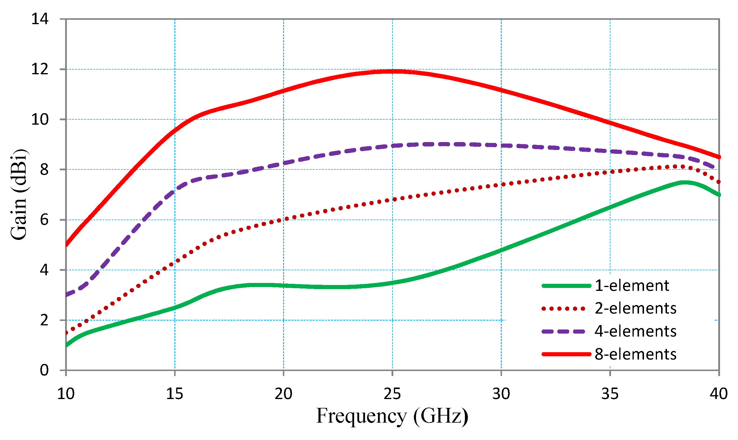
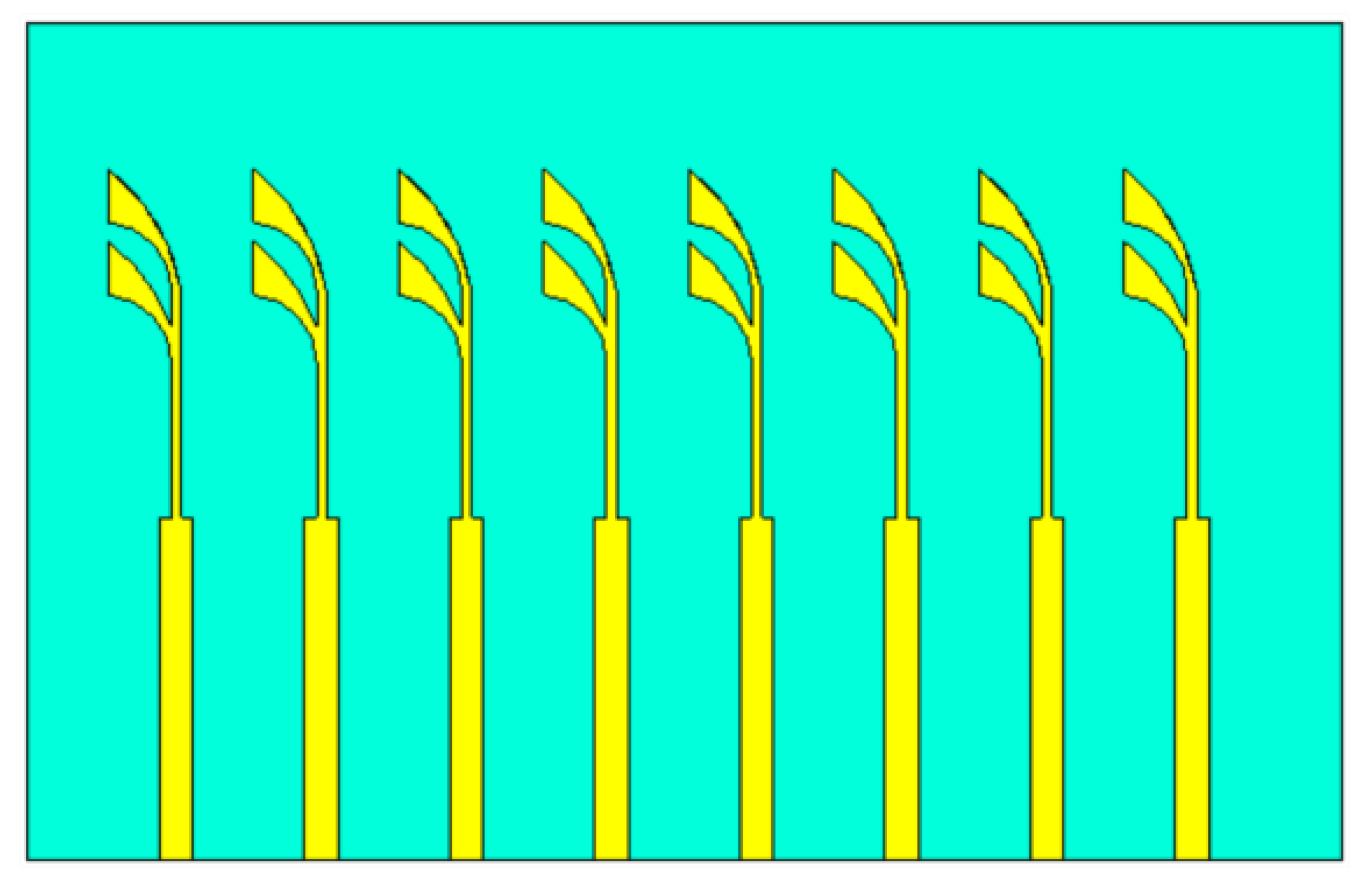
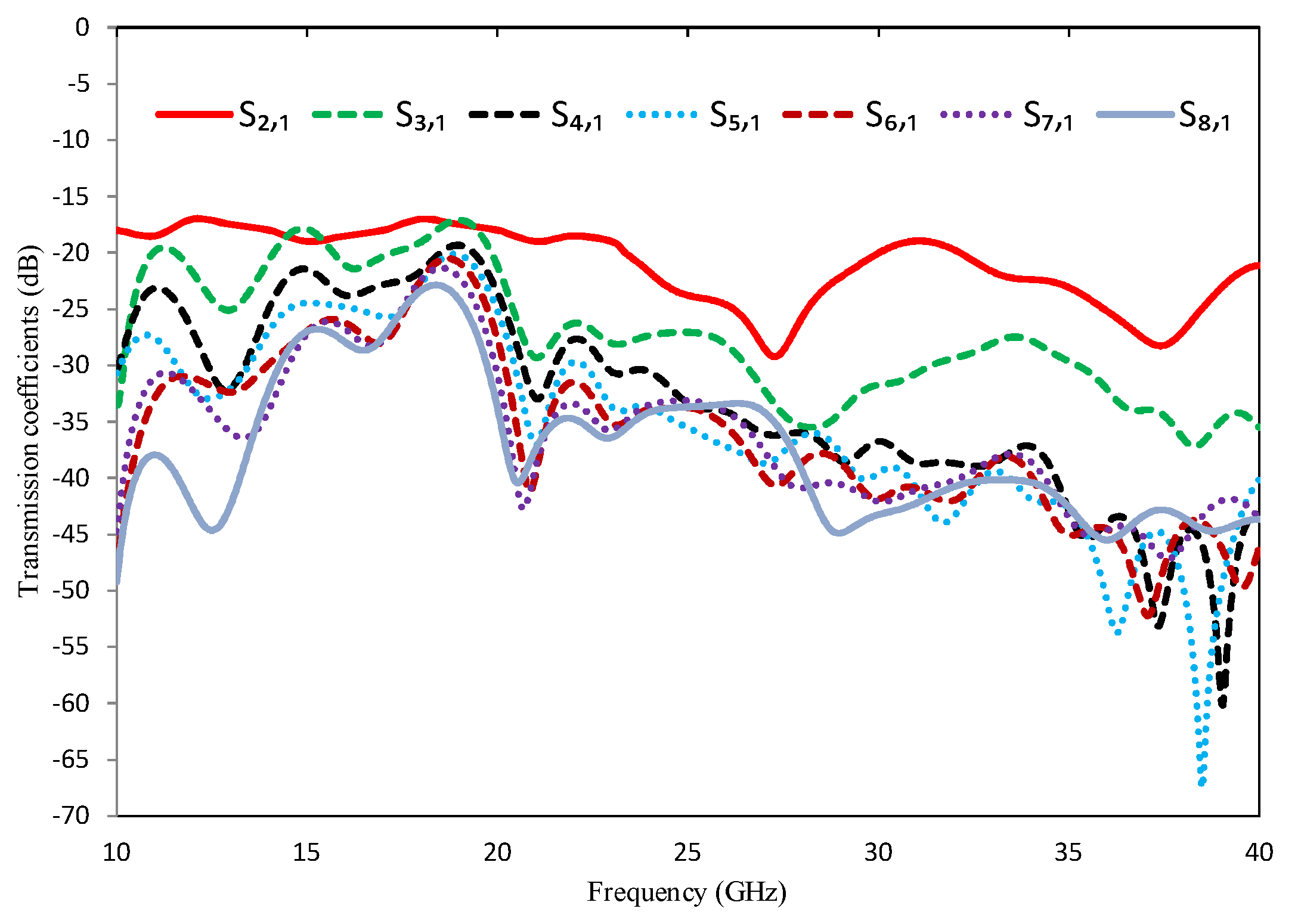
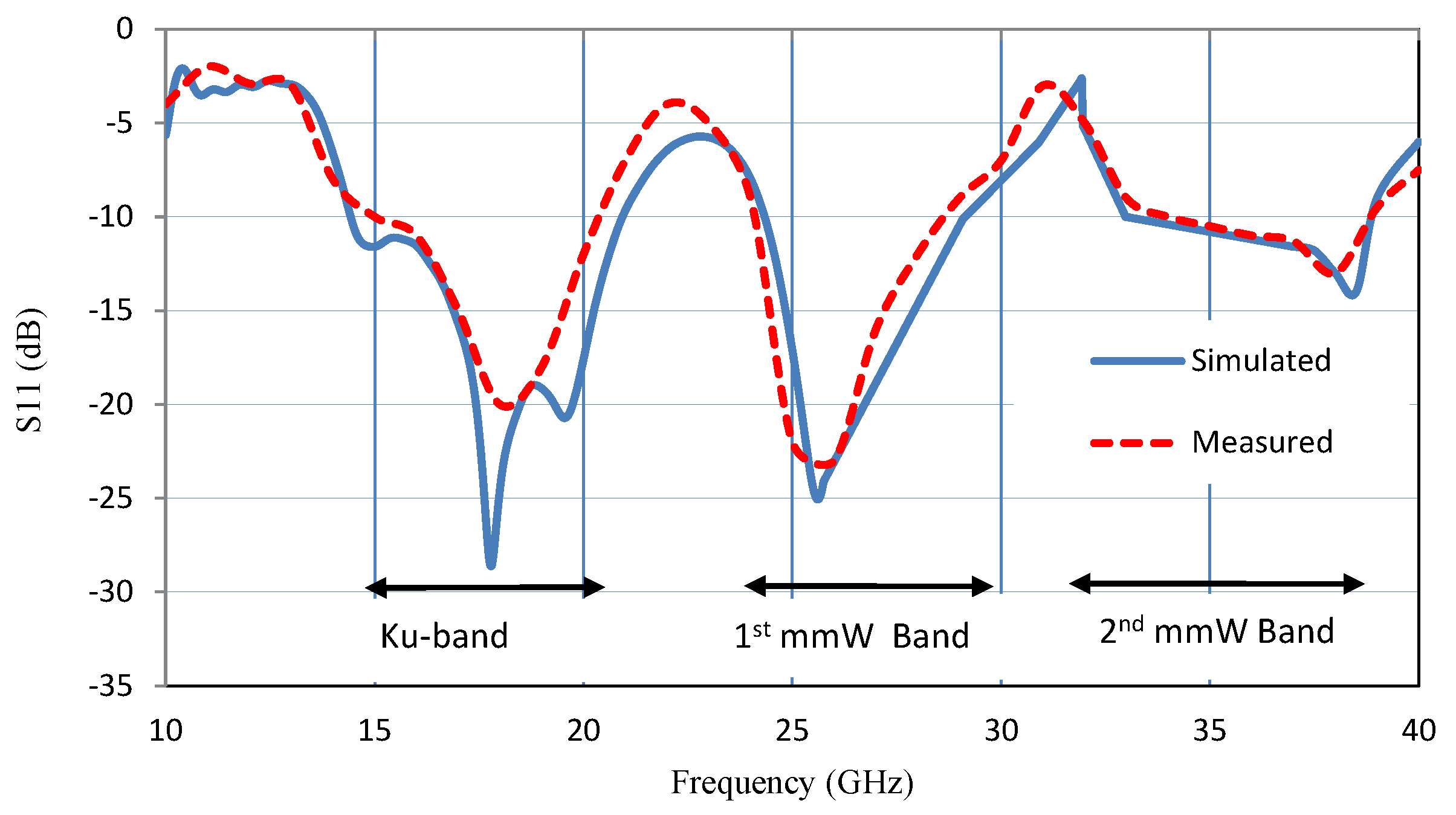
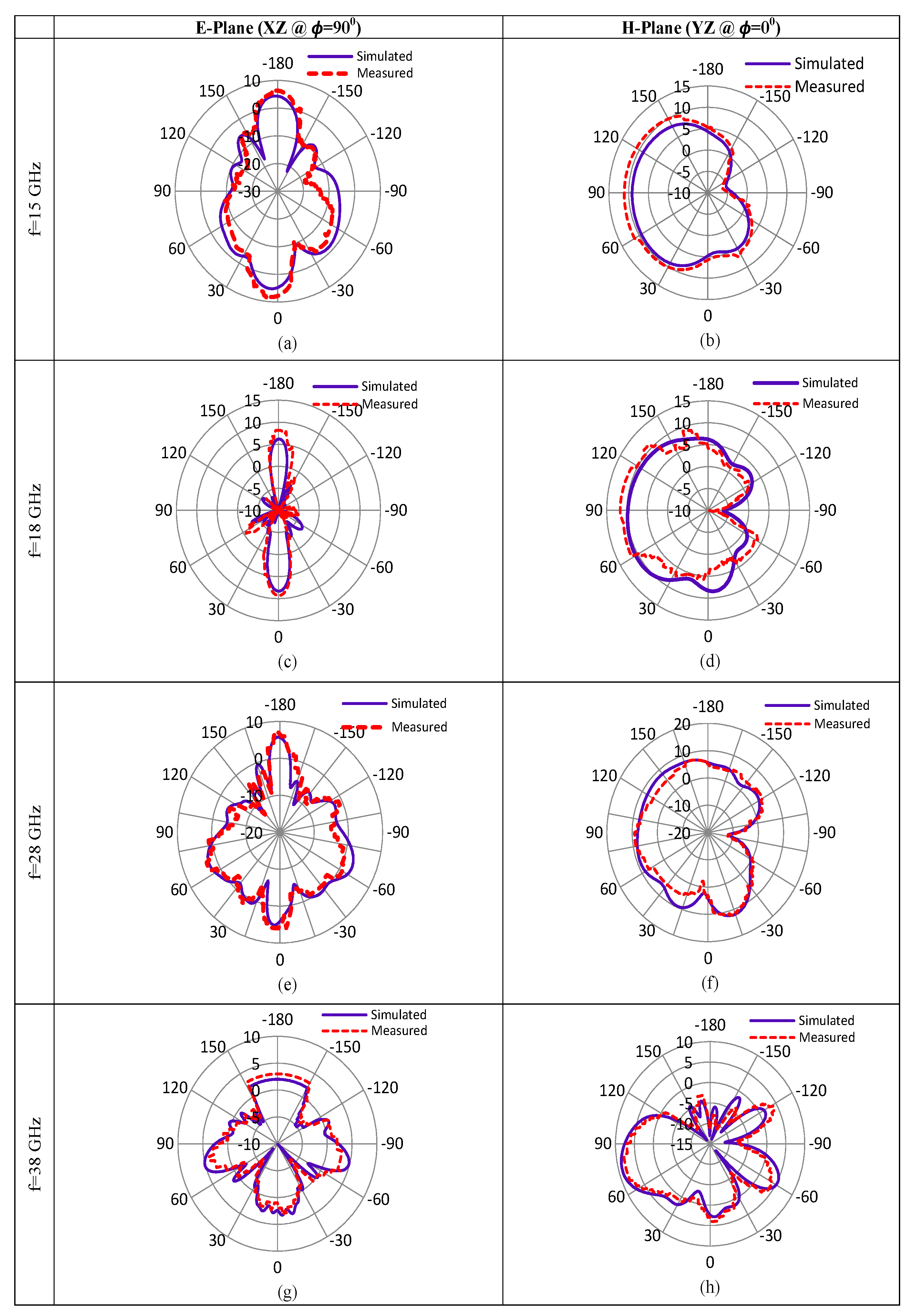
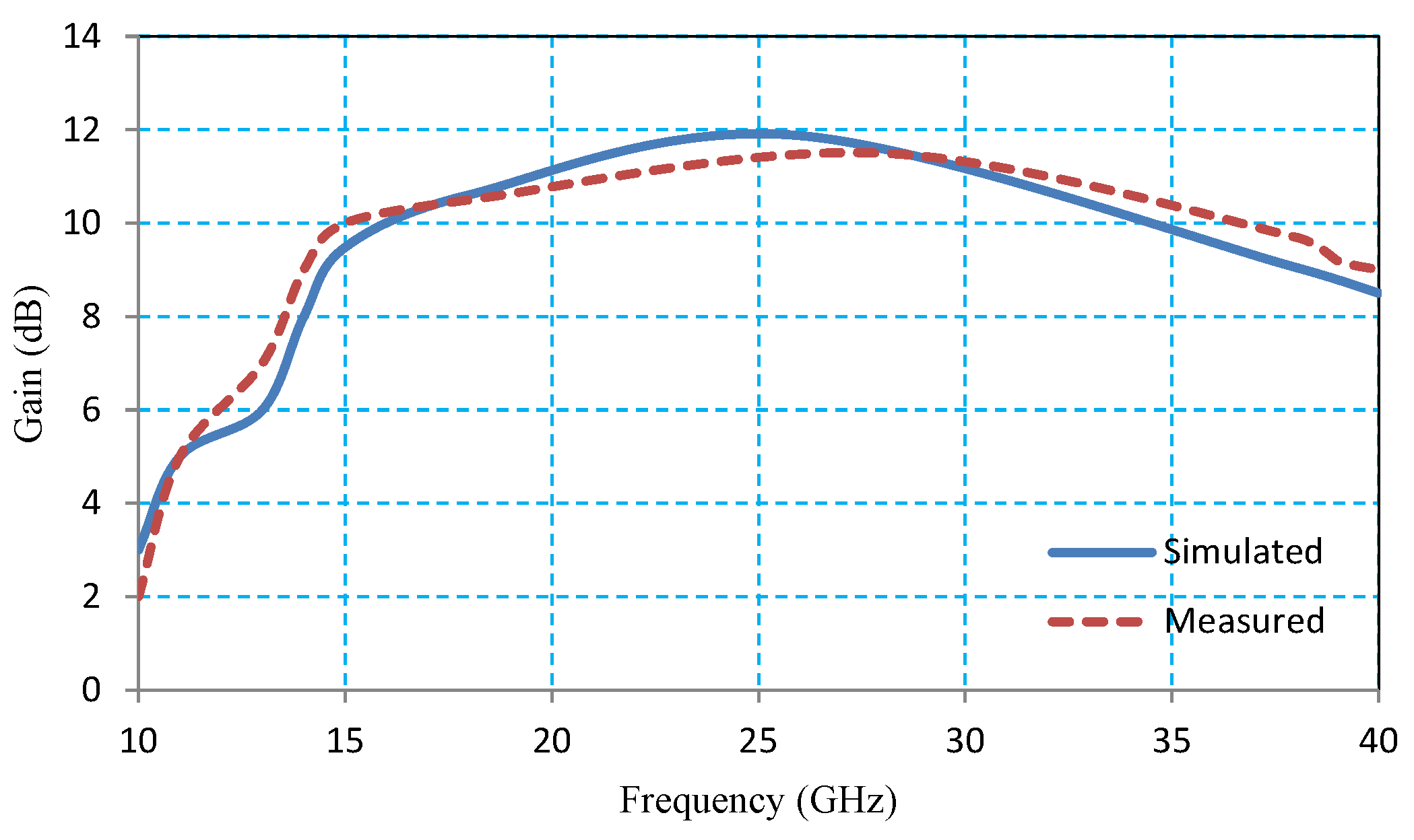
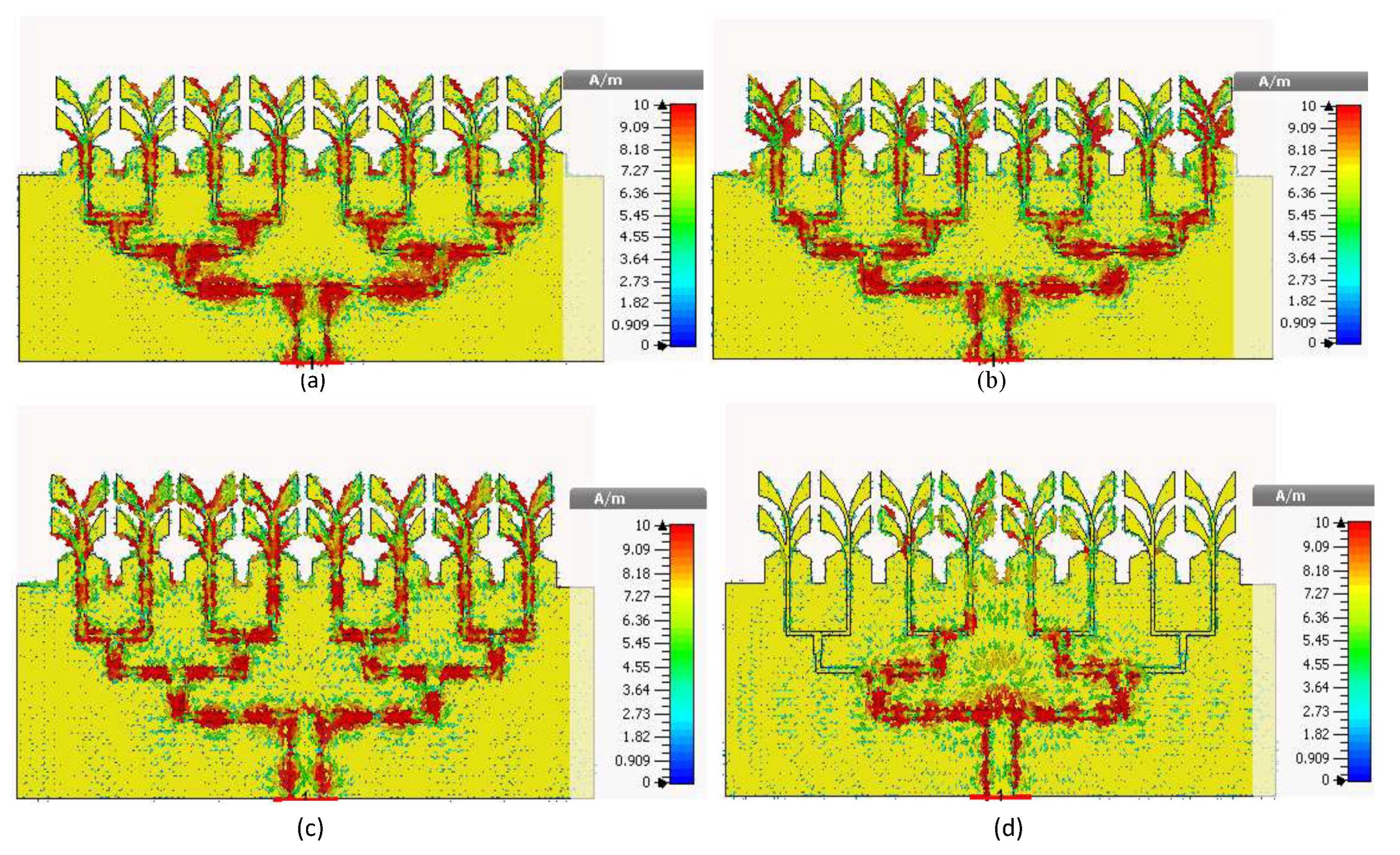
3. Analysis and Results Discussion of the Proposed 8-Elements AVA

The prototype of the proposed eight-element AVA array is fabricated as shown in Figure 9. The simulated reflection coefficient, radiation pattern, gain and efficiency of the antenna are validated in the antenna measurement facility.
The simulated and measured reflection coefficient (S11) are compared in Figure 10, and are found in close agreement. The S-parameter is below −10 dB in the following three resonant bands, that is,
  • Ku-Band (14.44–20.98 GHz)
  • 1st mmW band (24.34–29 GHz)
  • 2nd mmW band (33–40 GHz)
The simulated and measured radiation pattern of the antenna in the two principal planes, that is, E-plane (XZ @ ϕ = 90 ) and H-plane (YZ @ ϕ = 0 ) are compared in Figure 11 at 15 GHz, 18 GHz, 28 GHz, and 38 GHz. The measured and simulated radiation patterns are found in close agreement. It is evident from the results that the main beam of the radiation pattern is oriented along θ = 0 and 180 . Also strong radiations are observed at other angles in this plane. In the H-plane, the main beam is aligned nearly at 90 . For f = 15, 18, and 28 GHz, radiation pattern is somewhat Omni-directional in the third and fourth quadrants of the H-plane, however at f = 38 GHz strong radiation is observed in the third quadrant covering the angular range of θ = −30 to 100 . A major lobe with a sufficient gain (>5 dBi) occurs at θ = −60 in this plane for f = 38 GHz.
The simulated and measured gain plots as function of frequency are shown in Figure 12. Measured gain values of the proposed design at 15 GHz, 18 GHz, 28 GHz, and 38 GHz are 10 dBi, 10.5 dBi, 11.5 dBi, and 10 dBi, respectively. The proposed antenna presents decent gain (>10 dBi) in the targeted frequency bands and hence due to this high-gain capability it can be considered as a suitable candidate for 5G and radar applications.
To understand the insight operating mechanism of the proposed antenna at f = 15, 18, 28 and 38 GHz, the surface currents of the antenna are analyzed in Figure 13. It can be seen that the surface currents at 15 GHz and 18 GHz are concentrated at the center of lower part of the split leaf and spread along the edges. In contrast, the surface currents at 28 GHz are concentrated at the center of upper part of the split leaf and spread along the edges. While surface current are resides on the edges, as the frequency increased to 38 GHz. This concludes that lower part of the leaf is effective and generate radiation at 15 GHz and 18 GHz while upper part is the main contributor for radiation at 28 GHz and 38 GHz.
The simulated and measured efficiencies are shown in Figure 14. Proposed 8-element AVA array radiates efficiently (>86%) in the stated frequency bands, due to the properly matched design on a less lossy substrate.

4. Comparison with Existing Vivaldi Antennas

The proposed design is compared to other Vivaldi design in terms of size, as a function of wavelength, calculated at 18 GHz, operating frequency bands, Bandwidths, efficiencies, number of elements, and measured gain. It can be noticed that the size of the proposed antenna is normal compared to other Vivaldi antennas. The proposed antenna covers portions of Ku, K and Ka bands. It also covers the important segment of the mmW spectrum, allocated for 5G communication at 28 and 38 GHz. The proposed eight elements AVA is most efficient and has higher gain compared to others. The comparison with relevant antennas is shown in Table 3.

5. Conclusions

In this work, single element AVA antenna type-A, type-B, and type-C were designed. The former two designs type-A and type-B were evolved to later type-C for the advantage of additional coverage range of lower frequency spectrum of the Ku-band. The single element type-C AVA antenna covered three frequency bands that is, 14.44–20.98 GHz, 24.34–29 GHz, and 33–40 GHz. The Ku-band from 12–18 GHz is designed by the IEEE and ITU for radar and satellite communications, while 28 GHz and 38 GHz are allocated to 5G mobiles communications. Although, single element type-C AVA has good characteristics like stable radiation patterns, wide bandwidth, light weight, and easy to fabricate but still, it is not suitable for the 5G applications due to having less gain values 2.5 dBi, 3.4 dBi, 3.6 dBi, and 7.4 dBi at the targeted frequencies of 15 GHz, 18 GHz, 28 GHz, and 38 GHz, respectively. To meet the high gain requirements of the 5G antennas operating in the mmW frequency bands, the single element type-C AVA was extended into two, four, and eight element AVA arrays. The proposed eight elements AVA array showed high measured gain values of 10 dBi, 10.5 dBi, 11.5 dBi, and 10 dBi at 15 GHz, 18 GHz, 28 GHz, and 38 GHz, respectively. A prototype of the proposed antenna design was fabricated and experiments were conducted. The simulated and measured results were found closely matched. The proposed eight elements antenna is showing higher gains, stable radiation patterns, and wide bandwidths at all operating frequencies. Owing to the aforesaid characteristics, the proposed antenna could be considered a candidate for 5G mmWave communications and Ku-band applications.

Author Contributions

Conceptualization, R.U. (Raza Ullah) and S.U.; methodology, R.U. (Raza Ullah), D.-y.C. and R.U. (Rizwan Ullah); Software, R.U. (Raza Ullah), D.-y.C. and F.F.; Validation, S.U., D.-y.C., A.A., B.K.; Funding acquisition, D.-y.C. and A.A.; Investigation, S.U., D.-y.C., F.F., and B.K.; Resources, D.-y.C. and A.A.;Writing-review & editing, D.-y.C. and A.A.; Supervision, S.U. All authors have read and agreed to the published version of the manuscript.

Funding

The BrainKorea21Four Program supported this research through the National Research Foundation of Korea (NRF) funded by the Ministry of Education (4299990114316). Additionally, this research was also partially supported by the Basic Science Research Program through the National Research Foundation of Korea (NRF) funded by the Ministry of Education (2019R1F1A1058128).

Data Availability Statement

No new data were created or analyzed in this study. Data sharing is not applicable to this article.

Acknowledgments

The publication of this article was funded by the BrainKorea21Four Program supported this research through the National Research Foundation of Korea (NRF) funded by the Ministry of Education (4299990114316). Additionally, this research was also partially supported by the Basic Science Research Program through the National Research Foundation of Korea (NRF) funded by the Ministry of Education (2019R1F1A1058128).

Conflicts of Interest

The authors declare that there is no conflict of interest regarding this publication.

References

  1. Buttazzoni, G.; Babich, F.; Vatta, F.; Comisso, M. Geometrical Synthesis of Sparse Antenna Arrays Using Compressive Sensing for 5G IoT Applications. Sensors 2020, 20, 350. [Google Scholar] [CrossRef] [PubMed] [Green Version]
  2. Sa’don, S.N.H.; Jamaluddin, M.H.; Kamarudin, M.R.; Ahmad, F.; Yamada, Y.; Kamardin, K.; Idris, I.H. Analysis of Graphene Antenna Properties for 5G Applications. Sensors 2019, 19, 4835. [Google Scholar] [CrossRef] [Green Version]
  3. Ramos, A.; Varum, T.; Matos, J.N. Compact Multilayer Yagi-Uda Based Antenna for IoT/5G Sensors. Sensors 2018, 18, 2914. [Google Scholar] [CrossRef] [PubMed] [Green Version]
  4. Naqvi, A.H.; Lim, S. Review of Recent Phased Arrays for Millimeter-Wave Wireless Communication. Sensors 2018, 18, 3194. [Google Scholar] [CrossRef] [PubMed] [Green Version]
  5. Iffat Naqvi, S.; Hussain, N.; Iqbal, A.; Rahman, M.; Forsat, M.; Mirjavadi, S.S.; Amin, Y. Integrated LTE and Millimeter-Wave 5G MIMO Antenna System for 4G/5G Wireless Terminals. Sensors 2020, 20, 3926. [Google Scholar] [CrossRef] [PubMed]
  6. Song, C.; Pan, L.; Jiao, Y.; Jia, J. A High-Performance Transmitarray Antenna with Thin Metasurface for 5G Communication Based on PSO (Particle Swarm Optimization). Sensors 2020, 20, 4460. [Google Scholar] [CrossRef]
  7. Ali, I.; Jamaluddin, M.H.; Gaya, A.; Rahim, H.A. A Dielectric Resonator Antenna with Enhanced Gain and Bandwidth for 5G Applications. Sensors 2020, 20, 675. [Google Scholar] [CrossRef] [Green Version]
  8. Zhang, J.; Zhang, S.; Lin, X.; Fan, Y.; Pedersen, G.F. 3D Radiation Pattern Reconfigurable Phased Array for Transmission Angle Sensing in 5G Mobile Communication. Sensors 2018, 18, 4204. [Google Scholar] [CrossRef] [Green Version]
  9. Ojaroudi Parchin, N.; Alibakhshikenari, M.; Jahanbakhsh Basherlou, H.; Abd-Alhameed, R.A.; Rodriguez, J.; Limiti, E. MM-Wave Phased Array Quasi-Yagi Antenna for the Upcoming 5G Cellular Communications. Appl. Sci. 2019, 9, 978. [Google Scholar] [CrossRef] [Green Version]
  10. Ojaroudi Parchin, N.; Jahanbakhsh Basherlou, H.; Al-Yasir, Y.I.A.; Ullah, A.; Abd-Alhameed, R.A.; Noras, J.M. Multi-Band MIMO Antenna Design with User-Impact Investigation for 4G and 5G Mobile Terminals. Sensors 2019, 19, 456. [Google Scholar] [CrossRef] [Green Version]
  11. Ojaroudi Parchin, N.; Jahanbakhsh Basherlou, H.; Al-Yasir, Y.I.A.; Abdulkhaleq, A.M.; Patwary, M.; Abd-Alhameed, R.A. A New CPW-Fed Diversity Antenna for MIMO 5G Smartphones. Electronics 2020, 9, 261. [Google Scholar] [CrossRef] [Green Version]
  12. Ojaroudi Parchin, N.; Jahanbakhsh Basherlou, H.; Alibakhshikenari, M.; Ojaroudi Parchin, Y.; Al-Yasir, Y.I.A.; Abd-Alhameed, R.A.; Limiti, E. Mobile-Phone Antenna Array with Diamond-Ring Slot Elements for 5G Massive MIMO Systems. Electronics 2019, 8, 521. [Google Scholar] [CrossRef] [Green Version]
  13. Khalid, M.; Iffat Naqvi, S.; Hussain, N.; Rahman, M.; Fawad; Mirjavadi, S.S.; Khan, M.J.; Amin, Y. 4-Port MIMO Antenna with Defected Ground Structure for 5G Millimeter Wave Applications. Electronics 2020, 9, 71. [Google Scholar] [CrossRef] [Green Version]
  14. Choi, J.; Park, J.; Youn, Y.; Hwang, W.; Seong, H.; Whang, Y.N.; Hong, W. Frequency-Adjustable Planar Folded Slot Antenna Using Fully Integrated Multithrow Function for 5G Mobile Devices at Millimeter-Wave Spectrum. IEEE Trans. Microw. Theory Tech. 2020, 68, 1872–1881. [Google Scholar] [CrossRef]
  15. Shafi, M.; Molisch, A.F.; Smith, P.J.; Haustein, T.; Zhu, P.; de Silva, P.; Tufvesson, F.; Benjebbour, A.; Wunder, G. 5G: A Tutorial Overview of Standards, Trials, Challenges, Deployment and Practice. IEEE J. Sel. Areas Commun. 2017, 35, 1201–1221. [Google Scholar] [CrossRef]
  16. Rappaport, T.S.; MacCartney, G.R.; Samimi, M.K.; Sun, S. Wideband millimeter-wave propagation measurements and channel models for future wireless communication system design. IEEE Trans. Commun. 2015, 63, 3029–3056. [Google Scholar] [CrossRef]
  17. Mak, K.M.; Lai, L.W.; Luk, K.M. A 5G Wideband Patch Antenna with Antisymmetric L-shaped Probe Feeds. IEEE Trans. Antennas Propag. 2018, 66, 957–961. [Google Scholar] [CrossRef]
  18. Ullah, R.; Ullah, S.; Umar, S.M.; Ullah, R.; Kamal, B. Design and Modeling of a 28/38/60/70/80 GHz Antenna for Fifth Generation (5G) Mobile and Millimeter Wave (mmW) Applications. In Proceedings of the 2019 International Conference on Electrical, Communication, and Computer Engineering (ICECCE), Swat, Pakistan, 24–25 July 2019; pp. 1–7. [Google Scholar]
  19. Syrytsin, I.; Zhang, S.; Pedersen, G.F. Compact Quad-Mode Planar Phased Array with Wideband for 5G Mobile Terminals. IEEE Antennas Wirel. Propag. Lett. 2018, 66, 4648–4657. [Google Scholar] [CrossRef] [Green Version]
  20. Wei, L.; Hu, R.Q.; Qian, Y.; Wu, G. Key elements to enable millimeter wave communications for 5G wireless systems. IEEE Wirel. Commun. 2014, 21, 136–143. [Google Scholar]
  21. Nassar, I.T.; Weller, T.M. A novel method for improving antipodal Vivaldi antenna performance. IEEE Trans. Antennas Propag. 2015, 63, 3321–3324. [Google Scholar] [CrossRef]
  22. Xu, H.-X.; Wang, G.-M.; Tao, Z.; Cui, T.J. High-directivity emissions with flexible beam numbers and beam directions using gradientrefractive-index fractal metamaterial. Sci. Rep. 2014, 4, 5744. [Google Scholar] [CrossRef] [PubMed] [Green Version]
  23. Moosazadeh, M.; Kharkovsky, S. A compact high-gain and front-toback ratio elliptically tapered antipodal Vivaldi antenna with trapezoidshaped dielectric lens. IEEE Antennas Wirel. Propag. Lett. 2016, 15, 552–555. [Google Scholar] [CrossRef]
  24. Zhang, H.; Sun, H.; Yang, T.; Mahe, Y.; Razban, T. Design of A Wideband and Dual-Polarized CPW-Fed Monopole Antenna for Future 5G Communications. In Proceedings of the 2016 IEEE 84th Vehicular Technology Conference (VTC-Fall), Montreal, QC, Canada, 18–21 September 2016; pp. 1–5. [Google Scholar]
  25. Ying, Z.; Zhao, K.; Bolin, T.; He, S.; Scannavini, A.; Foged, L.J.; Nicolas, G. Multiplexing Efficiency of High Order MIMO in Mobile Terminal for 5G communication at 15GHz. In Proceedings of the 2016 International Symposium on Antennas and Propagation (ISAP), Okinawa, Japan, 24–28 October 2016; pp. 594–595. [Google Scholar]
  26. Xu, B.; Zhao, K.; Thors, B.; Colombi, D.; Lundberg, O.; Ying, Z.; He, S. Power Density Measurements at 15 GHz for RF EMF Compliance Assessments of 5G User Equipment. IEEE Trans. Antennas Propag. 2017, 65, 6584–6595. [Google Scholar] [CrossRef]
  27. Zhao, K.; Ying, Z.; He, S. Human Exposure to mmWave Phased Array Antennas in Mobile Terminal for 5G Mobile System. In Proceedings of the 2015 IEEE 81st Vehicular Technology Conference (VTC Spring), Glasgow, UK, 11–14 May 2015; pp. 1–2. [Google Scholar]
  28. Asbeck, P.M. Will Doherty Continue to Rule for 5G? In Proceedings of the 2016 IEEE MTT-S International Microwave Symposium (IMS), San Francisco, CA, USA, 22–27 May 2016; pp. 1–4. [Google Scholar]
  29. Tsutsumi, K.; Yamamoto, W.; Maruyama, T.; Fujiwara, T.; Somada, I.; Hagiwara, T.; Taniguchi, E. A 15GHz 4-Channel Transmit/Receive RF Core-Chip for High SHF Wide-band Massive MIMO in 5G. In Proceedings of the 2017 IEEE 17th Topical Meeting on Silicon Monolithic Integrated Circuits in RF systems (SiRF), Phoenix, AZ, USA, 15–18 January 2017; pp. 115–117. [Google Scholar]
  30. Scannavini, A.; Foged, L.J.; Giacomini, A.; Duchesne, L.; Gross, N.; Herbiniere, F. Efficient testing of antennas for 5G mm-wave applications. In Proceedings of the 12th European Conference on Antennas and Propagation (EuCAP 2018), London, UK, 9–13 April 2018; pp. 1–4. [Google Scholar]
  31. Noren, P.; Foged, L.J.; Scialacqua, L.; Scannavini, A. Measurement and Diagnostics of Millimeter Waves 5G Enabled Devices. In Proceedings of the 2018 IEEE Conference on Antenna Measurements & Applications (CAMA), Vasteras, Sweden, 3–6 September 2018; pp. 1–4. [Google Scholar]
  32. Abdalrazik, A.; Abdelrahman, A.B.; Allam, A.; Abo-Zahhad, M. A Wideband Dielectric Resonator Antenna with Truncated Ground for 5G Applications. In Proceedings of the 2018 48th European Microwave Conference (EuMC), Madrid, Spain, 23–27 September 2018; pp. 1085–1086. [Google Scholar]
  33. Yang, Y.; Sun, B.; Guo, J. A Single-Layer Wideband Circularly Polarized Antenna for Millimeter-Wave Applications. IEEE Trans. Antennas Propag. 2020, 68, 4925–4929. [Google Scholar] [CrossRef]
  34. Liu, P.; Zhu, X.; Zhang, Y.; Wang, X.; Yang, C.; Jiang, Z.H. Patch Antenna Loaded With Paired Shorting Pins and H-Shaped Slot for 28/38 GHz Dual-Band MIMO Applications. IEEE Access 2020, 8, 23705–23712. [Google Scholar] [CrossRef]
  35. Khan, Z.U.; Loh, T.H.; Belenguer, A.; Alomainy, A. Empty Substrate-Integrated Waveguide-Fed Patch Antenna Array for 5G Millimeter-Wave Communication Systems. IEEE Antennas Wirel. Propag. Lett. 2020, 19, 776–780. [Google Scholar] [CrossRef]
  36. Gudarzi, A.; Mahzoon, M.; Bazrkar, A.; Mohajeri, F. Gain enhancement and miniaturization of microstrip antennas using MTM superstrates. In Proceedings of the 2012 International Conference on Computer and Communication Engineering (ICCCE), Kuala Lumpur, Malaysia, 3–5 July 2012; pp. 859–863. [Google Scholar]
  37. Balanis, C.A. Antenna Theory: Analysis and Design, 3rd ed.; Wiley-Interscience: New York, NY, USA, 2005. [Google Scholar]
  38. Dixit, A.S.; Kumar, S. The enhanced gain and cost-effective antipodal Vivaldi antenna for 5G communication applications. Microw. Opt. Technol. Lett. 2020, 62, 2365–2374. [Google Scholar] [CrossRef]
  39. Masoodi, I.S.; Ishteyaq, I.; Muzaffar, K.; Magray, M.I. Low Cost Substrate Based Compact Antennas for 4G/5G Side-Edge Panel Smartphone Applications. Prog. Electromagn. Res. Lett. 2020, 91, 145–152. [Google Scholar] [CrossRef]
  40. Gorai, A.; Karmakar, A.; Pal, M.; Ghatak, R. A super wideband Chebyshev tapered antipodal Vivaldi antenna. AEU Int. Electron. Commun. 2015, 69, 1328–1333. [Google Scholar] [CrossRef]
  41. Goel, T.; Patnaik, A. Novel Broadband Antennas for Future Mobile Communications. IEEE Trans. Antennas Propag. 2018, 66, 2299–2308. [Google Scholar] [CrossRef]
  42. Yang, K.; Hoang, M.H.; Bao, X.; McEvoy, P.; Ammann, M.J. Dual-stub Ka-band Vivaldi antenna with integrated bandpass filter. IET Microw. Antennas Propag. 2018, 12, 668–671. [Google Scholar] [CrossRef] [Green Version]
  43. Bai, J.; Shi, S.; Prather, D.W. Modified compact antipodal Vivaldi antenna for 4-50-GHz UWB application. IEEE Trans. Microw. Theory Tech. 2011, 59, 1051–1057. [Google Scholar] [CrossRef]
  44. Lee, W.; Hwang, I.; Jang, B. End-Fire Vivaldi Antenna Array With Wide Fan-Beam for 5G Mobile Handsets. IEEE Access 2020, 8, 118299–118304. [Google Scholar] [CrossRef]
  45. Si, L.-M.; Tang, H.-B.; Shui, X.; Lu, H.-D.; Liu, Y.; Ge, Y.-F.; Lv, X. Design of a 6–18 GHz UWB conformal antipodal Vivaldi antenna array. In Proceedings of the 2013 IEEE International Conference on Microwave Technology & Computational Electromagnetics, Qingdao, China, 25–28 August 2013; pp. 153–156. [Google Scholar] [CrossRef]
  46. Dixit, A.S.; Kumar, S. A Miniaturized Antipodal Vivaldi Antenna for 5G Communication Applications. In Proceedings of the 2020 7th International Conference on Signal Processing and Integrated Networks (SPIN), Noida, India, 27–28 February 2020; pp. 800–803. [Google Scholar]
Figure 1. Optimization of the single element antipodal Vivaldi antenna.
Electronics 10 00667 g001
Figure 2. Comparison of reflection coefficient (S 11 ) by optimizing the structure of the single element AVA.
Electronics 10 00667 g002
Figure 3. Geometry of multi-element array antennas. (a) 2-element array. (b) 4-element array. (c) 8-element array.
Electronics 10 00667 g003
Figure 4. S 11 comparison of single and multi-element antennas.
Electronics 10 00667 g004
Figure 5. Gain comparison of the single and multi-element AVA antennas as function of frequency.
Electronics 10 00667 g005
Figure 6. Comparison of radiation pattern in the E- and H-planes.
Electronics 10 00667 g006
Figure 7. Eight element AVA with separate ports.
Electronics 10 00667 g007
Figure 8. Transmission coefficients of eight elements AVA fed by separate ports.
Electronics 10 00667 g008
Figure 9. Fabricated antenna. (a) Front view. (b) Back view.
Electronics 10 00667 g009
Figure 10. Comparison of simulated and measured S11 of the proposed antenna.
Electronics 10 00667 g010
Figure 11. Comparison of the simulated and measured radiation patterns of the proposed antenna.
Electronics 10 00667 g011
Figure 12. Comparison of simulated and measured gain of the proposed antenna.
Electronics 10 00667 g012
Figure 13. Surface current plots of the proposed antenna. (a) 15 GHz. (b) 18 GHz. (c) 28 GHz. (d) 38 GHz.
Electronics 10 00667 g013
Figure 14. Simulated and measured efficiencies verses frequency of 8-element AVA.
Electronics 10 00667 g014
Table 1. Dimensions of the 8-element AVA.
ParameterLL1L2L3L4L5L6
Value (mm)33.317122.21.6912.41.6
ParameterL 7 L 8 L 9 L v L d L g 1 L g 2
Value (mm)1.6536.46.4052.2618.7481.4
ParameterL g 3 L g 4 WW 1 W o W 2 W 3
Value (mm)52.25254.962.430.41.3710.811
Table 2. Main lobe magnitude (MLM), main lobe direction (MLD), half power beamwidth (HPBW), and side lobe level (SLL) of the proposed antennas AVAs.
(a) 1– Element(c) 4– Element
f (GHz)PlaneMLMMLDHPBWSLLf (GHz)PlaneMLMMLDHPBWSLL
(dB)(deg)(deg)(dB) (dB)(deg)(deg)(dB)
15E1.02–31137.3–1.1 E2.791048.2–11.1
H2.33–73153.7–2.115H7.1755138.4–4.7
18E1.02–139228.60 E5.81–636.9–2.1
H3.1194169.7–2.118H7.8967125.5–2.3
28E1.19–452660 E2.9218024.9–1.5
H3.2103120–228H7.863541.7–2.6
38E–1.53–99201.20 E3.77–3385.9–0.9
H6.547661.2–538H7.863541.7–2.6
(b) 2– Element(d) 8–Element
f (GHz)PlaneMLMMLDHPBWSLLf (GHz)PlaneMLMMLDHPBWSLL
(dB)(deg)(deg)(dB) (dB)(deg)(deg)(dB)
15E1–17109.10 E5.4422–7.1
H4.240156.9015H9.5646155.5–4.2
18E1.62–17472.60 E8.24018.2–1.8
H5.147 164.3018H10.658130–2.2
28E3.66–760.3–2.2 E5.75113–2.6
H6.8461112.9–2.528H11.9–1926.4–2.3
38E3.55–440.6–3 E5.117526.4–1.7
H8.137642.8–4.138H9.067442.7–3.8
Table 3. Comparison of proposed 5G AVA to other Vivaldi antennas.
Comparison of Single Element Designs
Ref No.YearSize ( λ × λ × λ )Operating FrequencyBWEfficienciesNumberMeasured
( λ Is Taken in mm)(GHz)(GHz)(%)of ElementsGain (dBi)
[38]20206.93 × 4.15 × 0.2724.8–34.529.72N.M017.27
[39]20200.56 × 0.82 × 0.04623–3916N.M017.2
[40]20150.7 × 0.7 × 0.0111–3534>77016.8
[41]20182.087 × 1.52 × 0.0910–4030N.M018.5
[42]20184.51 × 2.136 × 0.03327–310484.9018.51
[43]20113.3 × 3.43 × 0.0154–5046N.M013–12
1.83 × 0.47 × 0.0514.44–20.986.54 3.4
This 24.34–294.66>86013.6
Work 33–407 7.4
Comparison of Four Element Designs
Ref No.YearSize ( λ × λ × λ )Operating FrequencyBWEfficienciesNumberMeasured
( λ Is Taken in mm)(GHz)(GHz)(%)of ElementsGain (dBi)
[44]20205.60 × 12.61 × 0.07327.5–28.50180048.01
[45]20132.02 × 1.52 × 1.526–186N.M04N.M
2.69 × 2.24 × 0.02324.91–33.188.27
[46]2020 34.95–36.581.63N.M04N.M
38.34–39.381.04
1.8 × 2.1 × 0.0514.44–20.986.54 8.10
This 24.34–294.66>86048.32
Work 33–407 8.54
Proposed Eight Element Design
Ref No.YearSize ( λ × λ × λ )Operating FrequencyBWEfficienciesNumberMeasured
( λ Is Taken in mm)(GHz)(GHz)(%)of ElementsGain (dBi)
2 × 3.3 × 0.0514.44–20.986.54
This 24.34–294.66>8608>10
Work 33–407
Publisher’s Note: MDPI stays neutral with regard to jurisdictional claims in published maps and institutional affiliations.

