Abstract
The estimation of signal parameters via rotational invariance techniques (ESPRIT) is an algorithm that uses the shift-invariant properties of the array antenna to estimate the direction-of-arrival (DOA) of signals received in the array antenna. Since the ESPRIT algorithm requires high-complexity operations such as covariance matrix and eigenvalue decomposition, a hardware processor must be implemented such that the DOA is estimated in real time. Additionally, the ESPRIT processor should support a scalable number of antenna configuration for DOA estimation in various applications because the performance of ESPRIT depends on the number of antennas. Therefore, we propose an ESPRIT processor that supports two to eight scalable antenna configuration. In addition, since the proposed ESPRIT processor is based on multiple invariances (MI) algorithm, it can achieve a much better performance than the existing ESPRIT processor. The execution time is reduced by simplifying the Jacobi method, which has the most significant computational complexity for calculating eigenvalue decomposition (EVD) in ESPRIT. Moreover, the ESPRIT processor was designed using hardware description language (HDL), and an FPGA-based verification was performed. The proposed ESPRIT processor was implemented with 10,088 slice registers, 18,207 LUTs, and 80 DSPs, and the slice register, LUT, and DSP were reduced by up to 71.45%, 54.5%, and 68.38%, respectively, compared to the existing structure.
1. Introduction
Direction-of-arrival (DOA) estimation of a signal using an array antenna system is widely used in various applications such as radar and communication [1,2,3,4]. The multiple signal classification (MUSIC) and estimation of signal parameters via rotational invariance techniques (ESPRIT) algorithms are the most widely used DOA estimation algorithms [5,6]. The MUSIC calculates a spectrum for a spatial angle by using the principle that the steering vector of the received signal is orthogonal to the noise subspace. Then, the DOA of the signal is obtained by finding the peak value in the calculated spectrum [7]. The MUSIC algorithm has high computational complexity because it requires extensive peak searches across all spectra [8].
In contrast, the ESPRIT algorithm uses a structure with two shift-invariant subarrays of an array antenna for estimating the DOA [9]. Because the ESPRIT algorithm can obtain DOA without the need to find a peak in the spectrum, its computational complexity is lower than that of the MUSIC algorithm [10,11]. Consequently, ESPRIT satisfies the trade-off between performance and hardware complexity [12]. However, ESPRIT algorithms still require high-complexity operations such as covariance matrix calculation and eigenvalue decomposition (EVD). Thus, hardware implementation is necessary to estimate the DOA in real-time.
The use of ESPRIT processors in various applications require high-precision DOA estimation performance as well as real-time processing. The performance of ESPRIT depends on the number of antennas, which is further dependent on the application [13,14]. For applications that require high DOA precision, a large number of antennas should be configured, whereas a small number of antennas need to be configured for applications that require low cost implementation. Therefore, it is essential that the ESPRIT processor supports a variable number of antenna configurations and caters to various applications. Many studies have been conducted to exploit multiple invariances of antenna arrays [15,16]. Xu proposed a multiple invariances (MI)-ESPRIT algorithm that improves performance using low computation and MI of the ESPRIT algorithm [17]. The MI-ESPRIT algorithm can perform subarray unit calculations, which helps cater to applications that require a variable number of antennas.
Various studies have been conducted with regard to the real-time implementation of the ESPRIT. Alhamed performed EVD operations using QR decomposition methods for implementing an ESPRIT processor with low complexity on an FPGA for the purpose of real-time processing [18]. In addition, Hussain designed the ESPRIT processor using LU decomposition to lower the hardware complexity rather than the frequently used QR decomposition method [19]. However, Hussain’s ESPRIT processor only supports a configuration with four antennas. Another way to implement EVD with low complexity is the cyclic Jacobi method [20]. This method simply rotates the plane in a repetitive manner and calculates the eigenvalue and eigenvector which yields lower complexity as compared to QR and LU decomposition. However, both the number of iterations and execution time increases rapidly with the number of antennas [21].
In this paper, we propose an ESPRIT processor that supports two to eight scalable antennas. The proposed ESPRIT processor achieves a much better performance than the existing ESPRIT processor because it exploits multiple invariances based on the MI-ESPRIT structure. The hardware complexity was reduced by simplifying the least-squares method and the execution time was also dramatically reduced by decreasing the number of iterations of the cyclic Jacobi method. The remainder of this paper is organized as follows. In Section 2, we review the ESPRIT algorithm for estimating DOA. The hardware architecture of the proposed ESPRIT processor is described in Section 3. In Section 4, we present the implementation results of the proposed ESPRIT processor. Finally, Section 5 concludes the paper.
2. ESPRIT Algorithm for Estimating DOA
2.1. Signal Model
The ESPRIT algorithm estimates the DOA using the data received from a uniform linear array (ULA) antenna. As shown in Figure 1, considering that the reflected signal from targets is incident at different DOAs () of the ULA antenna composed of sensors, the received signal can be modeled as follows:
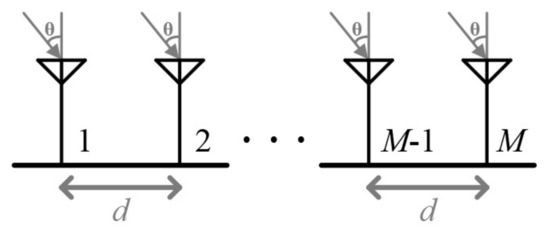
Figure 1.
Uniform linear array antenna.
In Equation (1), is a × 1 output vector of the antenna array and is the output of the -th element at . is a × 1 data vector of reflected signal targets and is the -th signal at . is a × 1 data vector of noises which are additive white Gaussian noises (AWGN) and the noises of each array element are not relevant. is the noise of the -th element at . is a matrix of × , and it is composed of an array of steering vectors with a constant phase difference according to the incident angles of the received signals, as shown in Equations (2) and (3).
where is the steering vector by the -th source, is the wavelength of the signal, is the distance between the elements of the ULA, and is the DOA of the -th source. To apply the ESPRIT algorithm, the covariance matrix of the received signal in Equation (1) can be expressed as Equation (4) below:
where denotes statistical expectation, the subscript denotes conjugate transpose, is the variance of AWGN, and is an identity matrix of size × . Because the actual expectation value cannot be obtained, the covariance matrix operation is performed by calculating the average value as shown in Equation (5) from snapshots.
After the covariance matrix operation is obtained from Equation (5), the eigenvalues and eigenvectors are obtained through eigenvalue decomposition. Subsequently, a signal subspace is formed due to the eigenvectors by comparing the magnitudes of the eigenvalues.
2.2. ESPRIT and MI-ESPRIT Algorithm
The DOA estimation in the ESPRIT algorithm is based on the shift-invariant property of the two subarrays of the array antenna. As shown in Figure 2, the ESPRIT algorithm processes the received signal by dividing the antenna array into two subarrays. The output matrices of the two subarrays can be expressed as Equations (6) and (7), respectively.
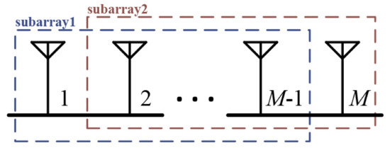
Figure 2.
Subarray structure for estimation of signal parameters via rotational invariance techniques (ESPRIT) algorithm.
Because the antenna array is a ULA, the distances between the antennas are all the same, and there is a phase delay between subarray1 and subarray2, which is corresponding to the distance between the antennas. Therefore, the steering vectors and of each subarray can be expressed using Equation (8).
where and represent a diagonal matrix that accounts for the phase delay between the antennas in each pair, and and are matrices of size .
The signal subspaces and of the two subarrays can be expressed as Equations (9) and (10), respectively, using a nonsingular matrix . Here, is a × matrix, and and are matrices.
From Equations (6)–(10), and can be expressed as Equation (11) below:
where is a × matrix representing , and and have the same eigenvalues. Therefore, the DOA of the received signal can be estimated by calculating the eigenvalue , can be calculated using the least squares method as follows:
From the estimated shown in Equation (12), the eigenvalue can be calculated, and the DOA, , can be calculated as follows:
Hence, the ESPRIT algorithm estimates the DOA using the shift invariances of the two subarrays. However, for antenna arrays with multiple invariance structures, the DOA can be estimated using the MI-ESPRIT algorithm. The MI-ESPRIT algorithm improves the performance of the existing method by changing the antenna array configuration [22,23]. Figure 3 illustrates a case with a multiple invariance structure. The ULA with antennas can be divided into subarrays, and each subarray has a -antenna. In the adjacent subarray, antennas are overlapping, and the number of subarrays and the number of antennas in the subarrays are satisfied as follows:
The signal subspace for subarrays can be expressed as follows.
where represents the steering vector of the first subarray, represents a nonsingular matrix, and represents . By combining the signal subspaces in Equation (15), two new subspaces can be formed, as shown in Equations (16) and (17).
From Equations (16) and (17), and can be expressed as Equation (18) as follows:
The of Equation (18) can be obtained as the following closed-form solution using the least squares method.
After calculating the eigenvalue in the same manner as that in ESPRIT algorithm, and the DOA, , can be calculated as shown in Equation (13).
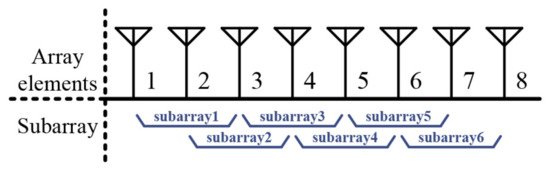
Figure 3.
Subarray structure for multiple invariances (MI)-ESPRIT algorithm ( = 8, = 6, = 3).
2.3. DOA Estimation Technique for Single Target
It is essential that the number of targets is known for the subspace-based DOA estimation algorithm to clearly distinguish the signal subspace and noise subspace from the eigenvector. Therefore, a target detection should be performed before applying the ESPRIT algorithm. In the frequency-modulated continuous wave (FMCW) radar system, a target is detected by searching the peak value in a range-Doppler map (R-D map), and the DOA for each target is estimated thereafter [24,25,26]. Therefore, the ESPRIT algorithm needs to perform DOA estimation only for one target. Moreover, because the power of the signal is concentrated, and the power of the noise is distributed in the R-D map through the FFT operation, there is no degradation in performance even if the ESPRIT operation is performed for one peak value of the R-D map, that is when the number of snapshots is set to one [27]. Figure 4 illustrates the root mean square error (RMSE) of ESPRIT algorithm with the signal-to-noise ratio (SNR) for the targets detected in the R-D map. While estimating the DOA for the targets detected in the R-D map, it is observed that the performance is the same regardless of the number of snapshots. Therefore, in this study, we designed a processor that can support the ESPRIT algorithm for one snapshot.
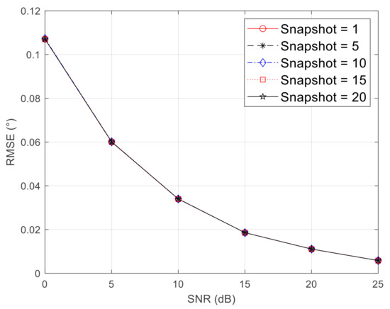
Figure 4.
Comparison of root mean square error (RMSE) of direction-of-arrival (DOA) according to the number of the snapshot for the target detected in the R-D map.
2.4. Comparison of RMSE Performance According to the Number of Antennas
The number of antennas required in the successful implementation of the MI-ESPRIT algorithm must be greater than or equal to four. For a system with four antennas, two subarrays can be configured by setting the number of antennas in the subarray to three for the ESPRIT algorithm. In the same instance, three subarrays can also be configured by setting the number of antennas in the subarray to two for the MI-ESPRIT algorithm. Figure 5 shows the RMSE with SNR according to the number of antennas in the subarray. When the total number of antennas is four, as shown in Figure 5a, there is no difference in performance according to the subarray configuration. However, as shown in Figure 5b, when the total number of antennas is eight, optimal performance can be achieved by setting the number of antennas to three, configuring six sub-arrays, and applying the MI-ESPRIT algorithm. Therefore, in this study, the number of antennas in the subarray is selected as three, we designed an ESPRIT processor that uses the ESPRIT algorithm to estimate the DOA when the total number of antennas is less than four and uses the MI-ESPRIT algorithm to estimate the DOA when the total number of antennas is five or more.
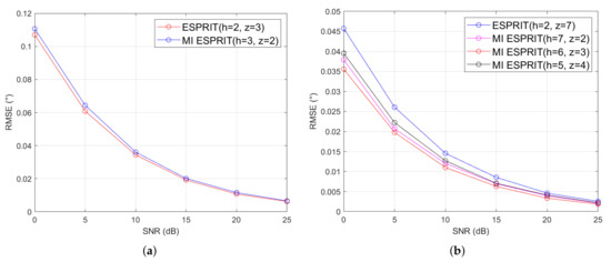
Figure 5.
Comparison of RMSE of DOA according to the number of subarrays () and the number of antennas in subarray (), (a) = 4, (b) = 8.
3. Hardware Architecture of Proposed ESPRIT Processor
Figure 6 shows a block diagram of the proposed ESPRIT processor, which supports a scalable number of antennas. The hardware architecture of the proposed ESPRIT processor consists of a covariance matrix module (CMM), an eigenvalue decomposition module (EDM), a least square module (LSM), and an angle estimation module (AEM). The sequence of operations of the proposed hardware architecture is as follows. First, the signals of the target data detected from the R-D map are entered into the CMM according to the number of antennas, and the covariance matrix is calculated thereafter. After the covariance matrix operation is completed, a data matrix of size × is entered into the EDM, and the eigenvalue decomposition operation is performed. When the eigenvalue decomposition is complete, the signal subspace is output from the EDM, and the LSM performs a least-squares operation according to the number of antennas. The resultant output of the LSM is entered into the AEM to estimate the DOA of the target.
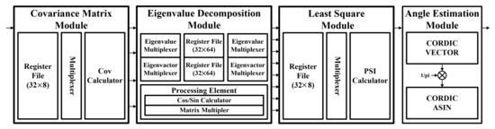
Figure 6.
Hardware architecture of proposed ESPRIT processor.
3.1. Covariance Matrix Module (CMM)
The hardware architecture of the CMM is illustrated in Figure 7 and is composed of a register file (RF), multiplexer, covariance calculator (Cov calculator), and CMM controller. The target data entered in accordance with the number of antennas is stored in a register, and the multiplexer aligns the data according to the number of antennas and transfers it to a Cov calculator that performs a 2 × 2 multiplication operation to perform the covariance operation according to Equation (5). Equations (20) and (21) represent the calculation of Equation (5) when the number of antennas is set to four and eight, respectively.
where , , , and . When the number of antennas is four, the covariance matrix operation result can be obtained through four 2 × 2 matrix multiplication operations; when the number of antennas is eight, the covariance matrix operation result can be obtained through 16 2 × 2 matrix multiplication operations. This indicates that it is possible to support the number of scalable antennas by repeating the matrix multiplication operation according to the number of antennas.
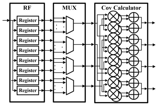
Figure 7.
Hardware architecture of covariance matrix module (CMM).
3.2. Eigenvalue Decomposition Module (EDM)
The cyclic Jacobi method is an EVD algorithm, that is simultaneously used for obtaining all eigenvalues and eigenvectors of the Hermitian matrix through iterative operations. It performs plane rotation by repeatedly multiplying the × Hermitian matrix and the rotation matrix , where is expressed as Equation (22) below:
means the rotation of the plane with respect to the matrix , and the rotation matrix is sequentially rotated like , , , ⋯, and is called the cyclic Jacobi method. When performing the cyclic Jacobi method, is expressed in Equation (23).
When the iterative operation is performed, the matrix converges in the form of a diagonal matrix and represents eigenvalue, represents eigenvector and is expressed as Equation (24) below.
When the elements in row and column of matrix are expressed as , and of the rotation matrix are expressed as Equations (25) and (26), respectively.
Accordingly, the designed EDM generates a signal subspace by performing an eigenvalue decomposition operation on the × data matrix for which the covariance matrix operation is performed according to the number of antennas. The rotation matrix only affects the 2 × 2 matrix multiplication operation, and each multiplication operation is independent. Shahshahani designed a scalable EVD processor based on the independent feature of the multiplication of the Jacobi method [28]. Therefore, in this study, a scalable EDM was designed using the architecture proposed by Shahshahani, as shown in Figure 8. We used a processing element (PE), an eigenvalue multiplexer, and an eigenvector multiplexer. PE performs the matrix multiplication operation after obtaining a rotation matrix. A cos/sin calculator is used to obtain the rotation matrix, and a matrix multiplier module is used for the multiplication operation. To find the rotation matrix, the angle of the input data should be obtained, and the cosine and sine values should be determined according to the obtained angle. The cos/sin calculator uses the coordinate rotation digital computer (CORDIC) vector module and the CORDIC rotation module to calculate the rotation matrix. Subsequently, the matrix multiplier performs a matrix multiplication operation between the input and rotation matrices. The output matrix of the PE aligns the data in the order required for the next iteration through the eigenvalue multiplexer and eigenvector multiplexer. When the iteration process is repeated according to the number of antennas, the signal subspace is the output.
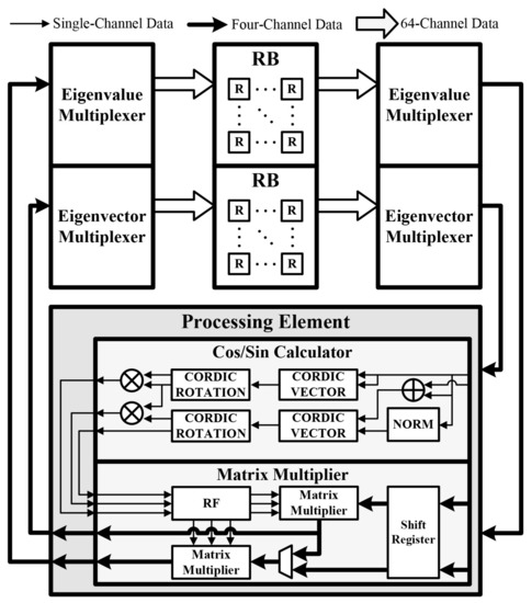
Figure 8.
Hardware architecture of eigenvalue decomposition module (EDM).
The cyclic Jacobi method repeats the process in Equations (22)–(26), and the number of iterations to be repeated is . Thus, as the number of antennas increases, the computational complexity of the cyclic Jacobi method increases dramatically. However, because the angle is estimated for each target in the R-D map, the ESPRIT processor only needs to perform an angle estimation operation on one target. Thus, when the number of targets is one, the signal subspace corresponds to the first column of the eigenvector. Therefore, the rotation matrices needed to compute the first column of the eigenvectors are , , , ⋯, , and the number of iterations performed in operation is . When the number of targets is one, the number of iterations of the cyclic Jacobi method, which has a considerable computational complexity in the ESPRIT algorithm, can be significantly reduced.
In addition, the number of cycles of the proposed EDM needed to perform one iteration in the cos/sin calculator is 46, and two cycles are required to perform a 2 × 2 matrix multiplication operation once. Thus, it takes 48, 50, 50, 52, 52, 54, and 54 cycles each for two, three, four, five, six, seven, and eight antennas. Therefore, the proposed cyclic Jacobi method significantly reduced the number of cycles required to perform EVD operations as compared to the conventional method. As shown in Table 1, the cycle is reduced by up to 75% for two to eight antennas.

Table 1.
Comparison of the cyclic Jacobi method cycles according to the number of antennas.
3.3. Least Square Module (LSM)
When the number of targets is one in the ESPRIT processor because in Equation (12) is a 1 × 1 matrix, = is established; thus, the process of eigenvalue decomposition is unnecessary. In addition, because is a real number, the arg() operation in Equation (13) remains unaffected. Thus, when the number of targets is one, Equation (12) can be simplified as shown in Equation (27).
The hardware architecture of LSM is as shown in Figure 9, and consists of an RF, multiplexer, PSI () calculator, and LSM controller. The signal subspace entered according to the number of antennas is stored in an RF. After aligning the data according to the subarray configuration of Equation (15) using a multiplexer, we enter it into the PSI calculator to perform the operations in Equation (27). The PSI calculator consists of a matrix multiplication module and a complex adder, so it is designed to support a scalable number of antennas. Equations (28) and (29) represent Equation (27) when the number of antennas is set to four and eight, respectively.
where , , , , , and . When the number of antennas is set to four, can be obtained through a single matrix multiplication operation; when the number of antennas is set to eight, can be obtained by performing five matrix multiplications, and the calculation results are added thereafter. Thus, the number of scalable antennas is supported by repeating the matrix multiplication operation according to the number of antennas.
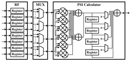
Figure 9.
Hardware architecture of least square module (LSM).
3.4. Angle Estimation Module (AEM)
When the number of targets is one in the ESPRIT processor, the DOA can be estimated using Equation (30) without the eigenvalue decomposition of .
Therefore, the AEM module calculates Equation (30) and estimates the DOA of a target using the obtained from the LSM. The hardware architecture of the AEM is shown in Figure 10. It is composed of the CORDIC vector module and CORDIC ASIN module. The AEM calculates the angle of using the CORDIC vector module and estimates the DOA of a target using the CORDIC ASIN module.
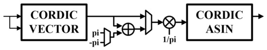
Figure 10.
Hardware architecture of angle estimation module (AEM).
4. Implementation Results of Proposed ESPRIT Processor
The proposed ESPRIT processor was designed using the hardware description language (HDL), and it was implemented on a Xilinx Zynq UltraScale+ ZCU104 system-on-chip (SoC) platform [29]. Table 2 shows the implementation results of the proposed ESPRIT processor. The proposed ESPRIT processor was implemented with 28,978 LUTs, 11,279 FFs, and 374 DSPs, and it was confirmed that it could be implemented with an operating frequency of up to 334 MHz. In addition, as shown in Figure 11, the proposed ESPRIT processor was configured on the SoC platform using the advanced extensible interface (AXI) bus interface to perform real-time verification. Figure 12 shows the verification environment for the SoC platform. The target data for hardware verification were initialized in the double data rate (DDR) memory, and the number of antennas was set using a microprocessor unit (MPU). Subsequently, when the start signal of the ESPRIT processor was entered through the MPU, the initialized data in the DDR memory were stored in the SRAM of the ESPRIT processor through the master interface channel, and then the ESPRIT processor was operated. Subsequently, the result of the ESPRIT processor was output to the Host-PC through the universal asynchronous receiver/transmitter (UART) interface to confirm the result of the DOA estimation. From Table 2, it was confirmed that the execution time for two to eight antennas was 0.39–1.86 s.
Table 2.
Implementation results of proposed ESPRIT processor based on Xilinx Zynq UltraScale+ ZCU104 FPGA.
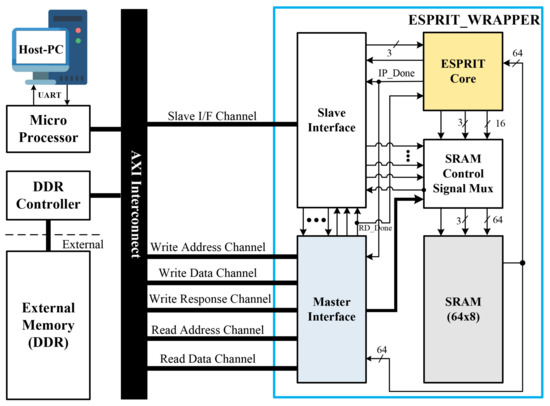
Figure 11.
System architecture of the proposed ESPRIT processor.
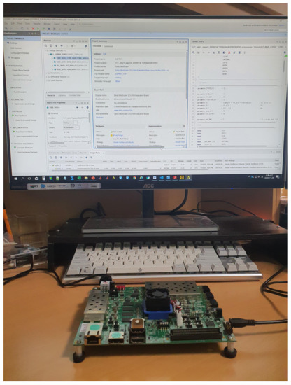
Figure 12.
Verification environment using system-on-chip (SoC) platform.
Table 3 shows the comparison results of the hardware complexity between the proposed ESPRIT processor and the designs in [18,19,30,31]. For a fair comparison, the proposed ESPRIT processor was implemented on a Xilinx Virtex-5 XC5VSX95T FPGA, and the execution time, processing rate, and area efficiency were compared for a configuration with four antennas. In [18], an ESPRIT processor was designed using QR decomposition to implement an ESPRIT processor with low complexity. The LU decomposition was used in [19] for reducing the complexity, as compared to the ESPRIT processor using the QR decomposition method. The Cholesky-based DOA estimation processor presented in [30] does not require the EVD to be calculated, so it has less computational complexity than EVD-based DOA algorithms. Additionally, the DOA estimation processor using the Bartlett algorithm presented in [31] is a spectral-based method, and it is known that the computational complexity is smaller than that of the MUSIC or ESPRIT processor. However, the ESPRIT processor of the four references still has a high hardware complexity and supports only four or eight antennas. On the other hand, the proposed ESPRIT processor supported a scalable number of antennas, and it can be seen that the area efficiency (Hz/Registers, Hz/LUTs) was higher than that of [18,19,30,31]. As compared to the efficiency of the configuration in [18], the efficiency of the register was approximately 45.74 times higher, and that of the LUT was approximately 28.71 times higher. Compared to the configuration in [19], the register was approximately 2.21 times higher, and the LUT was 1.68 times higher. Additionally, in [30], the register was approximately 2.84 times higher, and the LUT was 1.99 times higher. As compared to the design in [31], the area-efficiency for register of the proposed design was about 25.59 times higher and that for LUT was about 10.38 times higher. In particular, the execution time of the DOA estimation processor presented in [31] took about 24.78 times longer than the proposed ESPRIT processor.
Table 3.
Comparison of the proposed ESPRIT processor with previous research results.
5. Conclusions
In this paper, we proposed a scalable ESPRIT processor that supports two to eight scalable hardware antennas. The proposed ESPRIT processor is based on the MI-ESPRIT structure. The performance of the proposed ESPRIT processor is improved by using multiple invariances of the array, and the complexity is reduced by simplifying the least-squares method. Moreover, the execution time is reduced by decreasing the cyclic Jacobi method, which has the most significant computational complexity for calculating the EVD in ESPRIT. In addition, the proposed ESPRIT processor was implemented on a Xilinx Zynq UltraScale+ SoC Platform, and it was confirmed that it can support real-time processing. The proposed ESPRIT processor was implemented with 28,978 LUTs, 11,279 FFs, and 374 DSPs with an operating frequency of up to 334 MHz. Additionally, the proposed ESPRIT processor is implemented on a Xilinx Virtex-5 FPGA for a fair comparison of the hardware complexity between the existing DOA estimation processor and the proposed ESPRIT processor. It was confirmed that the proposed ESPRIT processor is superior to the exisiting DOA estimation processors in terms of area efficiency. Therefore, the proposed ESPRIT processor is expected to be one of good solutions for estimating DOA in FMCW radar systems.
Author Contributions
Y.J. (Yongchul Jung) designed the ESPRIT processor, performed the simulation and experiment, and wrote the paper. H.J. and S.L. implemented the processor and revision of this manuscript. Y.J. (Yunho Jung) conceived of and led the research, analyzed the experimental results, and wrote the paper. All authors read and agreed to the published version of the manuscript.
Funding
This work was supported by the Institute of Information & communications Technology Planning & Evaluation (IITP) grant funded by Korean government (MSIT) (No. 2017-0-00528, 2019-0-00056), and the CAD tools were supported by IDEC.
Conflicts of Interest
The authors declare no conflict of interest.
References
- You, G.H.; Qiu, T.S.; Yang, J. A novel DOA estimation algorithm of cyclostationary signal based on UCA in impulsive noise. AEU Int. J. Electron. Commun. 2013, 67, 491–499. [Google Scholar] [CrossRef]
- Luo, J.; Zhang, G.; Yu, K. An automatically paired two-dimensional direction-of-arrival estimation method for two parallel uniform linear arrays. AEU Int. J. Electron. Commun. 2017, 72, 46–51. [Google Scholar] [CrossRef]
- Li, J.; Jiang, D.; Zhang, X. DOA estimation based on combined unitary ESPRIT for coprime MIMO radar. IEEE Commun. Lett. 2016, 21, 96–99. [Google Scholar] [CrossRef]
- Gu, Y.; Zhang, Y.D.; Goodman, N.A. Optimized compressive sensing-based direction-of-arrival estimation in massive MIMO. In Proceedings of the IEEE International Conference on Acoustics, Speech and Signal Processing (ICASSP), New Orleans, LA, USA, 5–9 March 2017; pp. 3181–3185. [Google Scholar]
- Schmidt, R. Multiple emitter location and signal parameter estimation. IEEE Trans. Antennas Propag. 1986, 34, 276–280. [Google Scholar] [CrossRef]
- Roy, R.; Kailath, T. ESPRIT-estimation of signal parameters via rotational invariance techniques. IEEE Trans. Acoust. Speech Signal Process. 1989, 37, 984–995. [Google Scholar] [CrossRef]
- Cui, L.; Zhang, Y.; Jiao, Y. Two-dimensional MUSIC Spectral Peak Search Algorithm Based on Improved Chicken Swarm Optimization. In Proceedings of the 2019 IEEE International Conference on Signal Processing, Communications and Computing (ICSPCC), Dalian, China, 20–22 September 2019; pp. 1–5. [Google Scholar]
- Li, W.; Liao, W.; Fannjiang, A. Super-resolution limit of the ESPRIT algorithm. IEEE Trans. Inf. Theory 2020, 66, 4593–4608. [Google Scholar] [CrossRef]
- Steinw, T.J.; Roemer, F.; Haardt, M. Second-order performance analysis of Standard ESPRIT. In Proceedings of the 2017 IEEE International Conference on Acoustics, Speech and Signal Processing (ICASSP), New Orleans, LA, USA, 5–9 March 2017; pp. 3051–3055. [Google Scholar]
- Roy, R.; Paulraj, A.; Kailath, T. ESPRIT—A subspace rotation approach to signal parameter estimation. IEEE Trans. Acoust. Speech Signal Process. 1986, 34, 1340–1342. [Google Scholar] [CrossRef]
- Baig, N.A.; Malik, M.B. Comparison of direction of arrival (DOA) estimation techniques for closely spaced targets. Int. J. Future Comput. Commun. 2013, 2, 654–659. [Google Scholar] [CrossRef]
- Zhou, L.; Haung, D.; Duan, H.; Chen, Y. A modified ESPRIT algorithm based on a new SVD method for coherent signals. In Proceedings of the 2011 IEEE International Conference on Information and Automation, Shenzhen, China, 6–8 June 2011; pp. 75–78. [Google Scholar]
- Gupta, P.; Verma, V.K.; Senapati, V. Angle of arrival detection by ESPRIT method. In Proceedings of the 2017 International Conference on Communication and Signal Processing (ICCSP), Chennai, India, 6–8 April 2017; pp. 1143–1147. [Google Scholar]
- Dhope, T.S. Application of MUSIC, ESPRIT and Root MUSIC in DOA estimation. World J. Sci. Technol. 2011, 1, 20–25. [Google Scholar]
- Oumar, O.A.; Siyau, M.F.; Sattar, T.P. Comparison between MUSIC and ESPRIT direction of arrival estimation algorithms for wireless communication systems. In Proceedings of the The First International Conference on Future Generation Communication Technologies, London, UK, 12–14 December 2012; pp. 99–103. [Google Scholar]
- Zhang, X.; Gao, X.; Xu, D. Multi-invariance ESPRIT-based blind DOA estimation for MC-CDMA with an antenna array. IEEE Trans. Veh. Technol. 2009, 58, 4686–4690. [Google Scholar] [CrossRef]
- Xu, Y.; Liu, Z. Closed-form multiple invariance ESPRIT. Multidimens. Syst. Signal Process. 2007, 18, 47–54. [Google Scholar] [CrossRef]
- Alhamed, A.; Tayem, N.; Alshawi, T.; Alshebeili, S.; Alsuwailem, A.; Hussain, A. FPGA-based real-time implementation for direction-of-arrival estimation. J. Eng. 2017, 6, 260–265. [Google Scholar] [CrossRef]
- Hussain, A.A.; Tayem, N.; Butt, M.O.; Soliman, A.H.; Alhamed, A.; Alshebeili, S. FPGA hardware implementation of DOA estimation algorithm employing LU decomposition. IEEE Access 2018, 6, 17666–17680. [Google Scholar] [CrossRef]
- Guenther, D.; Leupers, R.; Ascheid, G. A Scalable, Multimode SVD precoding ASIC based on the Cyclic Jacobi Method. IEEE Trans. Circuit Syst. Regul. Pap. 2016, 63, 1283–1294. [Google Scholar] [CrossRef]
- Alessandrini, M.; Biagetti, G.; Crippa, P.; Falaschetti, L.; Manoni, L.; Turchetti, C. Singular Value Decomposition in Embedded Systems Based on ARM Cortex-M Architecture. Electronics 2021, 10, 34. [Google Scholar] [CrossRef]
- Cui, K.; Wu, W.; Huang, J.; Chen, X.; Yuan, N. DOA estimation of LFM signals based on STFT and multiple invariance ESPRIT. AEU Int. J. Electron. Commun. 2017, 77, 10–17. [Google Scholar] [CrossRef]
- Lin, J.; Ma, X.; Yan, S.; Hao, C. Time-frequency multi-invariance ESPRIT for DOA estimation. IEEE Antennas Wirel. Propag. Lett. 2015, 15, 770–773. [Google Scholar] [CrossRef]
- Hyun, E.; Lee, J. Moving target range detection algorithm for FMCW radar. In Proceedings of the 2013 14th International Radar Symposium (IRS), Dresden, Germany, 19–21 June 2013; pp. 758–761. [Google Scholar]
- Dzvonkovskaya, A.L.; Rohling, H. CFAR target detection based on gumbel distribution for HF radar. In Proceedings of the 2006 International Radar Symposium, Krakow, Poland, 24–26 May 2006; pp. 1–4. [Google Scholar]
- Tang, T.; Wu, C.; Elangage, J. Analyze the FMCW Waveform Skin Return of Moving Objects in the Presence of Stationary Hidden Objects using Numerical Models. Electronics 2021, 10, 28. [Google Scholar] [CrossRef]
- Park, G.H.; Seo, Y.K.; Kim, H.N. Range-Doppler Domain-Based DOA Estimation Method for FM-Band Passive Bistatic Radar. IEEE Access 2020, 8, 56880–56891. [Google Scholar] [CrossRef]
- Shahshahani, S.M.R.; Mahdiani, H.R. A High-Performance Scalable Shared-Memory SVD Processor Architecture Based on Jacobi Algorithm and Batcher’s Sorting Network. IEEE Trans. Circuit Syst. Regul. Pap. 2020, 67, 1912–1924. [Google Scholar] [CrossRef]
- UltraSclae+ ZCU104 Overview. Available online: https://www.xilinx.com/products/boards-and-kits/zcu104.html#overview (accessed on 20 February 2021).
- Hussain, A.A.; Tayem, N.; Soliman, A.H.; Radaydeh, R.M. FPGA hardware implementation of Computationally Efficient Multi-Source DOA Estimation Algorithms. IEEE Access 2019, 7, 88845–88858. [Google Scholar] [CrossRef]
- Abusultan, M.; Harkness, S.; LaMeres, B.J.; Huang, Y. FPGA implementation of a Bartlett direction of arrival algorithm for a 5.8ghz circular antenna array. In Proceedings of the 2010 Aerospace Conference, Big Sky, MT, USA, 6–13 March 2010; pp. 1–10. [Google Scholar]


Publisher’s Note: MDPI stays neutral with regard to jurisdictional claims in published maps and institutional affiliations. |
© 2021 by the authors. Licensee MDPI, Basel, Switzerland. This article is an open access article distributed under the terms and conditions of the Creative Commons Attribution (CC BY) license (http://creativecommons.org/licenses/by/4.0/).