Article

Multi-Level Switching of Al-Doped HfO2 RRAM with a Single Voltage Amplitude Set Pulse

Key Laboratory for Wide Band Gap Semiconductor Materials and Devices of Education, The School of Microelectronics, Xidian University, Xi’an 710071, China
*
Author to whom correspondence should be addressed.
Electronics 2021, 10(6), 731; https://doi.org/10.3390/electronics10060731
Submission received: 19 February 2021 / Revised: 12 March 2021 / Accepted: 15 March 2021 / Published: 19 March 2021
(This article belongs to the Special Issue RRAM Devices: Materials, Designs, and Properties)

Abstract

:
In this paper, the resistive switching characteristics in a Ti/HfO2: Al/Pt sandwiched structure are investigated for gradual conductance tuning inherent functions. The variation in conductance of the device under different amplitudes and voltage pulse widths is studied. At the same time, it was found that the variation in switching parameters in resistive random-access memory (RRAM) under impulse response is impacted by the initial conductance states. The device was brought to a preset resistance value range by energizing a single voltage amplitude pulse with a different number of periodicities. This is an efficient and simple programming algorithm to simulate the strength change observed in biological synapses. It exhibited an on/off of about 100, an endurance of over 500 cycles, and a lifetime (at 85 °C) of around 105 s. This multi-level switching two-terminal device can be used for neuromorphic applications to simulate the gradual potentiation (increasing conductance) and inhibition (decreasing conductance) in an artificial synapse.

1. Introduction

Resistive switching (RS) devices were originally conceived for memory applications [1,2] because of the advantages compared to traditional charges-based memories, such as their superior speed, low operating voltage, excellent scalability [3], and non-volatile and multi-level data storage abilities [4]. Currently, multi-level resistive random-access memory (RRAM) devices can be widely used for data storage [5,6], logical calculation [7,8], bionic neural network systems [9,10], and so on. They have also been studied as artificial synapses for applications in neuromorphic computation, featuring high parallelism [11,12,13] and the ability to perform adaptive learning [14]. RRAM devices can solve problems that the traditional Von Neumann paradigm is not able to deal with, such as incomplete defined inputs, as in real-world scenarios [15], or the implementation of adaptive learning algorithms [14].
Great efforts have been made to optimize both materials and programming techniques to design a device that can simulate biological synaptic behavior, i.e., gradually increase and decrease its conductance under suitable voltage excitation [13,15,16]. In order to facilitate the practical applications of multi-level RRAM devices, it is necessary to consider the materials of complementary metal oxide silicon (CMOS)-compatible devices. HfO2 is used as a high-k gate dielectric in CMOS devices because of its high reliability, fast operating speed, and low power consumption [17,18]. Currently, analog switching with multi-level states and reliability is not available for RRAM. Therefore, researchers have come up with a variety of solutions, including improving the manufacturing process (doping in the HfO2 layers [19,20,21,22,23], modulation of oxide/metal interfaces [9,24], post-deposition annealing [19], etc.) and optimizing the measurement conditions. For electrode materials, Hong et al. [9] suggested that the use of a combination of inert and active metals, such as Ti/Pt, could improve the reliability of the device. Traore et al. [24] found that a Ti/HfO2 interface facilitates the formation of O defects from the interface region into Ti and suggest the interface region to be the precursor for defect formation. Previous studies [20,21,22,23] have shown that the doped HfO2 RRAM devices are more likely to realize stable intermediate-resistance states (IRS) together with high-resistance states (HRS) and low-resistance states (LRS) compared with pure HfO2 devices. It was attributed to controllable oxygen vacancies (Vo)-based filament formation along the Al atoms diffused into the HfO2 resistive switching film [21]. Wang et al. [4], Gao et al. [25], and Covi et al. [20] prepared multi-level RRAM by doping HfO2 with Cu, Gd, and Al, respectively. However, they can only carry out a four-level storage state [4,25]. According to Zhou et al. [26], TiN/Al2O3/HfO2/Pt bi-layer RRAM devices show seven analog reset states for both current scanning and voltage scanning operations with an on/off ratio of around 10. Woo et al. [27] explained that RRAM devices with an AlOx/HfOx bi-layer structure present 12 distinct analog multi-levels with on/off ratio over 10. Moreover, the different conductance states were achieved using the application of voltage pulses with different amplitudes [12,26,28] or widths [10,13,28] or compliance currents of different flexibilities [4] during the set program process. This will increase the operational difficulty in the above applications. Few scholars have realized that the device can reach a certain conductivity range accurately through a train of identical pulses [29], which has a simple structure that facilitates a highly integrated implementation and is therefore best suited for neuromorphic applications. In addition, it was reported that the reset operation usually features a gradual change in the device conductance. The resistive switching is inherently stochastic due to the randomness of the generation and the migration of oxygen vacancy based on the Kinetic Monte Carlo simulation proposed by Yu et al. [29]. The sudden change in conductivity in the set process requires an additional current compliance [12,15,30,31] to prevent device damage, which is the problem that must be overcome to realize the above scheme.
In this context, an Al-doped HfO2-based memristor is presented as a suitable device for an artificial synapse. We previously studied the mechanism of multi-stage resistance of a HfO2: Al memristor [23]. This time, by studying different switching dynamics in the pulsed regime, a scheme was obtained through which the device can be stabilized to the desired conductivity range by using a series of identical pulses. Firstly, the device was obtained by cyclic growth of HfO2 and Al2O3 in a certain proportion by an atomic layer deposition (ALD) reactor. Then, the resistive switching characteristics of the device were analyzed by direct current (DC) scanning and voltage pulses. Finally, by matching the appropriate pulse and initial conductance values, the device conductance could be gradually changed stepwise with the set pulses.

2. Materials and Methods

The samples studied here are Ti/HfO2: Al/Pt (Figure 1a) RRAM devices. Ti/Pt layers of 120 nm were successively deposited by sputtering at room temperature on a Si/SiO2 substrate. Ti acts as the adhesive layer between the bottom electrode (BE) of Pt and the substrate. After this, a 20-nm HfO2 layer was deposited on Pt/Ti/SiO2-coated silicon substrates in an ALD reactor at 300 °C [32]. Al-doped films were obtained by depositing one cycle of Al2O3 for every 33 cycles of HfO2. The thicknesses of the thin films were measured using a spectroscopic ellipsometer (J.A. Woollam Co.SE M2000U, Lincoln, NE, USA), and the measured result was about 19.73 nm. Finally, a Ti layer of 50 nm acting as a top electrode (TE) and a Pt layer of 100 nm acting as covering layers were deposited by DC sputtering and patterned to form a 100 μm × 100 μm isolated square (Figure 1b). The Al atomic concentration was 1.81%. According to the chemical binding energy analysis of the film by X-ray photoelectron spectroscopy of the Theta 300 XPS system, the atomic concentration of Al was 1.81%. Figure 1c,d show the spectra of Al-doped and non-doped devices. The spectra were calibrated by C 1 s (284.6 eV) peak. For the HfO2 film, the peak of Hf 4f can be fitted as a double peak. Through fitting, it can be seen that the ratio of Hf 4f5/2 to Hf 4f7/2 increased for the doped devices. Moreover, Al-doped devices show the shift of the Hf 4f peak to the higher binding energy and a distinct 74.3 eV peak of Al 2p.
Electrical measurements were performed using Agilent B1500A (Agilent, Santa Clara, CA, USA). The Source Measurement Unit (SMU) was used to perform the DC sweeps, and the Waveform Generator/Fast Measurement Unit (WGFMU) was used to perform pulse signals generation and measurement. The signal needle of the two modules contacted the TE of the device simultaneously, and the working module was selected at the operation interface of the testing equipment [25]. Then, the selected module generated corresponding electrical signals that were applied to the device. The bottom electrode was always grounded.

3. Results and Discussion

3.1. Direct-Current Characteristics

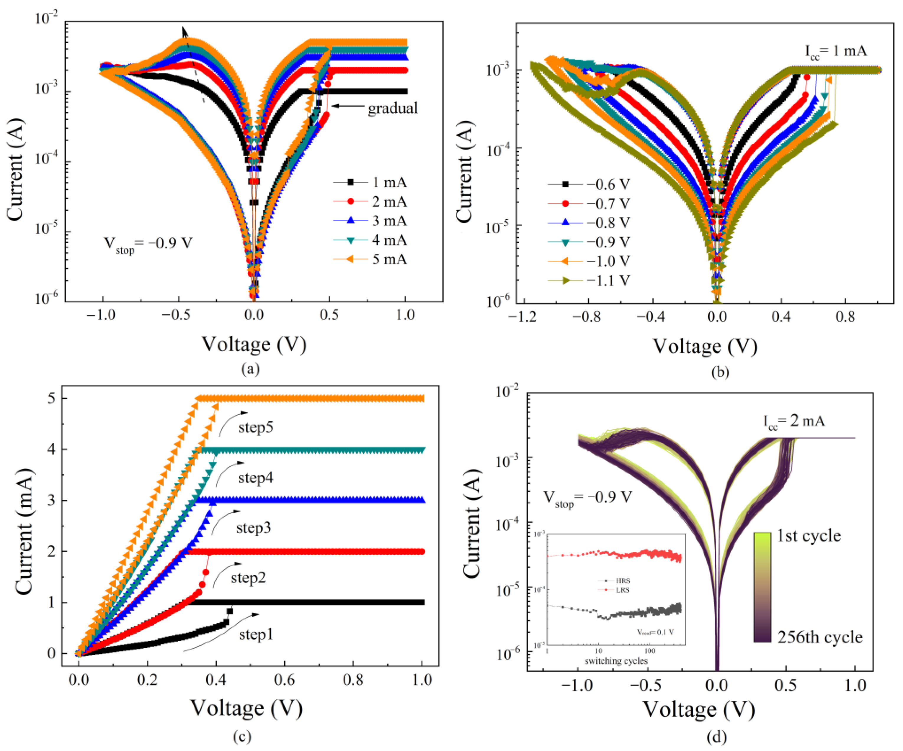
Figure 2 shows typical DC I-V bipolar switching curves of Al-doped HfO2-based RRAM devices. In the set/reset process, multi-stage conductance was obtained by changing the compliance current and the stop voltage, respectively. It was found that both the set (off-to-on transition) process and the reset (on-to-off transition) process are gradual. This is because Al dopants reduce the formation energy of oxygen vacancies (Vo) and Vo are formed scattered near the dopants [33]. Therefore, multiple filaments are formed in the set process based on the uniform distributed Vo in the oxide layer [9,21,34]. It can also be seen that the set voltage increases obviously with the increase in the reset stop voltage. It shows that with the increase in the reset stop voltage, the more oxygen vacancies in the oxide layer are consumed, the more serious the damage to the conductive filaments. At this point, the set process requires a larger forward voltage to reform the conductive filaments in the oxide layer. In contrast, the reset voltage does not obviously change with the increase in the set limiting current. In the reset process, regardless of the original resistance, the conductive filament will break when the reverse voltage applied to the TE of the device reaches a certain value. This shows that the difference in conductive filaments in different low-resistance states is not due to the thickness of filaments, but the number of filaments [21,35].
Figure 2c shows the DC I-V characteristic curve during gradually increasing compliance current in the set process. It can be seen that the device has excellent resistance retention characteristics in the set process and the resistance changes gradually. Combined with Figure 2a, the resistance of the device after the set process of the DC sweep is mainly determined by the compliance current. The multi-step switching effect is demonstrated by increasing the current compliance step by step [36]. The Vo generated by the reapplied positive bias voltage forms more conductive filaments as the limiting current increases. Therefore, the set process may present as a gradual change in resistance. Figure 2d shows the DC I-V curve for the first 256 cycles of the device. It can be seen that the set/reset voltage barely changed, whereas the switching window is slightly reduced. This shows the excellent cyclic repeatability of the device.

3.2. Pulse Characteristic

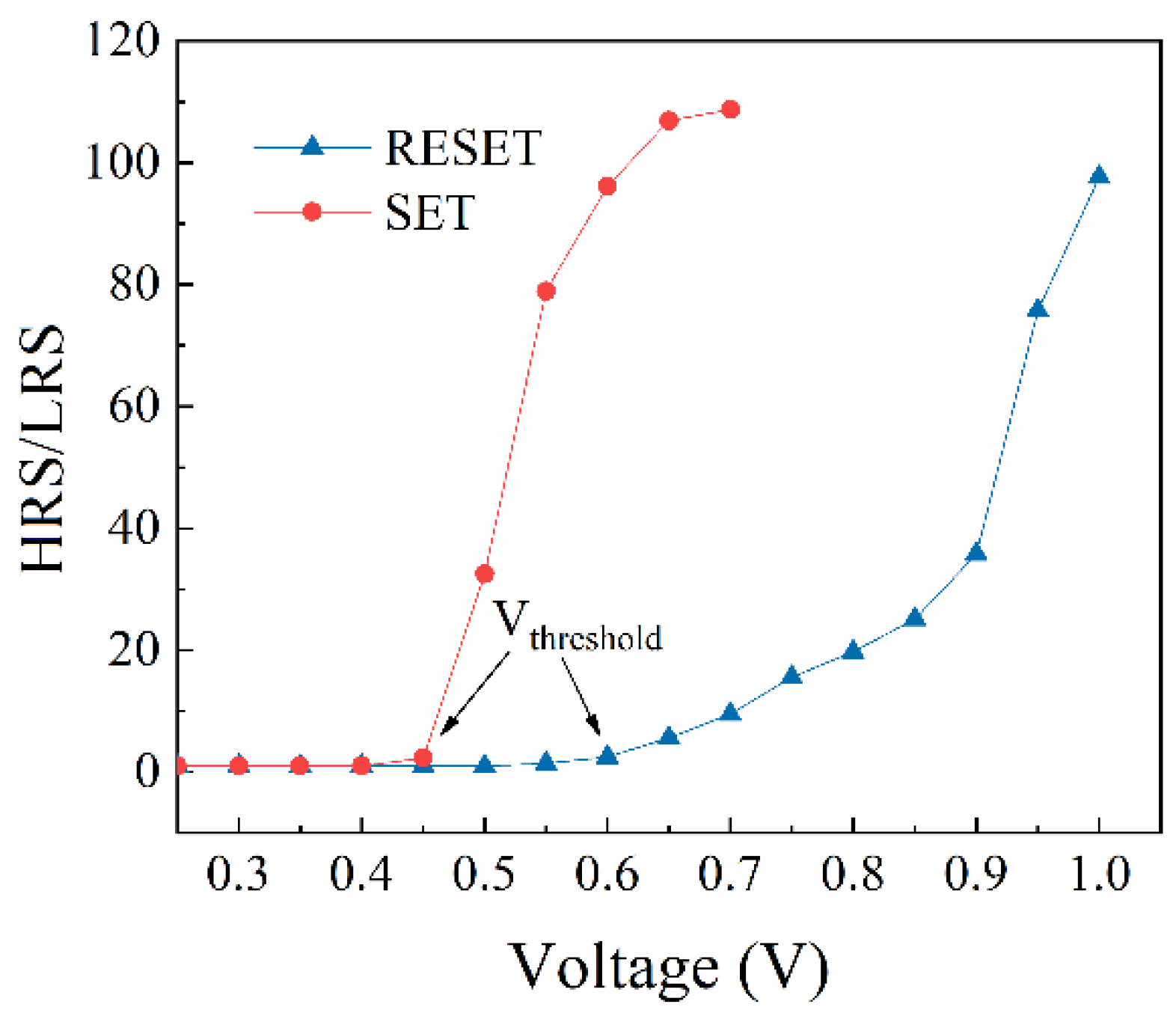
Currently, we turn our attention toward the impulse response of the devices using WGFMU, which is the central exploration of this work. First, the device was set and reset using a square-waveform voltage pulse with a width of 100 μs. Figure 3 shows the resistance window (HRS/LRS for set is Rinitial/Rafter, and for reset is Rafter/Rinitial) variation by applying a single voltage pulse of different amplitudes to a device with the same initial resistance. It can be seen from the figure that when the pulse width is constant, the increase in the voltage amplitude will cause a great variation in the conductance [28]. Both set and reset have a threshold bias level of around Vth ~ 0.45 V and Vth ~ −0.6 V, respectively. When the set voltage reaches 0.6 V, it is limited by current limitation, and the change of resistance is no longer obvious.
The typical dynamic current responses of the voltage pulse are shown in Figure 4. According to the reset process, it can be seen from Figure 4b that the response current of the device suddenly decreases under the impulse voltage. The results of the same reset voltage pulse applied in different resistance states of devices are also compared in the figure. The original resistance state of the device cannot change the mutation of the reset process, but only the time of the reset process. Combined with the above DC characteristics, it is shown that the thickness of several conductive filaments in the oxide layer is the same, and the fracture occurs simultaneously in the reset process. The gradual change in the conductance value during the reset process in the DC sweep is because the bias value applied to the device increases point by point. Multiple conductive filaments will gradually break from various relatively thin places until all the conductive filaments are broken. The conductance modulation of the reset process is suitable for applying voltage pulses with different amplitudes.
Compared to the reset process, the multi-stage set process is easier to implement. It can be observed from Figure 4a that the transient current of the device increases gradually under continuous constant voltage. This indicates that the change in resistance of the device during the set process is gradual. This, in combination with Figure 2a above, led to the conclusion that the resistance change process is the process through which the conductive filaments are formed in the oxide layer one by one. With the gradual switch performance of the memory unit, multi-bit data storage can be easily implemented under an optimized switching operation scheme. Thus, we utilized the gradual set process to obtain multi-stage resistance states.
According to Figure 4a, the current of the set voltage at 0.55 V, 0.6 V, and 0.65 V are all gradients. However, the trends of the current curve are significantly different. According to Figure 3, the larger the set voltage, the larger the resistance window. However, it can be found from Figure 4a that the trend of current change is too fast under an excessive set voltage, which is not conducive to the multi-resistance state. Combining Figure 3 and Figure 4a, when the set voltage is 0.6 V, there is a sufficiently large resistance change window, and the changing trend of current is balanced throughout the set process, which is the most suitable set pulse voltage.
Then, the excitation pulse width was reduced properly. Figure 5 shows the typical dynamic current response of a 0.6 V amplitude, 10 μs pulse width, and square-waveform voltage pulse. It can be seen that different initial resistance values have a large influence on the change in resistance values in the set process [37]. The three HRS listed in figure correspond to the reset stop voltages of −0.9 V (black), −1.0 V (red), and −1.1 V (blue). When the initial resistance is larger, the conductance changes more sharply. This may be the result of the complete destruction of the conducting filaments of the device under the extremely low conductivity [30,38]. This makes the oxygen vacancy more disorganized in the oxide layer. The oxygen vacancy concentration is very high in the local part of the filament structure, which is composed of oxygen vacancies. In the case of equivalent oxygen vacancies, at this point, the distribution of oxygen vacancies throughout the dielectric layer is more uniform than when the partially conducting filament is maintained. The oxygen vacancy concentration in the outer space of the conductive filament in the dielectric layer is much lower than in the higher conductivity state, in which the oxygen vacancy is more disordered. According to the transport model, when the applied electric field intensity is the same, the greater the concentration of ions, the greater the transport flux. Under the excitation of the set pulse, the oxygen vacancy can be recombined more quickly to form conductive filaments that are different from those before the reset process. When the device is in a high configuration, in which the conductive filament has just broken, the conductive filament retains its integrity except for the broken parts. During the set process, the conductive filaments are restored one by one at the break to form the original conductive filament.
Therefore, it is particularly important to select and fix the resistance state before applying the pulse in order to obtain a specific stable resistance value in the set process. When the pulse width is 10 μs, the dynamic current of the device reaches saturation at about 30–50 pulse periods. This is not conducive to obtaining more different specific resistance values. It is necessary to further reduce the pulse width in the set process.

3.3. Multi-Level Switching

Finally, we chose the square-waveform voltage pulse signal with a width of 1 μs and an amplitude of 0.6 V as the set pulse. One cycle included 400 consecutive set pulses. To stabilize the initial resistance value in a certain range before the set process, the DC sweep was adopted to complete the reset process of the device. The reset stop voltage was set to −0.9 V. Device conductance is shown as a function of the applied voltage pulse number for ON switching (from HRS to LRS), as shown in Figure 6a. The conductance was measured at 0.1 V after each pulse. The set training process at several milestone cycles in the endurance test is also shown. No significant degradation was found after 500 cycles. Figure 6b shows the box-plot of the conductance of the device at different pulse periods for 100 different devices. After selecting 12 nodes in the set process of 400 pulses, the increment necessary for the pulse period to reach the next resistance state increases. It can be found that under the first 50 set pulses, the conductance of the device is less uniform, and then tends to be concentrated. Although the upper and lower limits of the conductance of each node overlapped partially, the interquartile ranges did not coincide. The set pulse with only a single voltage amplitude was realized to set the device in more than a dozen different resistance states.
For the data retention characteristic, 12 devices were set to preset conductance by respectively applying 1, 2, 5, 10, 20, 40, 70, 110, 160, 220, 300, and 400 set pulses and were kept at 85 °C [39]. Figure 7 shows the retention test of all levels for resistance at 85 °C. The conductance was read every hour with a voltage of 0.1 V. It can be seen that the resistance values of all states were stable and remained unchanged after around 105 s.

4. Conclusions

The HfO2: Al RRAM devices proposed in this paper demonstrated a stable resistance state set/reset performance under DC sweep and gradual set resistance state performance under consecutive voltage pulses. It was found that the conductivity of the devices at high conductivity depends more on the number of conductive filaments than their thickness. The device can stably reach the preset resistance value by applying the same number of pulses in the setting process. Using a single voltage amplitude of pulse throughout the multi-stage resistance adjustment process can simplify the later storage system. These novel devices can be used for realizing complex logic functions. No data were lost over the course of more than a day at 85 °C. The Ti/HfO2: Al/Pt device is a good potential candidate for multi-level storage.

Author Contributions

Conceptualization, J.L. and S.W.; methodology, J.L.; validation, S.W. and J.L.; investigation, J.L. and S.W.; resources, H.L.; data curation, J.L.; writing—original draft preparation, J.L.; writing—review and editing, J.L.; visualization, J.L.; supervision, S.W.; project administration, H.L.; funding acquisition, H.L. All authors have read and agreed to the published version of the manuscript.

Funding

This research was funded by Key Technologies Research on Multilevel Cooperative Suppression for Transient Electromagnetic Interference of Power Master control chip (Grant Nos. 546816190005); National Natural Science Foundation of China, grant number 61434007, and 61376099; the Major Fundamental Research Program of Shaanxi (Grant No.2017ZDJC-26); and the Laboratory Open Fund of Beijing Smart-chip Microelectronics Technology Co., Ltd.

Informed Consent Statement

Informed consent was obtained from all subjects involved in the study.

Data Availability Statement

Data is contained within the article.

Conflicts of Interest

The authors declare no conflict of interest.

References

  1. Beck, A.; Bednorz, J.G.; Gerber, C.; Rossel, C.; Widmer, D. Reproducible switching effect in thin oxide films for memory applications. Appl. Phys. Lett. 2000, 77, 139–141. [Google Scholar] [CrossRef]
  2. Ignatiev, A.; Wu, N.J.; Liu, S.Q.; Chen, X.; Nian, Y.B.; Papaginanni, C.; Strozier, J.; Xing, Z.W. Resistance Switching Memory Effect in Transition Metal Oxide Thin Films. In Proceedings of the 7th Annual Non-Volatile Memory Technology Symposium, San Mateo, CA, USA, 5–8 November 2006; pp. 100–103. [Google Scholar] [CrossRef]
  3. Baek, I.G.; Lee, M.S.; Seo, S.; Lee, M.J.; Seo, D.H.; Suh, D.S. Highly Scalable Nonvolatile Resistive Memory Using Simple Binary Oxide Driven by Asymmetric Unipolar Voltage Pulses. In Proceedings of the IEDM Technical Digest. IEEE International Electron Devices Meeting, San Francisco, CA, USA, 13–15 December 2004; pp. 587–590. [Google Scholar]
  4. Wang, Y.; Liu, Q.; Long, S.; Wang, W.; Wang, Q.; Zhang, M.; Zhang, S.; Li, Y.; Zuo, Q.; Yang, J. Investigation of resistive switching in Cu-doped HfO2 thin film for multilevel non-volatile memory applications. Nanotechnology 2009, 21, 1–6. [Google Scholar] [CrossRef]
  5. Lee, H.Y.; Chen, P.S.; Wu, T.Y.; Chen, Y.S.; Wang, C.C.; Tzeng, P.J. Low Power and High-Speed Bipolar Switching with a Thin Reactive Ti Buffer Layer in Robust HfO2 Based RRAM. In Proceedings of the IEEE International Electron Devices Meeting, San Francisco, CA, USA, 15–17 December 2008; pp. 1–4. [Google Scholar] [CrossRef]
  6. Duan, W.J.; Wang, J.B.; Zhong, X.L. Electrically-controlled nonlinear switching and multi-level storage characteristics in WOx film-based memory cells. J. Phys. Chem. Solids 2018, 116, 148–152. [Google Scholar] [CrossRef]
  7. Zhou, Y.X.; Li, Y.; Su, Y.T.; Wang, Z.R.; Shih, L.Y.; Chang, T.-C.; Chang, K.-C.; Long, S.-B.; Sze, S.M.; Miao, X.-S. Nonvolatile reconfigurable sequential logic in a HfO2 resistive random-access memory array. Nanoscale 2017, 9, 6649–6657. [Google Scholar] [CrossRef]
  8. Lee, G.S.; Kim, G.H.; Kwak, K.; Jeong, D.S.; Ju, H. Enhanced Reconfigurable Physical Unclonable Function Based on Stochastic Nature of Multilevel Cell RRAM. IEEE Trans. Electron Devices 2019, 66, 1717–1721. [Google Scholar] [CrossRef]
  9. Hong, X.L.; Loy, J.J.; Dananjaya, P.A.; Tan, F.; Ng, C.M.; Lew, W.S. Oxide-based RRAM materials for neuromorphic computing. J. Mater. Sci. 2018, 53, 8720–8746. [Google Scholar] [CrossRef]
  10. Yang, X.; Fang, Y.C.; Yu, Z.Z.; Wang, Z.W.; Zhang, T.; Yin, M.H.; Lin, M.; Yang, Y.C.; Cai, Y.M.; Huang, R. Nonassociative learning implementation by a single memristor-based multi-terminal synaptic device. Nanoscale 2016, 8, 18897–18904. [Google Scholar] [CrossRef] [PubMed]
  11. Yu, S.; Gao, B.; Fang, Z.; Yu, H.Y.; Kang, J.F.; Wong, H.S.P. Stochastic learning in oxide binary synaptic device for neuromorphic computing. Front. Neurosci. 2013, 7, 186. [Google Scholar] [CrossRef] [PubMed] [Green Version]
  12. Li, Y.; Zhong, Y.P.; Zhang, J.J.; Xu, L.; Wang, Q.; Sun, H.J.; Tong, H.; Cheng, X.M.; Miao, X.S. Activity-Dependent Synaptic Plasticity of a Chalcogenide Electronic Synapse for Neuromorphic Systems. Sci. Rep. 2014, 4, 1–7. [Google Scholar] [CrossRef] [PubMed] [Green Version]
  13. Jo, S.H.; Chang, T.; Ebong, I.; Bhadviya, B.B.; Mazumder, P.; Lu, W. Nanoscale Memristor Device as Synapse in Neuromorphic Systems. Nano Lett. 2010, 10, 1297–1301. [Google Scholar] [CrossRef]
  14. Wu, Y.; Yu, S.; Wong, H.S.P.; Chen, Y.S.; Lee, H.Y.; Wang, S.M.; Gu, P.Y.; Chen, F.; Tsai, M.J. AlOx-Based Resistive Switching Device with Gradual Resistance Modulation for Neuromorphic Device Application. In Proceedings of the 4th IEEE International Memory Workshop, Milan, Italy, 20–23 May 2012; p. 12803543. [Google Scholar] [CrossRef]
  15. Kuzum, D.; Yu, S.; Wong, H.S.P. Synaptic electronics: Materials, devices and applications. Nanotechnology 2013, 24, 1–22. [Google Scholar] [CrossRef]
  16. Kim, S.J.; Jung, S.H.; Kim, M.H.; Cho, S.; Park, B.G. Gradual bipolar resistive switching in Ni/Si3N4/n+-Si resistive-switching memory device for high-density integration and low-power applications. Solid-State Electron. 2015, 114, 94–97. [Google Scholar] [CrossRef]
  17. Frank, M.M.; Wilk, G.D.; Starodub, D.; Gustafsson, T.; Garfunkel, E.; Chabal, Y.J.; Grazul, J.; Muller, D.A. HfO2 and Al2O3 gate dielectrics on GaAs grown by atomic layer deposition. Appl. Phys. Lett. 2005, 86, 152904. [Google Scholar] [CrossRef]
  18. Zhu, H.; Tang, C.; Fonseca, L.R.C.; Ramprasad, R. Recent progress in ab initio simulations of hafnia-based gate stacks. J. Mater. Sci. 2012, 47, 7399–7416. [Google Scholar] [CrossRef]
  19. Roy, S.; Niu, G.; Wang, Q.; Wang, Y.K.; Zhang, Y.J.; Wu, H.P.; Zhai, S.J.; Shi, P.; Song, S.; Song, Z.T.; et al. Toward a Reliable Synaptic Simulation Using Al-Doped HfO2 RRAM. ACS Appl. Mater. Interfaces 2020, 12, 10648–10656. [Google Scholar] [CrossRef] [PubMed]
  20. Covi, E.; Brivio, S.; Fanciulli, M.; Spiga, S. Synaptic potentiation and depression in Al: HfO2-based memristor. Microelectron. Eng. 2015, 147, 41–44. [Google Scholar] [CrossRef]
  21. Hou, Y.; Chen, B.; Gao, B.; Lun, Z.Y.; Xin, Z.; Liu, R.; Liu, L.F.; Han, D.D.; Wang, Y.; Liu, X.Y.; et al. Self-Compliance Multilevel Resistive Switching Characteristics in TiN/HfOx/Al/Pt RRAM Devices. In Proceedings of the IEEE International Conference of Electron Devices and Solid-state Circuits, Hong Kong, China, 2–5 June 2013. [Google Scholar] [CrossRef]
  22. Wang, H.; Yan, X. Overview of resistive random-access memory (rram): Materials, filament mechanisms, performance optimization, and prospects. Rapid Res. Lett. 2019, 13, 1900073. [Google Scholar] [CrossRef]
  23. Wu, L.; Liu, H.; Li, J.; Wang, S.; Wang, X. A Multi-level Memristor Based on Al-Doped HfO2 Thin Film. Nanoscale Res. Lett. 2019, 14, 1–7. [Google Scholar] [CrossRef] [Green Version]
  24. Traore, B.; Blaise, P.; Sklenard, B.; Vianello, E.; Magyari-Kope, B.; Nishi, Y. HfO₂/Ti interface mediated conductive filament formation in RRAM: An Ab Initio Study. IEEE Trans. Electron Devices 2018, 65, 507–513. [Google Scholar] [CrossRef]
  25. Gao, B.; Chen, B.; Zhang, F.F.; Liu, L.F.; Liu, X.Y.; Kang, J.F.; Yu, H.Y.; Yu, B. A Novel Defect-Engineering-Based Implementation for High-Performance Multilevel Data Storage in Resistive Switching Memory. IEEE Trans. Electron Devices 2013, 60, 1379–1383. [Google Scholar] [CrossRef]
  26. Zhou, Z.; Liu, C.; Shen, W.; Dong, Z.; Chen, Z.; Huang, P.; Liu, L.; Liu, X.; Kang, J. The Characteristics of Binary Spike-Time Dependent Plasticity in HfO2-Based RRAM and Applications for Pattern Recognition. Nanoscale Res. Lett. 2017, 12, 1–5. [Google Scholar] [CrossRef] [PubMed] [Green Version]
  27. Woo, J.; Moon, K.; Song, J.; Lee, S.; Kwak, M.; Park, J.; Hwang, H. Improved Synaptic Behavior under Identical Pulses using AlOx/HfO2 Bilayer RRAM Array for Neuromorphic Systems. IEEE Electron Device Lett. 2016, 37, 994–997. [Google Scholar] [CrossRef]
  28. Alamgir, Z.; Beckmann, K.; Holt, J.; Cady, N.C. Pulse width and height modulation for multi-level resistance in bi-layer TaOx based RRAM. Appl. Phys. Lett. 2017, 111, 063111. [Google Scholar] [CrossRef]
  29. Sarkar, P.K.; Prajapat, M.; Barman, A.; Bhattacharjee, S.; Roy, A. Multilevel resistance state of Cu/La2O3/Pt forming-free switching devices. J. Mater. Sci. 2016, 51, 4411–4418. [Google Scholar] [CrossRef]
  30. Nardi, F.; Larentis, S.; Balatti, S.; Gilmer, D.C.; Ielmini, D. Resistive Switching by Voltage-Driven Ion Migration in Bipolar RRAM—Part I: Experimental Study. IEEE Trans. Electron Devices 2012, 59, 2461–2467. [Google Scholar] [CrossRef]
  31. Zhao, L.; Chen, H.Y.; Wu, S.C.; Jiang, Z.; Yu, S.; Hou, T.H.; Wong, H.S.P.; Nishi, Y. Multi-level control of conductive nano-filament evolution in HfO2 ReRAM by pulse-train operations. Nanoscale 2014, 6, 5698–5702. [Google Scholar] [CrossRef] [Green Version]
  32. Cianci, E.; Molle, A.; Lamperti, A.; Wiemer, C.; Spiga, S.; Fanciulli, M. Phase Stabilization of Al:HfO2 Grown on InxGa1–xAs Substrates (x = 0, 0.15, 0.53) via Trimethylaluminum-Based Atomic Layer Deposition. ACS Appl. Mater. Interfaces 2014, 6, 3455–3461. [Google Scholar] [CrossRef] [PubMed]
  33. Traore, B.; Blaise, P.; Vianello, E.; Grampeix, H.; Jeannot, S.; Perniola, L.; De Salvo, B.; Nishi, Y. On the origin of low-resistance state retention failure in HfO₂-based RRAM and impact of doping/alloying. IEEE Trans. Electron Devices 2015, 62, 4029–4036. [Google Scholar] [CrossRef]
  34. Gao, B.; Kang, J.F.; Chen, Y.S.; Zhang, F.F.; Chen, B.; Huang, P.; Liu, L.F.; Liu, X.Y.; Wang, Y.Y.; Tran, X.A.; et al. Oxide-Based RRAM: Unified Microscopic Principle for Both Unipolar and Bipolar Switching. In Proceedings of the International Electron Devices Meeting, Washington, DC, USA, 5–7 December 2011; pp. 17.4.1–17.4.4. [Google Scholar] [CrossRef]
  35. Zhong, C.W.; Tzeng, W.H.; Liu, K.C.; Lin, H.C.; Chang, K.M.; Chan, Y.C.; Kuo, C.-C.; Chen, P.-S.; Lee, H.-Y.; Chen, F.; et al. Effect of ITO electrode with different oxygen contents on the electrical characteristics of HfOx RRAM devices. Surf. Coat. Technol. 2013, 231, 563–566. [Google Scholar] [CrossRef]
  36. Gao, B.; Liu, L.F.; Chen, Y.S.; Kang, J.F. Resistive switching characteristics in HfOx layer by using current sweep mode. Microelectron. Eng. 2012, 94, 14–17. [Google Scholar] [CrossRef]
  37. Li, Y.; Long, S.; Zhang, M.; Wang, G.; Wang, Y.; Xu, X.; Xu, D.; Lv, H.; Liu, Q.; Liu, M. Improving the Resistive Switching Reliability via Controlling the Resistance States of RRAM. In Proceedings of the IEEE 22nd International Symposium on the Physical and Failure Analysis of Integrated Circuits, Hsinchu, Taiwan, 29 June–2 July 2015; pp. 552–555. [Google Scholar] [CrossRef]
  38. Diokh, T.; Le-Roux, E.; Jeannot, S.; Gros-Jean, M.; Candelier, P.; Nodin, J.F.; Jousseaume, V.; Perniola, L.; Grampeix, H.; Cabout, T.; et al. Investigation of the Impact of the Oxide Thickness and RESET Conditions on Disturb in HfO2-RRAM Integrated in a 65nm CMOS Technology. In Proceedings of the IEEE International Reliability Physics Symposium (IRPS), Monterey, CA, USA, 14–18 April 2013; pp. 5E.4.1–5E.4.4. [Google Scholar] [CrossRef]
  39. Yang, P.K.; Ho, C.H.; Lien, D.H.; Retamal, J.R.D.; Kang, C.F.; Chen, K.M.; Huang, T.H.; Yu, Y.C.; Wu, C.I.; He, J.H. A Fully Transparent Resistive Memory for Harsh Environments. Sci. Rep. 2015, 5, 1–9. [Google Scholar] [CrossRef] [PubMed] [Green Version]
Figure 1. (a) A schematic diagram of the Ti/HfO2: Al/Pt resistive random-access memory (RRAM) device structure; the thickness of each layer does not represent the true proportion. (b) The microscopic optical image of the top electrode of the device. We prepared devices with different areas ranging from 10 μm × 10 μm to 300 μm × 300 μm. In our work, we only discussed the case of 100 μm × 100 μm. XPS spectra of (c) Hf 4f and (d) Al 2p in Al-doped and non-doped devices.
Electronics 10 00731 g001
Figure 2. Typical DC I-V bipolar switching curves of Al-doped HfO2-based RRAM devices. The multi-level states in this measurement are achieved by varying (a) the set compliance current and (b) the reset stop voltages. (c) The DC I-V characteristic curve of the device during gradually increasing compliance current in the set process. (d) I-V characteristics of the first 256 DC sweep; the illustration shows the cycling endurance. The current compliance was applied to protect the devices from permanent breakdown during testing.
Electronics 10 00731 g002
Figure 3. Resistance switching in the Ti/HfO2: Al/Pt device following the sequence of voltage pulses with varying amplitudes. The current range was set to 10 mA. (Vread = 0.1 V).
Electronics 10 00731 g003
Figure 4. Dynamic current response typical of a 100 μs pulse width, and square-waveform voltage pulse (rise time = 5000 ns). (a) Varying amplitude by 0.55 V, 0.6 V, and 0.65 V, and fixed initial conductance in the set process. (b) Varying initial conductance and fixed −0.7 V amplitude in the reset process. The current range was set to 10 mA to protect the RRAM devices from permanently breaking down during the transient test.
Electronics 10 00731 g004
Figure 5. Dynamic current response typical of varying initial conductance and a fixed 0.6 V amplitude, 10 μs pulse width, and square-waveform voltage pulse (rise time = 500 ns). The reset stop voltages are −0.9 V (black), −1.0 V (red), and −1.1 V (blue). The curve represents the current flowing through the device and not its conductivity state.
Electronics 10 00731 g005
Figure 6. (a) Device conductance is shown as a function of the applied voltage pulse number for ON switching for 2 different devices. (b) The conductance of the device at different pulse periods for 100 different devices; the illustration shows actual data. The conductance was calculated by the Source Measurement Unit (SMU) (Vread = 0.1 V), and the set pulse by 0.6 V amplitude, 1 μs pulse width, and square-waveform voltage pulse (rise time = 50 ns). The 500-cycle endurance test outcome is notable. One cycle includes 400 set consecutive pulses.
Electronics 10 00731 g006
Figure 7. The retention test of all levels of resistance at 85 °C. From bottom to top, the conductance of the device after applying 1, 2, 5, 10, 20, 40, 70, 110, 160, 220, 300, and 400 set pulses.
Electronics 10 00731 g007
Publisher’s Note: MDPI stays neutral with regard to jurisdictional claims in published maps and institutional affiliations.