Analysis of Electrothermal Effects in Devices and Arrays in InGaP/GaAs HBT Technology
Abstract
:1. Introduction
- More details of the individual transistor model and its subcircuit implementation are provided.
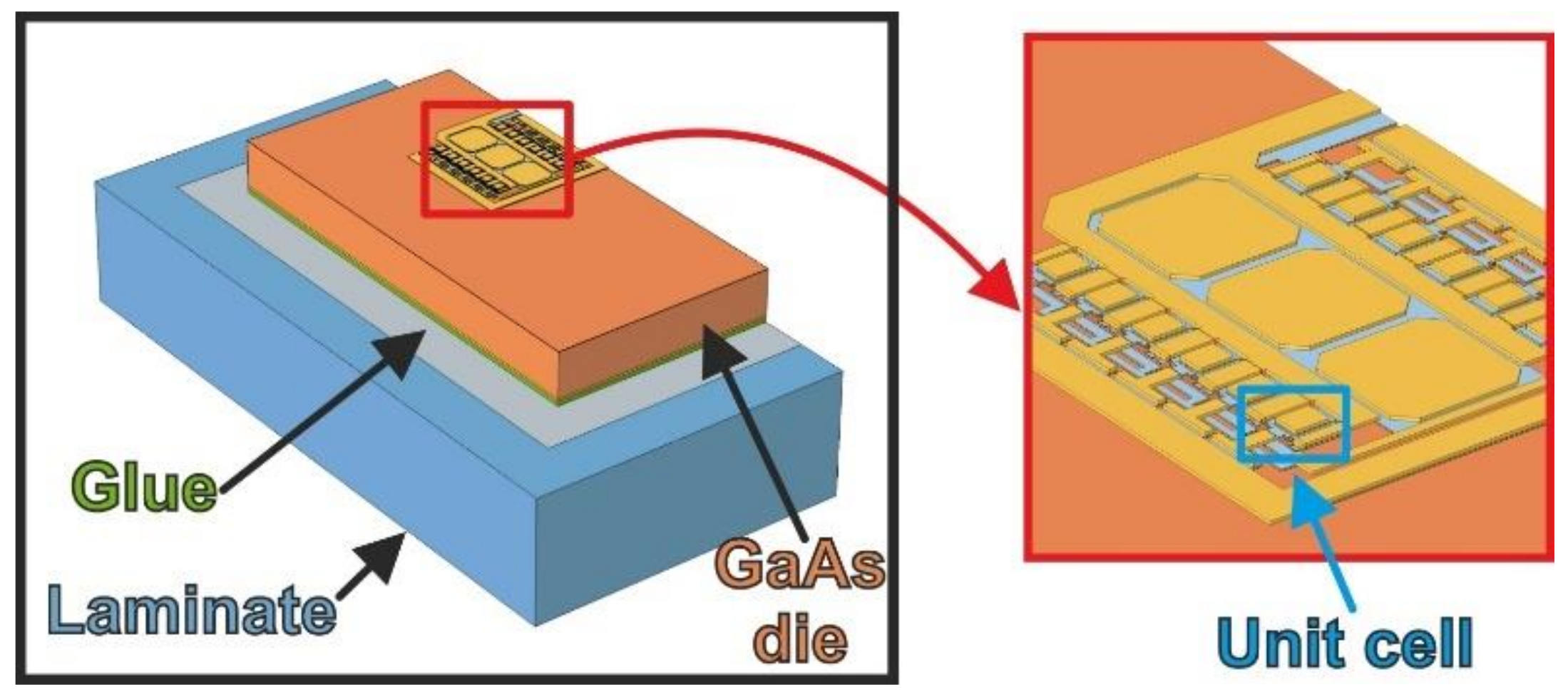
- Differently from [15], where the arrays were assumed to lie on an unthinned GaAs substrate (as typical for known-good-die identification), here they are considered in a realistic phone-board environment, i.e., the substrate is thinned and attached on a laminate, the bottom of which is at TB = 358 K.
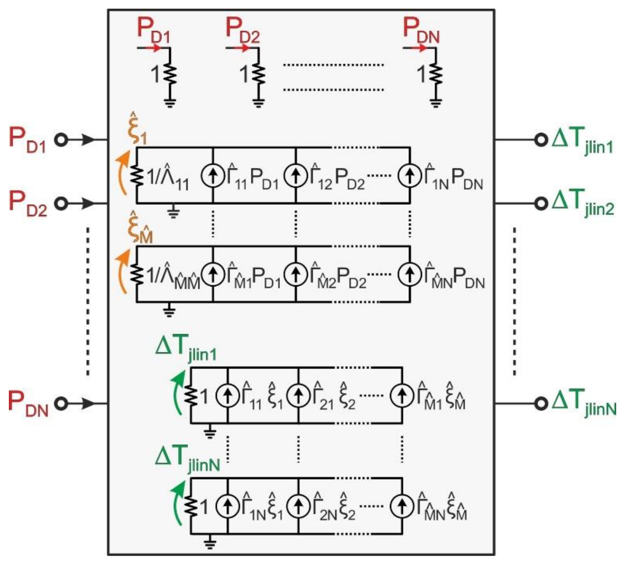
- Similar to [21], in this work the linear power-temperature feedback is described by invoking FANTASTIC [22,23], which is fed with the COMSOL geometry/mesh accompanied with additional information (on position/shape of heat sources, boundary conditions, and thermal conductivities), and rapidly extracts an ETN based on the RTH matrix without performing simulations. Contrary to conventional ETNs (like the one used in [15]), the FANTASTIC network allows reconstructing the overall temperature field for selected bias conditions in a post-processing step.
- In [15], the Kirchhoff’s transformation was applied by assuming that all materials share the same nonlinear thermal behavior as GaAs. Unfortunately, this was found to lead to a perceptible overestimation of ET effects. Here, more realistic results are achieved by carrying out a suitable preliminary calibration procedure, similar to that made in [21].
2. Devices and Arrays
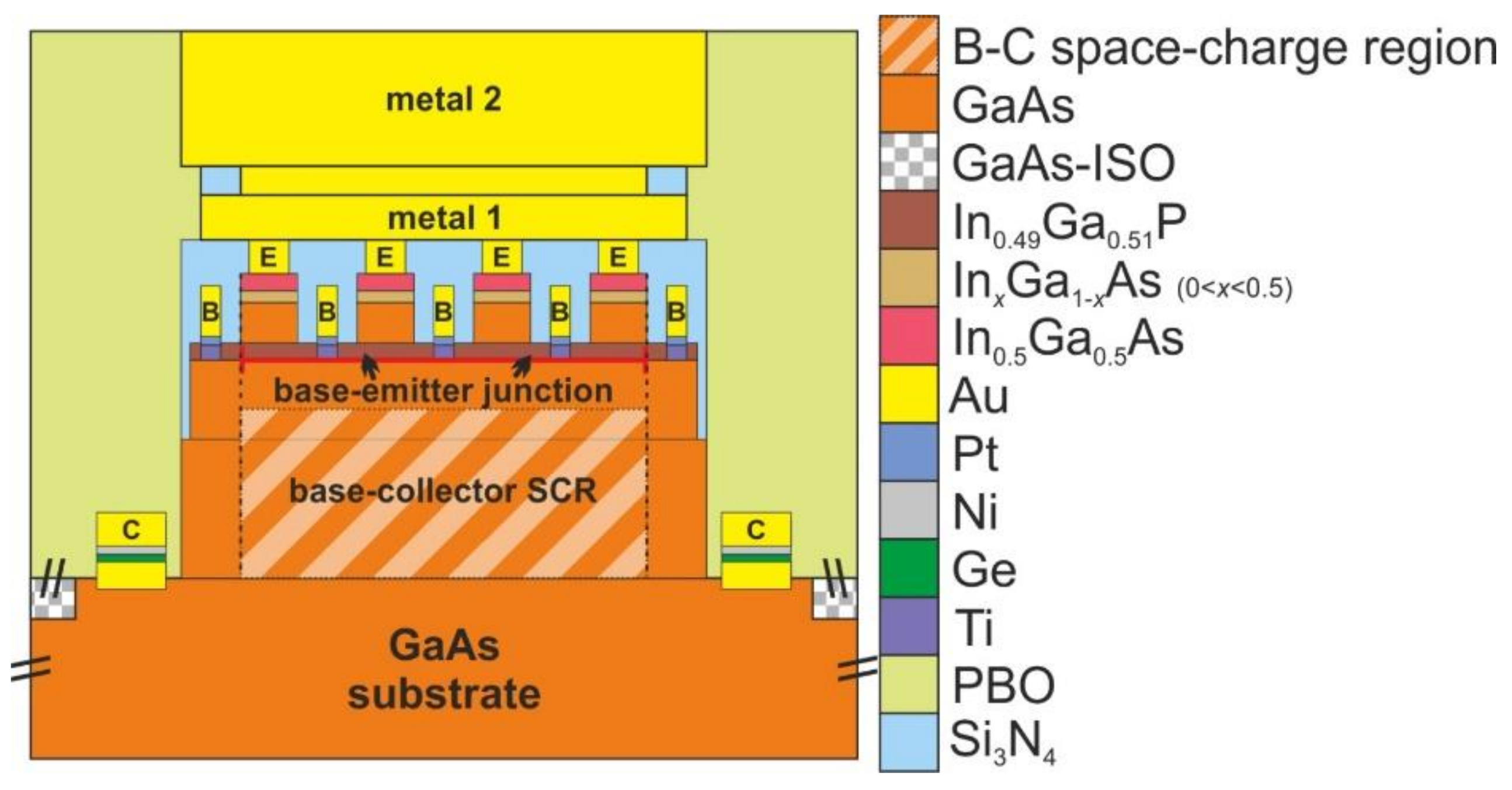
- an In0.5Ga0.5As cap to reduce the contact resistance with the gold (Au)-based emitter metallization;
- a grading InxGa1-xAs layer (with x spanning from 0.5 to 0) used to ensure a good lattice continuity with the underneath layer;
- a GaAs layer acting as a set-back for an easier manufacturing process;
- an n-doped In0.49Ga0.51P emitter layer, the bottom surface of which corresponds to the metallurgical base-emitter junction.
3. Simulation Approach
3.1. General Description
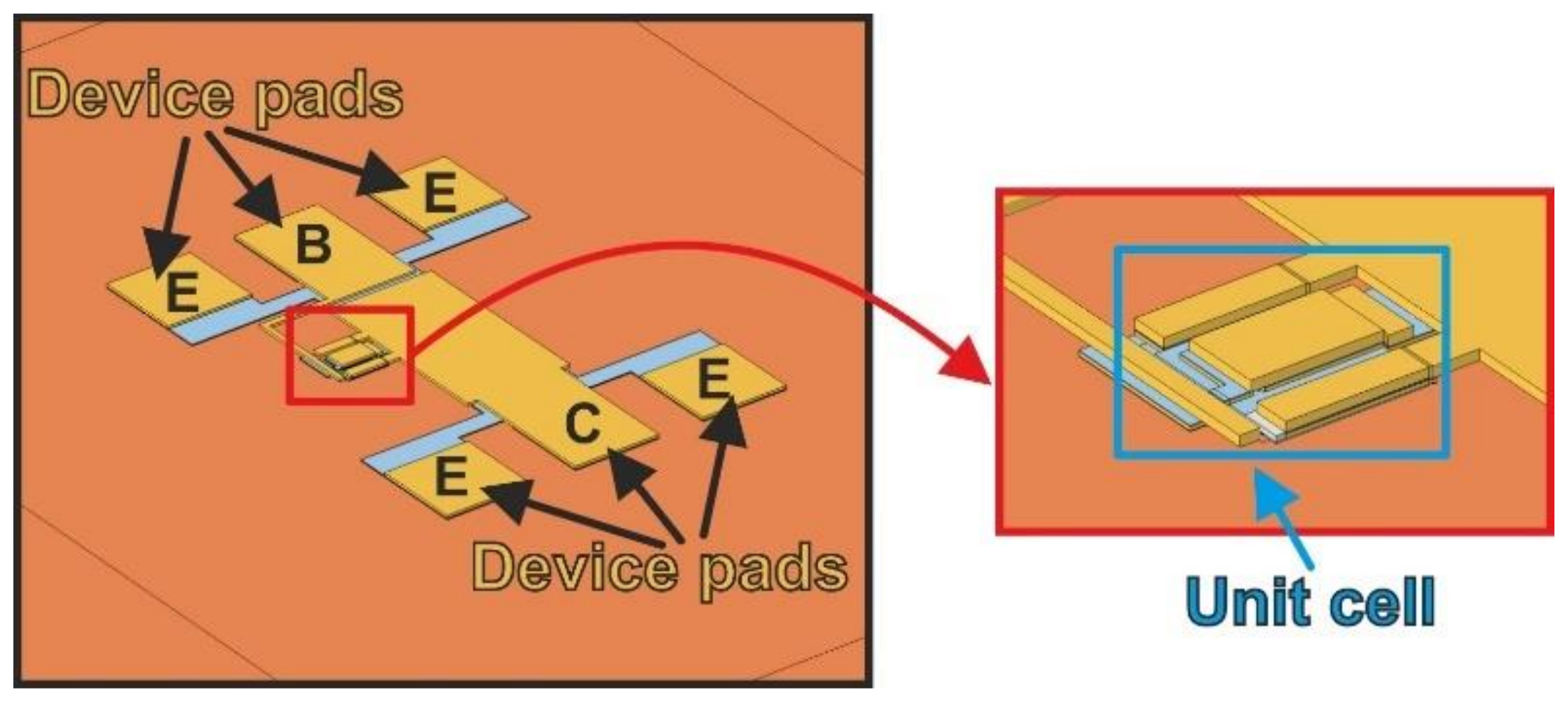
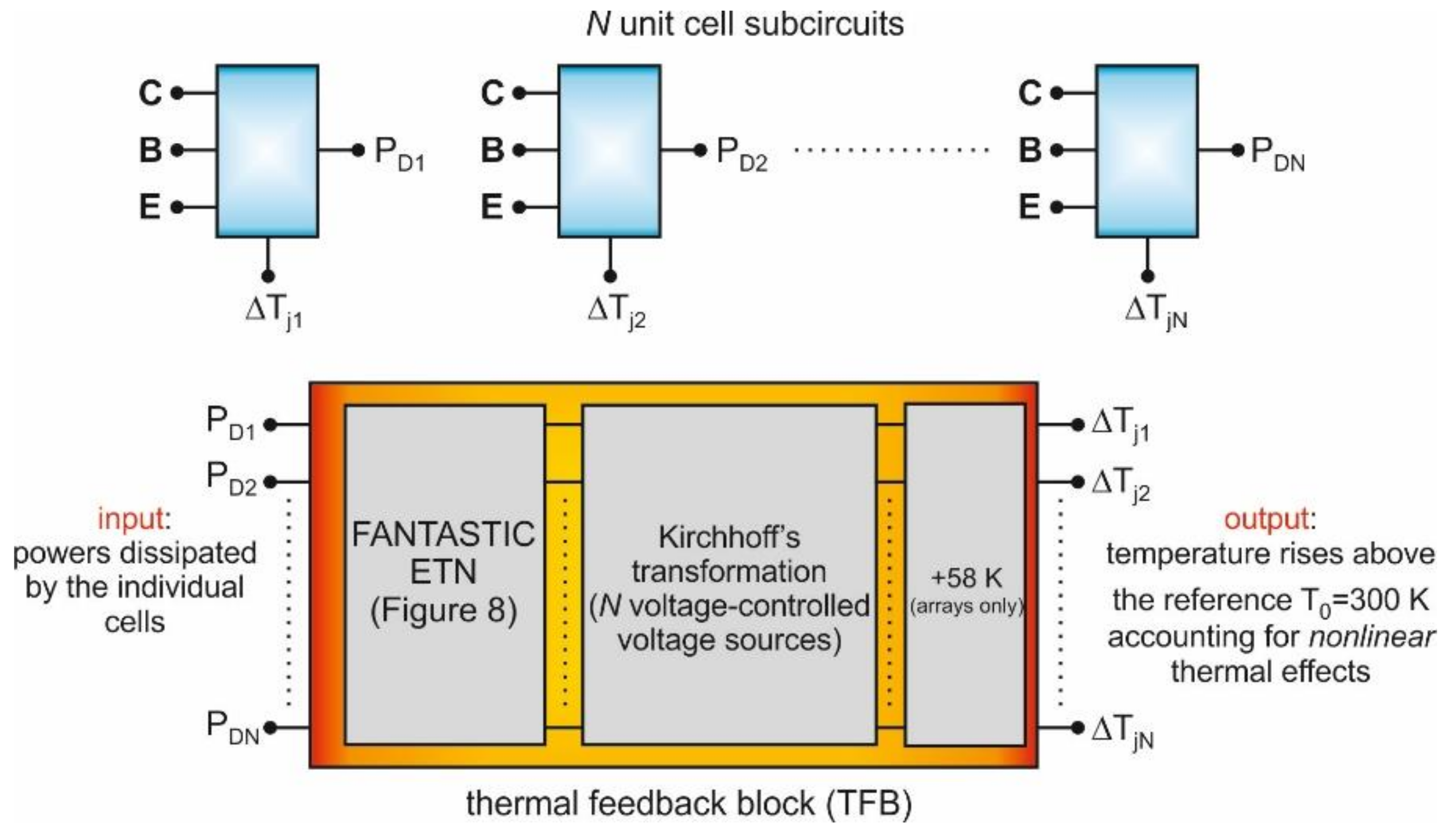
- Each four-finger unit cell is represented with one SPICE-compatible subcircuit (Section 3.3) implementing a simple analytical transistor model (Section 3.2). This assumption relies on the following considerations: (i) the two metals uniformly distribute the temperature over the base-emitter junction; (ii) the electron currents emerging from the four closely-spaced individual emitters are expected to spread and give rise to only one heat source. The subcircuit uses (i) a basic/standard bipolar transistor at reference (and unchangeable) temperature T0 as a core component, and (ii) linear and nonlinear controlled sources to account for the variation of the temperature-sensitive parameters during the simulation run, as well as for other specific mechanisms. According to the TEOL, the temperature rise ΔTj = Tj − T0 averaged over the base-emitter junction (which mainly influences the ET device behavior) is actually a voltage, while the dissipated power PD is treated as a current. In addition to the standard transistor terminals (emitter, base, and collector), the unit-cell subcircuit is also equipped with an input node carrying the “voltage” ΔTj and with an output node offering the “current” PD.
- The power-temperature feedback is described with a SPICE-compatible thermal feedback block (TFB), the construction of which is carried out in a pre-processing stage. The TFB contains an ETN including the matrix of self-heating (SH) RTHs of the unit cells and mutual RTHs among them. The inputs of the ETN are the powers PD dissipated by the cells (represented with currents), and the outputs are their temperature rises ΔTjlin = Tjlin − T0 for the test devices or ΔTjlinB = Tjlin − TB for the arrays (all emulated with voltages) under linear thermal conditions.
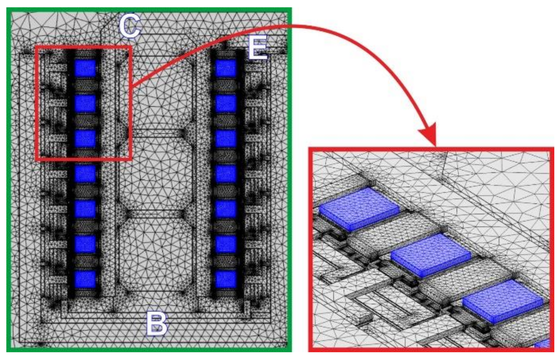
- The ETN is automatically determined through the following procedure. First, an accurate 3-D geometry/mesh of the domain is built in the COMSOL environment using an in-house routine; then, the geometry/mesh, along with additional information concerning position/shape of heat sources, boundary conditions, and thermal conductivities, is fed to FANTASTIC, which extracts the ETN in a really short time without the need of user’s intervention/expertise or onerous FEM simulations (Section 3.5). Generally, the whole process is very fast and error-free. The adoption of FANTASTIC is an improvement over our prior contribution [15], where (i) the RTH matrix was calculated by performing N purely-thermal static COMSOL simulations by activating only one heat source at a time, and (ii) the simple ETN adopted did not allow a post-processing reconstruction of the whole temperature map in the domain.
- As mentioned above, the ETN only accounts for linear thermal conditions. However, nonlinear thermal effects can be significant when particularly high temperatures are reached. Such effects are taken into account by making use of the Kirchhoff’s transformation, which converts the linear temperature rises ΔTjlin (test devices) or ΔTjlinB (arrays) offered by the ETN into the nonlinear counterparts ΔTj = Tj − T0 and ΔTjB = Tj − TB, respectively. Contrary to [15], here the transformation was properly calibrated (Section 3.4) to improve the ET simulation accuracy.
- Besides the ETN, the TFB also includes N voltage-controlled voltage sources that apply the calibrated Kirchhoff’s transformation to the ETN linear outcomes; as a result, the nonlinear temperature rises ΔTj (test devices) and ΔTjB (arrays) are computed; only for the arrays, the increment TB − T0 is added to ΔTjB to get the N nonlinear ΔTj = Tj − T0 to be provided to the unit-cell subcircuits.
- The subcircuits are then connected to the TFB in the environment of a commercial circuit simulation tool. As a result, the whole domain is transformed into a purely-electrical macrocircuit, which inherently accounts for ET effects (Section 3.6): the temperature, and thus the temperature-sensitive parameters, are allowed to vary during the simulation run. The task of solving this macrocircuit is given to the powerful and robust engine of the circuit simulation tool, with very low computational effort and minimized occurrence of convergence issues compared to other numerical methods.
3.2. Bipolar Transistor Model
- ICnoAV [A] is the collector current in the absence of impact-ionization (II), or avalanche, effects;
- IAV [A] is the collector current component only induced by avalanche;
- VCB [V] is the collector-base voltage;
- VAF [V] is the forward Early voltage;
- M (≥ 1) is the dimensionless VCB-dependent avalanche multiplication factor;
- AE [µm2] is the emitter area;
- JS0 [A/µm2] is the reverse saturation current density at the reference temperature T0 = 300 K;
- η is the ideality coefficient at T0;
- VT0 = 0.02586 V is the thermal voltage at T0;
- VBEj [V] is the internal (junction) base-emitter voltage, that is, VBEj = VBE − RB·IB − RE·IE, where VBE is the externally-accessible base-emitter voltage, IB, IE [A] are the base and emitter currents, and RB, RE [Ω] are the parasitic base and emitter resistances, respectively;
- the temperature rise ΔTj [K] is defined as Tj − T0, Tj being the temperature averaged over the base-emitter junction;
- ϕ [V/K] is the temperature coefficient of VBEj;
- BHI (≥1) is an IE-dependent dimensionless term introduced to describe the attenuation dictated by high-injection (HI) effects, i.e., the Kirk-induced gain roll-off.
3.3. SPICE Unit-Cell Subcircuit
3.4. Construction of the Geometry/Mesh in COMSOL and Calibration of the Kirchhoff’s Transformation
3.5. FANTASTIC
| Algorithm 1: SCTM extraction |
| Set V:=0 |
| for each heat source n=1, …, N do |
| 1 Solve (21) for Θn |
| 2 Update matrix V by appending Θn |
| 3 Generate a SCTM projecting (12)–(14) onto V |
3.6. Construction of the Macrocircuit
3.7. Extension to the Dynamic Case
- The selected transistor model must be provided with a power (output) node, and the internal one- or two-pair thermal network has to be deactivated.
- All parameters of the model must be extracted from experimental data, which is a nontrivial task.
- As mentioned in Section 3.5, if FANTASTIC is also fed with the mass density and specific heat for all materials, it can be enabled to extract a DCTM of the domain and the associated ETN accounting for the dynamic heat propagation [21,22,23]. Such an ETN, together with the Kirchhoff’s transformation sources, will constitute the SPICE- and ADS-compatible TFB.
- Lastly, the macrocircuit has to be built in ADS by connecting the model instances among them and with the TFB.
4. Results and Discussion
4.1. Test Devices
4.2. Transistor Arrays
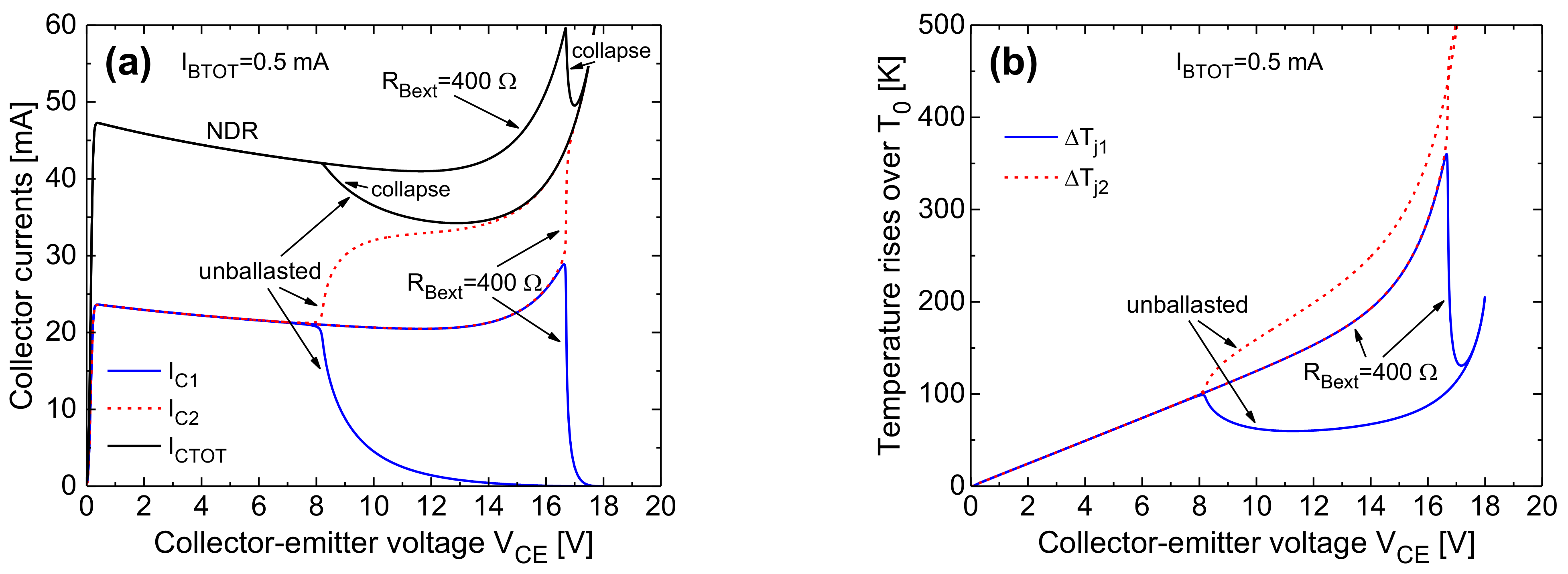
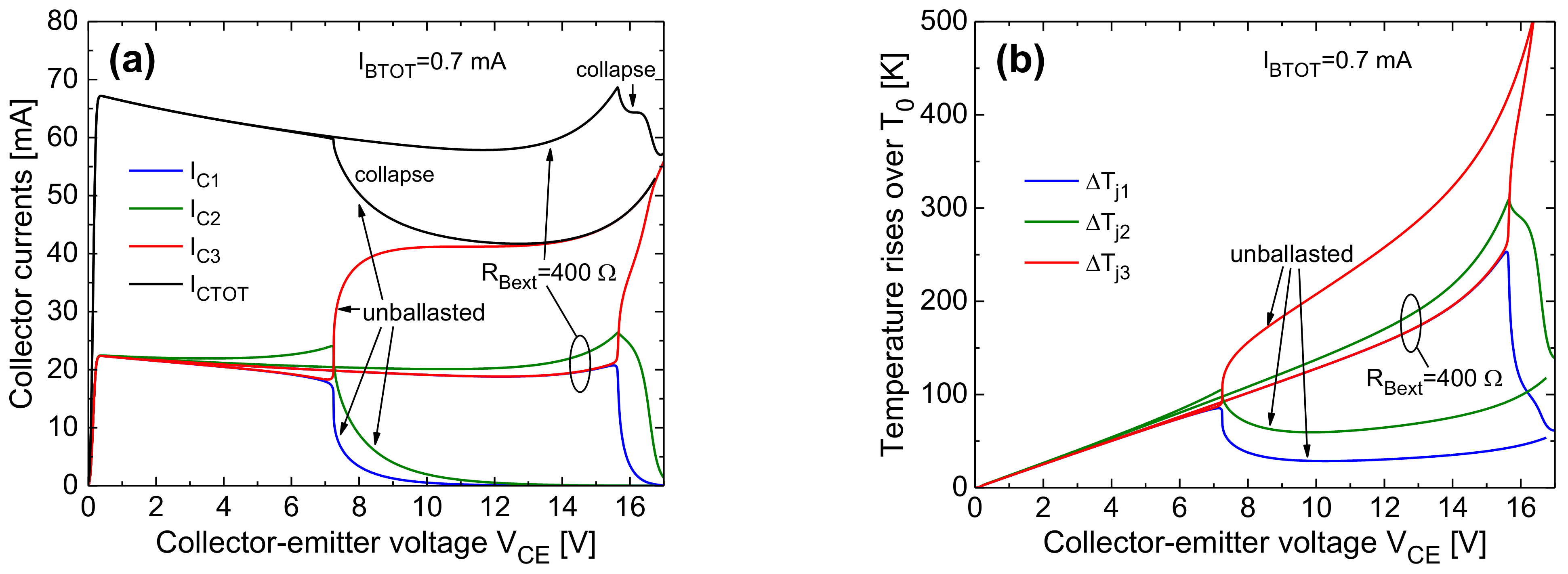
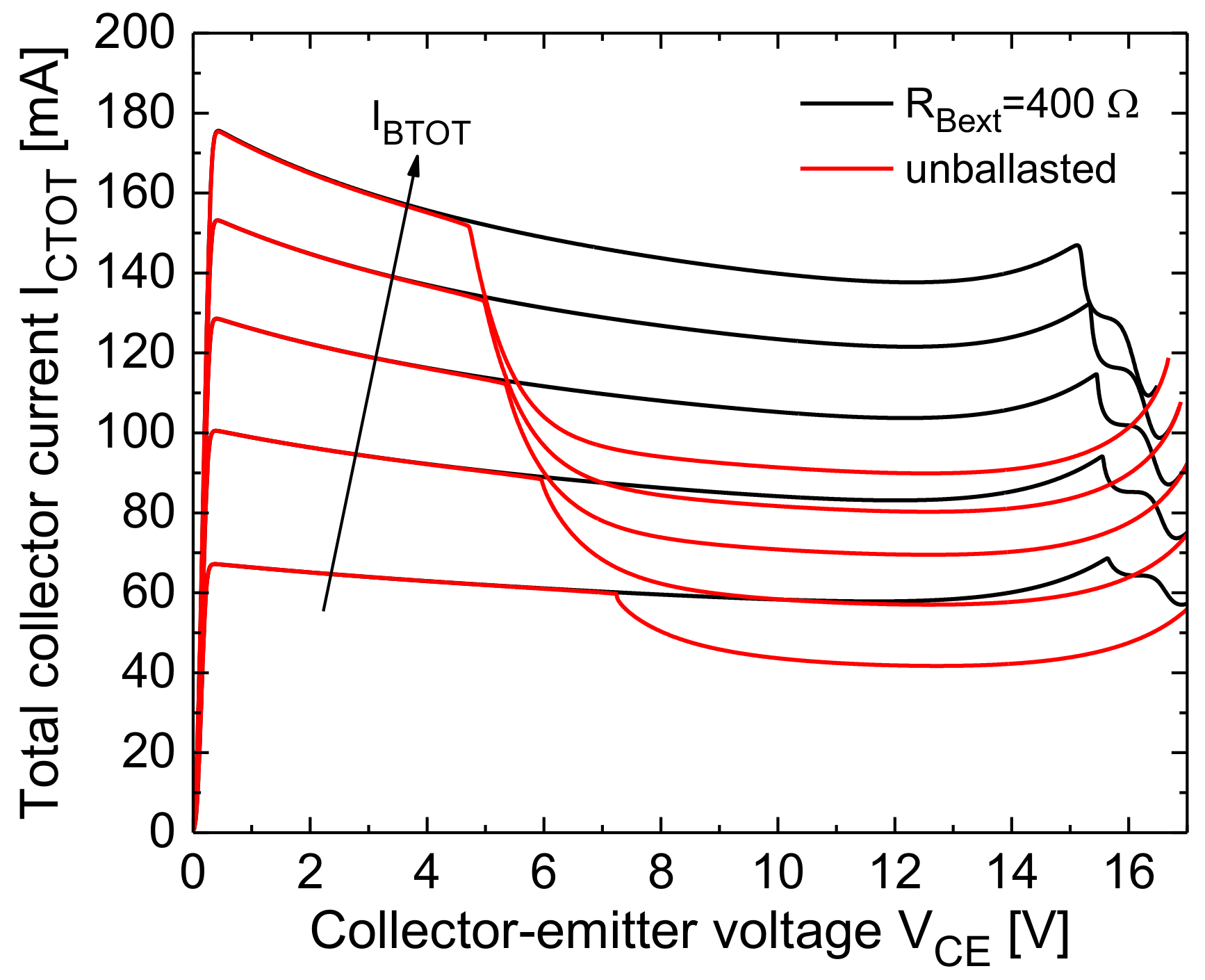
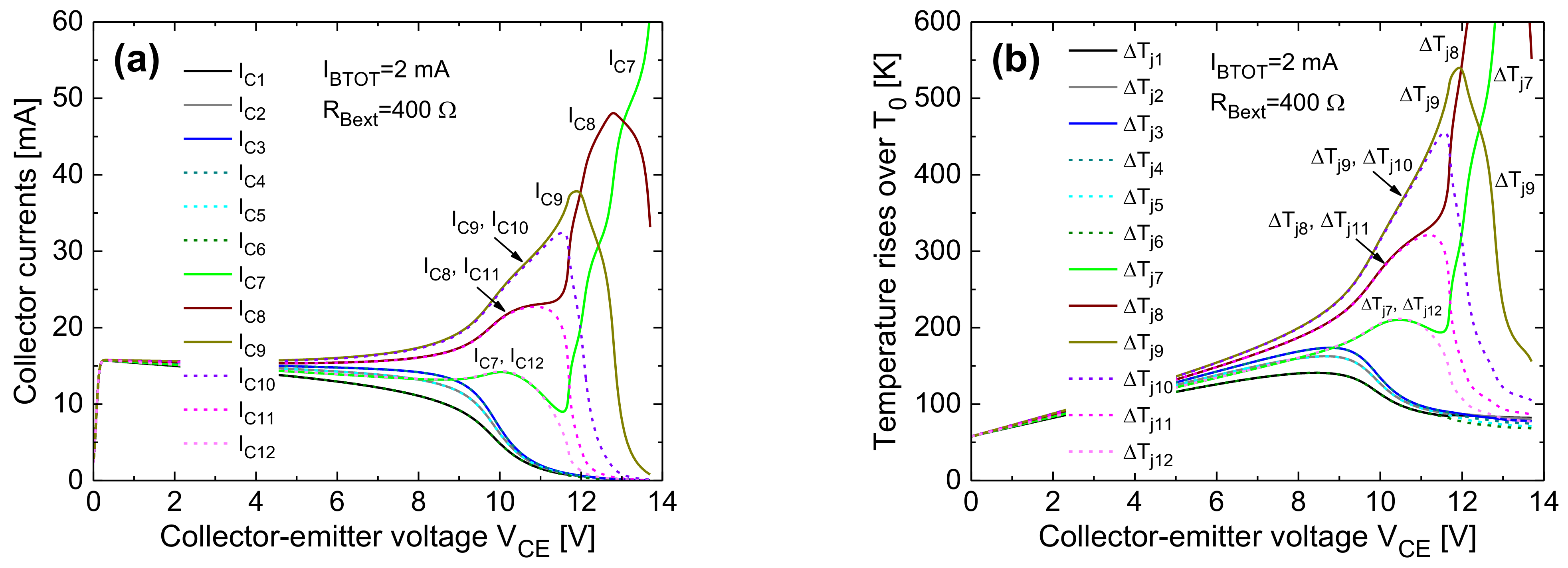
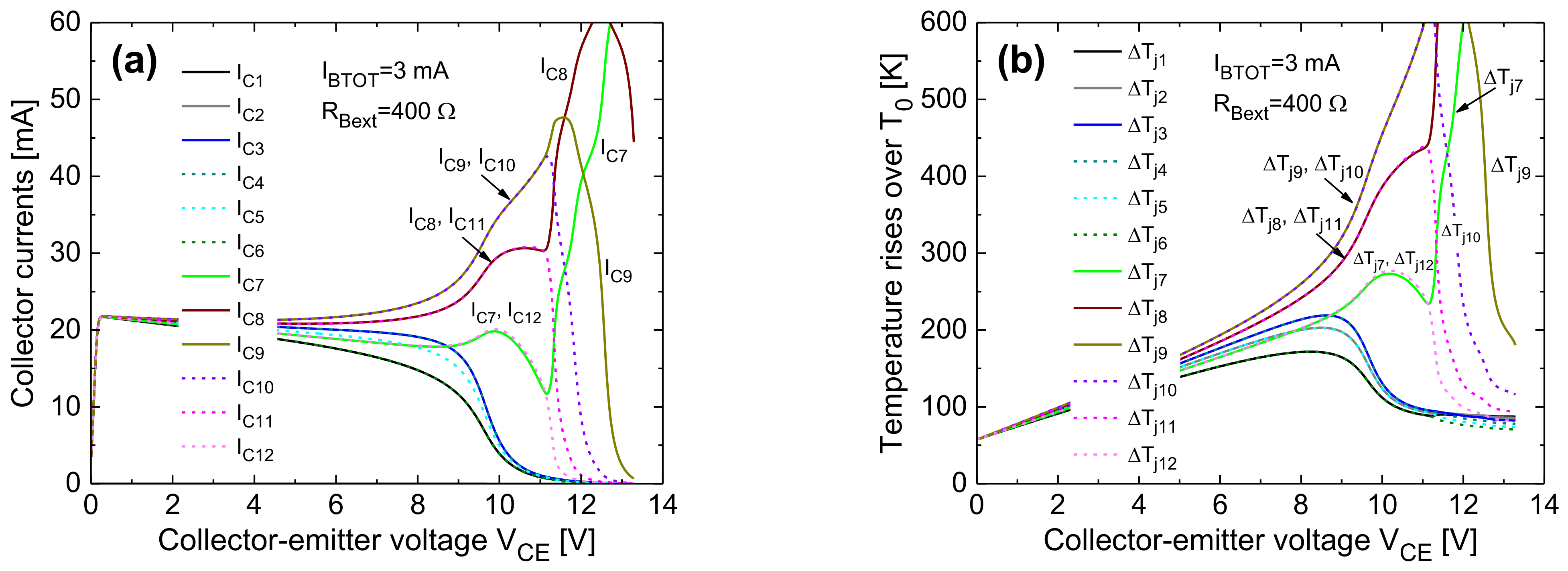
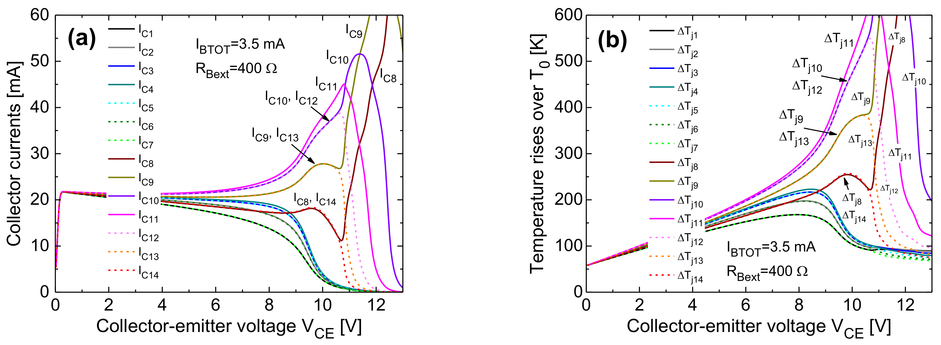
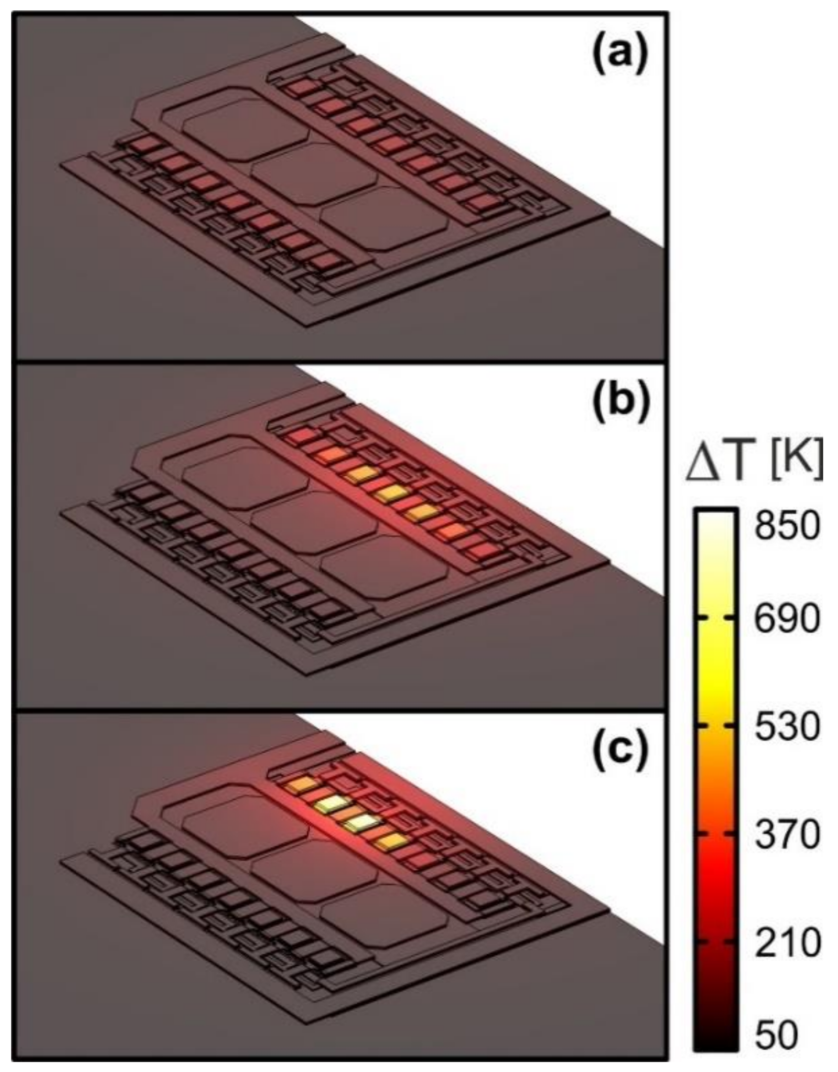
- The collapse onset in an IBTOT-constant ICTOT–VCE curve is associated to a uneven current/temperature distribution, wherein the right-column cells (in particular, the inner ones) bear almost all the current.
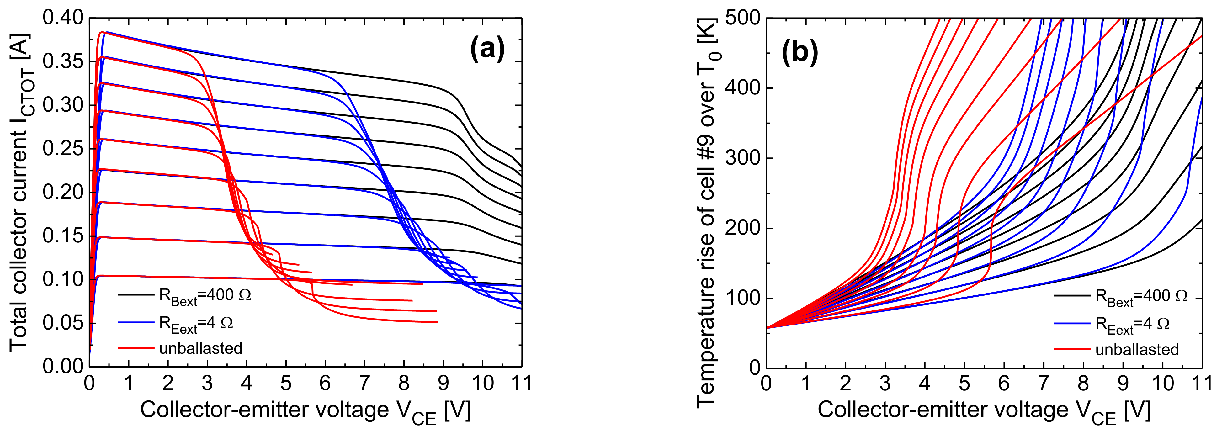
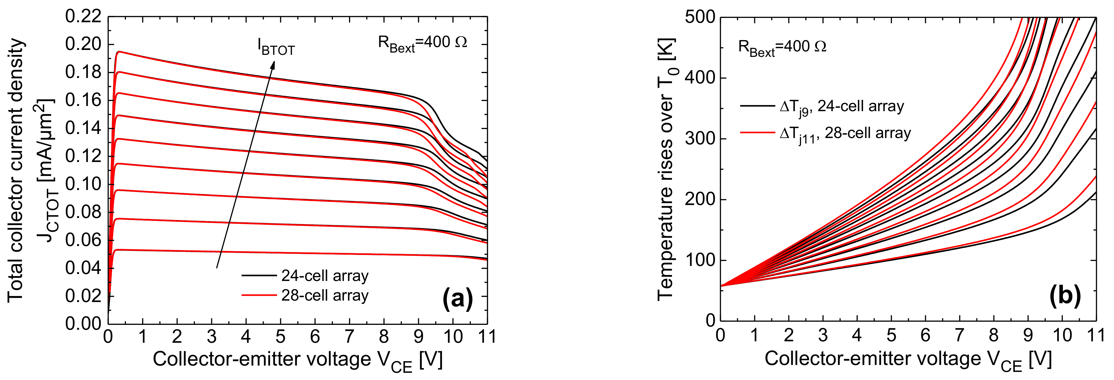
- The steeper ICTOT drop in the collapse region is induced by a bifurcation mechanism involving the symmetric cells belonging to the right column. In the base-ballasted case (with RBext = 400 Ω) this leads to three adjacent cells conducting all the current (either the top or the bottom ones, depending on small technological/layout discrepancies); a further VCE increase makes the current flow in two cells, and eventually in only one cell (the outer one). In the unballasted and emitter-ballasted case (with REext = 4 Ω), for VCE slightly higher than that entailing the bifurcation, the current flows in only one of the inner cells (#9 or #10). This leads to a very sharp and linear temperature increment vs. VCE of this cell (plainly illustrated for cell #9 in Figure 23b).
- Such a linear nature of the ΔTj9–VCE behavior can be straightforwardly explained as follows. Neglecting II effects, which is reasonable in both the unballasted and emitter-ballasted cases, ΔTj9 is approximately equal to RTH99(Tj9)·βF(Tj9)·IBTOT·VCE + 58 K (IB9 ≈ IBTOT), where RTH99 is the SH thermal resistance of cell #9, and 58 K is the difference between TB and T0; as VCE increases, there is a compensation between the NTC of βF and the increase in RTH99 with temperature due to nonlinear thermal effects.
5. Conclusions
Author Contributions
Funding
Data Availability Statement
Acknowledgments
Conflicts of Interest
Nomenclature
| CB | common base |
| CE | common emitter |
| DCTM | dynamic compact thermal model |
| DoF | degree of freedom |
| ET | electrothermal |
| ETN | equivalent thermal network |
| FANTASTIC | FAst Novel Thermal Analysis Simulation Tool for Integrated Circuits |
| FEM | finite-element method |
| GaAs | gallium arsenide |
| HBT | heterojunction bipolar transistor |
| HI | high injection |
| II | impact ionization (avalanche) |
| MOR | model-order reduction |
| NDR | negative differential resistance |
| NTC | negative temperature coefficient |
| PA | power amplifier |
| PTC | positive temperature coefficient |
| RTH | thermal resistance [K/W] |
| SCR | space-charge region |
| SCTM | static compact thermal model |
| SH | self-heating |
| SOG | silicon-on-glass |
| TEOL | thermal equivalent of the Ohm’s law |
| TFB | thermal feedback block |
| T0 | reference temperature: 300 K |
| TB | temperature of the laminate bottom for the arrays: 358 K |
| Tj | temperature averaged over the base-emitter junction under nonlinear thermal conditions |
| Tjlin | temperature averaged over the base-emitter junction under linear thermal conditions |
| ΔTj | temperature rise Tj-T0 |
| ΔTjlin | temperature rise Tjlin-T0 |
| ΔTjB | temperature rise Tj-TB |
| ΔTjlinB | temperature rise Tjlin-TB |
References
- Fresina, M. Trends in GaAs HBTs for wireless and RF. In Proceedings of the IEEE Bipolar/BiCMOS Circuits and Technology Meeting (BCTM), Atlanta, GA, USA, 9–11 October 2011; pp. 150–153. [Google Scholar]
- Zarębski, J.; Górecki, K. SPICE-aided modelling of dc characteristics of power bipolar transistors with self-heating taken into account. Int. J. Numer. Model. 2009, 22, 422–433. [Google Scholar] [CrossRef]
- Zarębski, J.; Górecki, K. The electrothermal large-signal model of power MOS transistors for SPICE. IEEE Trans. Power Electron. 2010, 25, 1265–1274. [Google Scholar] [CrossRef]
- Górecki, K.; Górecki, P. Modelling dynamic characteristics of the IGBT with thermal phenomena taken into account. Microelectron. Int. 2017, 34, 160–164. [Google Scholar] [CrossRef]
- Nenadović, N.; d’Alessandro, V.; La Spina, L.; Rinaldi, N.; Nanver, L.K. Restabilizing mechanisms after the onset of thermal instability in bipolar transistors. IEEE Trans. Electron Devices 2006, 53, 643–653. [Google Scholar] [CrossRef]
- La Spina, L.; d’Alessandro, V.; Russo, S.; Rinaldi, N.; Nanver, L.K. Influence of concurrent electrothermal and avalanche effects on the safe operating area of multifinger bipolar transistors. IEEE Trans. Electron Devices 2009, 56, 483–491. [Google Scholar] [CrossRef]
- La Spina, L.; d’Alessandro, V.; Russo, S.; Nanver, L.K. Thermal design of multifinger bipolar transistors. IEEE Trans. Electron Devices 2010, 57, 1789–1800. [Google Scholar] [CrossRef]
- Metzger, A.G.; d’Alessandro, V.; Rinaldi, N.; Zampardi, P.J. Evaluation of thermal balancing techniques in InGaP/GaAs HBT power arrays for wireless handset power amplifiers. Microelectron. Reliab. 2013, 53, 1471–1475. [Google Scholar] [CrossRef]
- Rinaldi, N.; d’Alessandro, V. Analysis of the bipolar current mirror including electrothermal and avalanche effects. IEEE Trans. Electron Devices 2009, 56, 1309–1321. [Google Scholar] [CrossRef]
- D’Alessandro, V.; de Magistris, M.; Magnani, A.; Rinaldi, N.; Grivet-Talocia, S.; Russo, S. Time domain dynamic electrothermal macromodeling for thermally aware integrated system design. In Proceedings of the IEEE workshop on Signal and Power Integrity (SPI), Paris, France, 12–15 May 2013. [Google Scholar]
- D’Alessandro, V.; La Spina, L.; Nanver, L.K.; Rinaldi, N. Analysis of electrothermal effects in bipolar differential pairs. IEEE Trans. Electron Dev. 2011, 58, 966–978. [Google Scholar] [CrossRef]
- D’Alessandro, V.; de Magistris, M.; Magnani, A.; Rinaldi, N.; Russo, S. Dynamic electrothermal analysis of bipolar devices and circuits relying on multi-port positive Foster representation. In Proceedings of the IEEE Bipolar/BiCMOS Circuits and Technology Meeting (BCTM), Portland, OR, USA, 30 September–3 October 2012. [Google Scholar]
- D’Alessandro, V.; D’Esposito, R.; Metzger, A.G.; Kwok, K.H.; Aufinger, K.; Zimmer, T.; Rinaldi, N. Analysis of electrothermal and impact-ionization effects in bipolar cascode amplifiers. IEEE Trans. Electron Devices 2018, 65, 431–439. [Google Scholar] [CrossRef]
- D’Alessandro, V.; Magnani, A.; Riccio, M.; Breglio, G.; Irace, A.; Rinaldi, N.; Castellazzi, A. SPICE modeling and dynamic electrothermal simulation of SiC power MOSFETs. In Proceedings of the IEEE International Symposium on Power Semiconductor Devices and ICs (ISPSD), Waikoloa, HI, USA, 15–19 June 2014; pp. 285–288. [Google Scholar]
- D’Alessandro, V.; Catalano, A.P.; Codecasa, L.; Moser, B.; Zampardi, P.J. Combined SPICE-FEM analysis of electrothermal effects in InGaP/GaAs HBT devices and arrays for handset applications. In Proceedings of the IEEE International Conference on Thermal, Mechanical and Multi-Physics Simulation and Experiments in Microelectronics and Microsystems (EuroSimE), Toulouse, France, 15–18 April 2018. [Google Scholar]
- COMSOL Multiphysics User’s Guide, Release 5.2A. 2016. Available online: https://www.comsol.it/ (accessed on 1 October 2020).
- D’Alessandro, V.; Catalano, A.P.; Codecasa, L.; Zampardi, P.J.; Moser, B. Accurate and efficient analysis of the upward heat flow in InGaP/GaAs HBTs through an automated FEM-based tool and Design of Experiments. Int. J. Numer. Model. Electron. Netw. Devices Fields 2019, 32, e2530. [Google Scholar] [CrossRef]
- Carlslaw, H.S.; Jaeger, J.C. Conduction of Heat in Solids, 2nd ed.; Oxford University Press: London, UK, 1959. [Google Scholar]
- Joyce, W.B. Thermal resistance of heat sinks with temperature-dependent conductivity. Solid State Electron. 1975, 18, 321–322. [Google Scholar] [CrossRef]
- PSPICE User’s Manual, Cadence OrCAD 16.5. 2011. Available online: https://www.orcad.com/ (accessed on 1 October 2020).
- D’Alessandro, V.; Codecasa, L.; Catalano, A.P.; Scognamillo, C. Circuit-based electrothermal simulation of multicellular SiC power MOSFETs using FANTASTIC. Energies 2020, 13, 4563. [Google Scholar] [CrossRef]
- Codecasa, L.; d’Alessandro, V.; Magnani, A.; Rinaldi, N.; Zampardi, P.J. FAst novel thermal analysis simulation tool for integrated circuits (FANTASTIC). In Proceedings of the International workshop on THERMal INvestigations of ICs and systems (THERMINIC), London, UK, 24–26 September 2014. [Google Scholar]
- Magnani, A.; d’Alessandro, V.; Codecasa, L.; Zampardi, P.J.; Moser, B.; Rinaldi, N. Analysis of the influence of layout and technology parameters on the thermal impedance of GaAs HBT/BiFET using a highly-efficient tool. In Proceedings of the IEEE Compound Semiconductor Integrated Circuit Symposium (CSICS), La Jolla, CA, USA, 19–22 October 2014. [Google Scholar]
- D’Alessandro, V.; Catalano, A.P.; Magnani, A.; Codecasa, L.; Rinaldi, N.; Moser, B.; Zampardi, P.J. Simulation comparison of InGaP/GaAs HBT thermal performance in wire-bonding and flip-chip technologies. Microelectron. Reliab. 2017, 78, 233–242. [Google Scholar] [CrossRef]
- Zhang, Q.M.; Hu, H.; Sitch, J.; Surridge, R.K.; Xu, J.M. A new large signal HBT model. IEEE Trans. Microw. Theory Tech. 1996, 44, 2001–2009. [Google Scholar] [CrossRef]
- Liu, W.; Khatibzadeh, A. The collapse of current gain in multi-finger heterojunction bipolar transistors: Its substrate temperature dependence, instability criteria, and modeling. IEEE Trans. Electron. Devices 1994, 41, 1698–1707. [Google Scholar] [CrossRef]
- Nenadović, N.; d’Alessandro, V.; Nanver, L.K.; Tamigi, F.; Rinaldi, N.; Slotboom, J.W. A back-wafer contacted silicon-on-glass integrated bipolar process–Part II: A novel analysis of thermal breakdown. IEEE Trans. Electron. Devices 2004, 51, 51–62. [Google Scholar] [CrossRef]
- D’Alessandro, V.; Marano, I.; Russo, S.; Céli, D.; Chantre, A.; Chevalier, P.; Pourchon, F.; Rinaldi, N. Impact of layout and technology parameters on the thermal resistance of SiGe:C HBTs. In Proceedings of the IEEE Bipolar/BiCMOS Circuits and Technology Meeting (BCTM), Austin, TX, USA, 4–6 October 2010; pp. 137–140. [Google Scholar]
- D’Alessandro, V.; Sasso, G.; Rinaldi, N.; Aufinger, K. Influence of scaling and emitter layout on the thermal behavior of toward-THz SiGe:C HBTs. IEEE Trans. Electron. Devices 2014, 61, 3386–3394. [Google Scholar] [CrossRef] [Green Version]
- Miller, S.L. Ionization rates for holes and electrons in silicon. Phys. Rev. 1957, 105, 1246–1249. [Google Scholar] [CrossRef]
- Rinaldi, N.; d’Alessandro, V. Theory of electrothermal behavior of bipolar transistors: Part III–Impact ionization. IEEE Trans. Electron Devices 2006, 53, 1683–1697. [Google Scholar] [CrossRef]
- Zampardi, P.J.; Yang, Y.; Hu, J.; Li, B.; Fredriksson, M.; Kwok, K.H.; Shao, H. Practical statistical simulation for efficient circuit design. In Nonlinear Transistor Model Parameter Extraction Techniques; Chapter 9; Rudolph, M., Fager, C., Root, D.E., Eds.; Cambridge University Press: Cambridge, UK, 2011; pp. 287–317. [Google Scholar]
- Palankovski, V.; Quay, R. Analysis and Simulation of Heterostructure Devices; Springer: New York, NY, USA, 2004. [Google Scholar]
- Anholt, R. HBT thermal element design using an electro/thermal simulator. Solid State Electron. 1998, 42, 857–864. [Google Scholar] [CrossRef]
- Lienhard, J.H., IV; Lienhard, J.H., V. A Heat Transfer Textbook; Phlogiston Press: Cambridge, MA, USA, 2008. [Google Scholar]
- Poulton, K.; Knudsen, K.L.; Corcoran, J.J.; Wang, K.-C.; Pierson, R.L.; Nubling, R.B.; Chang, M.-C.F. Thermal design and simulation of bipolar integrated circuits. IEEE J. Solid State Circuits 1992, 27, 1379–1387. [Google Scholar] [CrossRef]
- Codecasa, L.; D’Amore, D.; Maffezzoni, P. Compact modeling of electrical devices for electrothermal analysis. IEEE Trans. Circuits Syst. I 2003, 50, 465–476. [Google Scholar] [CrossRef]
- Codecasa, L.; Catalano, A.P.; d’Alessandro, V. A priori error bound for moment matching approximants of thermal models. IEEE Trans. Comp. Packag. Manufact. Technol. 2019, 9, 2383–2392. [Google Scholar] [CrossRef]
- Keysight Advanced Design System (ADS). 2019. Available online: https://edadocs.software.keysight.com/ads2019 (accessed on 25 January 2021).
- Schröter, M.; Chakravorty, A. Compact Hierarchical Bipolar Transistor Modeling with HICUM; World Scientific Publishing: Singapore, 2010. [Google Scholar]
- Keysight ADS Electro-Thermal Simulator (Agilent EEsof EDA). Available online: https://www.keysight.com/upload/cmc_upload/All/ADSElectrothermal.pdf (accessed on 25 January 2021).
- Dawson, D.E.; Gupta, A.K.; Salib, M.L. CW measurements of HBT thermal resistance. IEEE Trans. Electron Devices 1992, 39, 2235–2239. [Google Scholar] [CrossRef]
- Popescu, C. Selfheating and thermal runaway phenomena in semiconductor devices. Solid State Electron. 1970, 13, 441–450. [Google Scholar] [CrossRef]
- Latif, M.; Bryant, P.R. Multiple equilibrium points and their significance in the second breakdown of bipolar transistors. IEEE J. Solid State Circuits 1981, 16, 8–15. [Google Scholar] [CrossRef]
- Rinaldi, N.; d’Alessandro, V. Theory of electrothermal behavior of bipolar transistors: Part I–Single-finger devices. IEEE Trans. Electron Devices 2005, 52, 2009–2021. [Google Scholar] [CrossRef]
- Jaoul, M.; Céli, D.; Maneux, C.; Zimmer, T. Measurement based accurate definition of the SOA edges for SiGe HBTs. In Proceedings of the IEEE BiCMOS and Compound semiconductor Integrated Circuits and Technology Symposium (BCICTS), Nashville, TN, USA, 3–6 November 2019. [Google Scholar]
- Liu, W.; Khatibzadeh, A.; Sweder, J.; Chau, H.-F. The use of base ballasting to prevent the collapse of current gain in AlGaAs/GaAs heterojunction bipolar transistors. IEEE Trans. Electron Devices 1996, 43, 245–251. [Google Scholar] [CrossRef]
- Vanhoucke, T.; Hurkx, G.A.M. Unified electro-thermal stability criterion for bipolar transistors. In Proceedings of the IEEE Bipolar/BiCMOS Circuits and Technology Meeting (BCTM), Santa Barbara, CA, USA, 9–11 October 2005; pp. 37–40. [Google Scholar]
- Seiler, U.; Koenig, E.; Narozny, P.; Dämbkes, H. Thermally triggered collapse of collector current in power heterojunction bipolar transistors. In Proceedings of the IEEE Bipolar/BiCMOS Circuits and Technology Meeting (BCTM), Minneapolis, MN, USA, 4–5 October 1993; pp. 257–260. [Google Scholar]
- Liu, W.; Nelson, S.; Hill, D.G.; Khatibzadeh, A. Current gain collapse in microwave multifinger heterojunction bipolar transistors operated at very high power densities. IEEE Trans. Electron Devices 1993, 40, 1917–1927. [Google Scholar] [CrossRef]
- Liu, W. Thermal coupling in 2-finger heterojunction bipolar transistors. IEEE Trans. Electron Devices 1995, 42, 1033–1038. [Google Scholar] [CrossRef]
- Wang, K.-C.; Asbeck, P.M.; Chang, M.-C.F.; Miller, D.L.; Sullivan, G.J.; Corcoran, J.J.; Hornak, T. Heating effects on the accuracy of HBT voltage comparators. IEEE Trans. Electron Devices 1987, 34, 1729–1735. [Google Scholar] [CrossRef]
- Järvinen, E.; Kalajo, S.; Matilainen, M. Bias circuits for GaAs HBT power amplifiers. In Proceedings of the IEEE MTT-S International Microwave Symposium Digest, Phoenix, AZ, USA, 20–24 May 2001; pp. 507–510. [Google Scholar]
- Zampardi, P.J. Silicon modelers are from Mars, GaAs modelers are from Venus. In Proceedings of the IEEE Bipolar/BiCMOS Circuits and Technology Meeting (BCTM), Miami, FL, USA, 19–21 October 2017; pp. 257–260. [Google Scholar]







| Parameter | Value |
|---|---|
| Common-emitter current gain at 300 K and medium current levels βF0 | 135 |
| Open-emitter breakdown voltage BVCBO | 27 V |
| Open-base breakdown voltage BVCEO | 17 V |
| Peak cut-off frequency fT for VCE = 3 V | 40 GHz |
| Collector current density JC at peak fT for VCE = 3 V | 0.2 mA/µm2 |
| Maximum oscillation frequency fMAX | 82 GHz |
| Parameter | Value |
|---|---|
| AE | 164 µm2 |
| JS0 | 3.5 × 10⁻²⁶ A/µm2 |
| η | 1.01 |
| VAF | 1000 V |
| βF0 | 135 |
| ϕ0 | 5.4 mV/K |
| ΔEG/k | 200 K−1 |
| JHI | 0.35 mA/µm2 |
| nHI | 1 |
| BVCBO | 27 V |
| nAV | 9 [32] |
| RE | 1 Ω |
| RB | 3.5 Ω |
| Material | k(T0) (W/µmK) | k(TB) (W/µmK) | Temperature Dependence |
|---|---|---|---|
| Si3N4 | 18.5 × 10⁻⁶ [33] | 19.6 × 10⁻⁶ | (8), α = −0.33 [33] |
| In0.5Ga0.5As | 0.048 × 10⁻⁴ [33] | 3.9 × 10⁻⁶ | (8), α = 1.175 [33] |
| InxGa1-xAs (0 < x< 0.5) | 0.092 × 10⁻⁴ [33] average in the layer | 7.4 × 10⁻⁶ | (8), α = 1.212 [33] |
| GaAs | 4.6 × 10⁻⁵ [33] | 3.69 × 10⁻⁵ | (8), α = 1.25 [33] |
| ion-implanted GaAs | 0.046 × 10⁻⁵ [33] | 0.0369 × 10⁻⁵ | (8), α = 1.25 [33] |
| In0.49Ga0.51P | 0.052 × 10⁻⁴ [33] | 0.041 × 10⁻⁴ | (8), α = 1.4 [33] |
| Au | 3.18 × 10⁻⁴ [34,35] | 3.14 × 10⁻⁴ | (9), β = 6.98 × 10⁻⁸ W/μmK2 [34,35] |
| Pt | 0.71 × 10⁻⁴ [34,35] | 0.71 × 10⁻⁴ | independent |
| Ti | 0.22 × 10⁻⁴ [34,35] | 0.22 × 10⁻⁴ | independent |
| Ni | 0.91 × 10⁻⁴ [35] | 0.863 × 10⁻⁴ | (9), β = 8.1 × 10⁻⁸ W/μmK2 [35] |
| Ge | 0.6 × 10⁻⁴ [33] | 0.48 × 10⁻⁴ | (8), α = 1.25 [33] |
| Cu | 3.98 × 10⁻⁴ [35] | 3.95 × 10⁻⁴ | (9), β = 5.83 × 10⁻⁸ W/μmK2 [35] |
| Glue | 1 × 10⁻⁴ | 1 × 10⁻⁴ | independent |
| Polybenzoxazole (PBO) | 0.0014 × 10⁻⁴ | 0.0014 × 10⁻⁴ | independent |
| laminate dielectric | 0.0065 × 10⁻⁴ | 0.0065 × 10⁻⁴ | independent |
Publisher’s Note: MDPI stays neutral with regard to jurisdictional claims in published maps and institutional affiliations. |
© 2021 by the authors. Licensee MDPI, Basel, Switzerland. This article is an open access article distributed under the terms and conditions of the Creative Commons Attribution (CC BY) license (http://creativecommons.org/licenses/by/4.0/).
Share and Cite
d’Alessandro, V.; Catalano, A.P.; Scognamillo, C.; Codecasa, L.; Zampardi, P.J. Analysis of Electrothermal Effects in Devices and Arrays in InGaP/GaAs HBT Technology. Electronics 2021, 10, 757. https://doi.org/10.3390/electronics10060757
d’Alessandro V, Catalano AP, Scognamillo C, Codecasa L, Zampardi PJ. Analysis of Electrothermal Effects in Devices and Arrays in InGaP/GaAs HBT Technology. Electronics. 2021; 10(6):757. https://doi.org/10.3390/electronics10060757
Chicago/Turabian Styled’Alessandro, Vincenzo, Antonio Pio Catalano, Ciro Scognamillo, Lorenzo Codecasa, and Peter J. Zampardi. 2021. "Analysis of Electrothermal Effects in Devices and Arrays in InGaP/GaAs HBT Technology" Electronics 10, no. 6: 757. https://doi.org/10.3390/electronics10060757
APA Styled’Alessandro, V., Catalano, A. P., Scognamillo, C., Codecasa, L., & Zampardi, P. J. (2021). Analysis of Electrothermal Effects in Devices and Arrays in InGaP/GaAs HBT Technology. Electronics, 10(6), 757. https://doi.org/10.3390/electronics10060757


