Article

High Velocity Lane Keeping Control Method Based on the Non-Smooth Finite-Time Control for Electric Vehicle Driven by Four Wheels Independently

1
School of Mechanical Engineering, Hangzhou Dianzi University, Hangzhou 310018, China
2
Department of Mechanical Engineering, University of Alaska Fairbanks, Fairbanks, AK 99775, USA
3
College of Engineering, Qufu Normal University, Qufu 276826, China
*
Author to whom correspondence should be addressed.
Electronics 2021, 10(6), 760; https://doi.org/10.3390/electronics10060760
Submission received: 3 March 2021 / Revised: 18 March 2021 / Accepted: 21 March 2021 / Published: 23 March 2021

Abstract

:
In order to improve the output response and robustness of the lane keeping controller for the electric vehicle driven by four wheels independently (EV-DFWI), the article proposes a lane keeping controller based on the non-smooth finite-time (NoS-FT) control method. Firstly, a lane keeping control (LKC) model was built for the EV-DFWI. Secondly, a tracking method and error weight superposition method to track error computing for the lane keeping control based on the LKC model are proposed according to the lane line information. Thirdly, a NoS-FT controller was constructed for lane keeping. It is proved that the NoS-FT controller can stabilize the system by the direct Lyapunov method. Finally, the simulations were carried out to verify that the NoS-FT controller can keep the vehicle running in the desired lane with the straight road, constant curvature road, varied curvature road, and S-bend road. The simulation results show that the NoS-FT controller has better effectiveness than the PID controller. The contributions of this article are that two kinds of tracking error computing methods of lane keeping control are proposed to deal with different conditions, and a Non-FT lane keeping controller is designed to keep the EV-DFWI running in the desired lane suffering external disturbances.

1. Introduction

The electric vehicle (EV), especially the electric vehicle driven by four wheels independently (EV-DFWI), has the potential capacity to reduce energy consumption, enhance traffic safety, and preserve environmental pollution [1,2]. Therefore, the EV has been produced all over the world. Researchers have also studied many technologies for the electric vehicle driven by in-wheel motors including cooling system methods [3], energy regeneration approaches [4], handling stability improvement methods [5], traction control systems [6], etc. Because the EV has higher electrification than the traditional fuel vehicle, new control technologies and equipment are easily applied [7]; therefore, the EV becomes more and more intelligent. Lane keeping control (LKC) technology is one of the intelligent technologies that has been used in EVs; however, the technology needs to be studied further to improve the response, robustness, etc. The basic principle of LKC is to ensure that an EV accurately follows the desired lane via different kinds of sensors and controllers. With the help of various sensors, an EV can perceive and identify the driving environment around the vehicle and the driving state of the vehicle itself in real time. Then, the LKC system makes correct decisions and planning of vehicle motion control based on all sensors’ information to guide the vehicle actuators to make unified and coordinated movement for trajectory tracking. Now more and more researchers have paid attention to the field throughout the world. Some researchers constructed lane keeping control models such as model predictive control [8], the fuzzy Takagi–Sugeno model [9], the linear parameter varying model [10], etc. Many lane keeping control methods have been proposed. The researchers designed a kind of fault-tolerant lane-keeping controllers for the automated vehicles [11]. A lane keeping assistant system was proposed to track the desired path with minimized trajectory overshoot, and an optimal controller was designed to minimize the cost function in [12]. The paper [13] proposed the concept of driver steering override for lane keeping assistant systems. An approach for a robust multi-rate lane-keeping control with predictive virtual lanes was proposed in [14]. In [15], a fuzzy-logic-based switching control law was constructed for the lane keeping assistance system. The paper [16] proposed a simple adaptive lane keeping controller based on an improved vehicle dynamic expression. The paper [17] used a multi-rate Kalman filter to deal with the asynchronous and irregular sampling time, and constructed a lane keeping system based on a kinematic model. The paper [18] studied active disturbance rejection control for the lane keeping system to achieve satisfactory performance. The paper [19] presented a lane keeping system for an autonomous vehicle, which used an image sensor to obtain the lane information.
The aforementioned literature mainly implemented the LKC by controlling the steering system, which could influence the vehicle running stability. With the development of control theory, the sliding mode control methods were improved in theory and application greatly for the robustness and fast response [20,21]. Levant et al. studied the k-order filter and time delay in sliding mode [22]. Fridman et al. studied different structures of sliding mode [23]. Zhang et al. investigated an alternative non-recursive finite-time trajectory tracking control methodology for a class of nonlinear systems via higher-order sliding modes [24]. These researchers developed sliding mode control methods in theory. Many researchers also improved the sliding mode control methods for application in vehicles. A state-saturated-like second-order sliding-mode algorithm was proposed by using the saturation technique and the back stepping-like method in [25], and the sliding mode control method was applied to in-wheel electric vehicles in [26]. In paper [27], a sliding mode controller for friction compensation of a three-wheeled omni-directional mobile robot was designed based on a reduced-order extended state observer. In [28], a new fast non-singular terminal sliding mode surface without any constraint was proposed and applied to trajectory tracking control for the wheeled mobile robots. Location information and angular speed were used in the sliding mode controller to solve the lane keeping problem in [29]. The paper reconstructed the unmeasured auxiliary states and disturbances synchronously online by constructing a higher-order extended state observer; an output feedback sliding mode control method was proposed based on this approach for motion control in [30]. In [31], the authors designed a sliding mode controller for the lane keeping control and applied it to four-wheel independently actuated autonomous vehicles. In [32], the authors designed a sliding mode controller for autonomous vehicles that considered input saturation. An adaptive sliding mode control based on a higher-order nonlinear disturbance observer was proposed for underactuated mechanical systems in [33]. The paper [34] designed a fault-tolerant control method based on sliding mode control and control allocation algorithm.
However, the sliding mode control method may generate chatter that could influence the service life of the actuator. On the other hand, besides the sliding mode control method, some other finite-time control methods are also developed. The paper [35] proposed a novel control strategy to unify the construction of Lyapunov functions for finite-time stability theorem. A finite-time controller for four-wheel steering of an electric vehicle was designed to improve the vehicle stability [36]. A finite-time controller was designed to stabilize the electric vehicle if a tire blowouts [37]. The paper [38] investigated the finite-time boundedness of a class of neutral type switched systems with time-varying delays.
A non-smooth control method has grabbed researchers’ attention in recent years. The non-smooth control is a kind of nonlinear control method between smooth control and non-continuous control method. The method has fast convergence and strong anti-disturbance features that are useful in practice. Many researchers have achieved some results. In [39], two non-smooth control laws, high-gain finite-time guidance law, and composite guidance law were designed to improve the disturbance rejection for the missile-target interception problem. The first one assumes that the system uncertainty is bounded by a constant. The second one includes a disturbance observer and finite-time state feedback. The disturbance observer was used to estimate the system uncertainty, and the finite-time state feedback was used to stabilize the system. A non-smooth control method combining the active front-wheel steering control method with the direct yaw moment control method was proposed to ensure the stability of the electric vehicle driven by four wheels independently in [40]. A non-smooth composite control approach that could stabilize the system in finite time was proposed to improve the anti-disturbance performance of permanent magnet synchronous motor in [41].
The development of non-smooth control theory and application provides the possibility for the lane keeping control system. Therefore, we propose a novel lane keeping controller based on the non-smooth finite-time (NoS-FT) control method for the EV-DFWI under high vehicle velocity in this article. The main contributions of this article lie in the following aspects.
  • Two kinds of tracking error computing methods of the lane keeping, previewed tracking and error weight superposition, are proposed to deal with different conditions for EV-DFWI.
  • An NoS-FT lane keeping controller was designed, which can stabilize the vehicle to run in the desired lane when suffers external disturbance. The controller is proved by the Lyapunov method.
The article is organized as follows. An LKC model of EV-DFWI and two kinds of tracking error computing methods of lane keeping control are presented in Section 2. A lane keeping controller is designed based on the NoS-FT method in Section 3. Section 4 details the simulation of the designed NoS-FT controller compared with the PID controller, which is followed by the conclusions in Section 5.

2. Modeling of the LKC for the EV-DFWI

In order to express the relationship between the LKC model and the following designed controller, the EV-DFWI is simplified into a two-DOF model, which just includes lateral motion and yaw motion with lateral force—shown in Figure 1. The model can be expressed as follows:
β ˙ = ( C f + C r ) m v β ( ( l f C f l r C r ) m v 2 + 1 ) γ + C f m v δ f + F w m v γ ˙ = ( l f C f l r C r ) I z β ( l f 2 C f + l r 2 C r ) v γ + l f C f I z δ f + M z I z + F w l w I z ,
where β is the sideslip angle of vehicle, γ is the yaw rate, m is the mass of vehicle, v is the longitudinal velocity of the centroid, I z is the rotary inertia around the Z axis, C f and C r are the front tire cornering stiffness and rear tire cornering stiffness, l f and l r are the distances from the centroid to the front axle and rear axle, respectively, δ f is the wheel angle of the front wheel, F w is the lateral force, l w is the distance from vehicle centroid to the lateral wind force center, and M z is the additional yaw moment generated by different torques of four in-wheel motors.
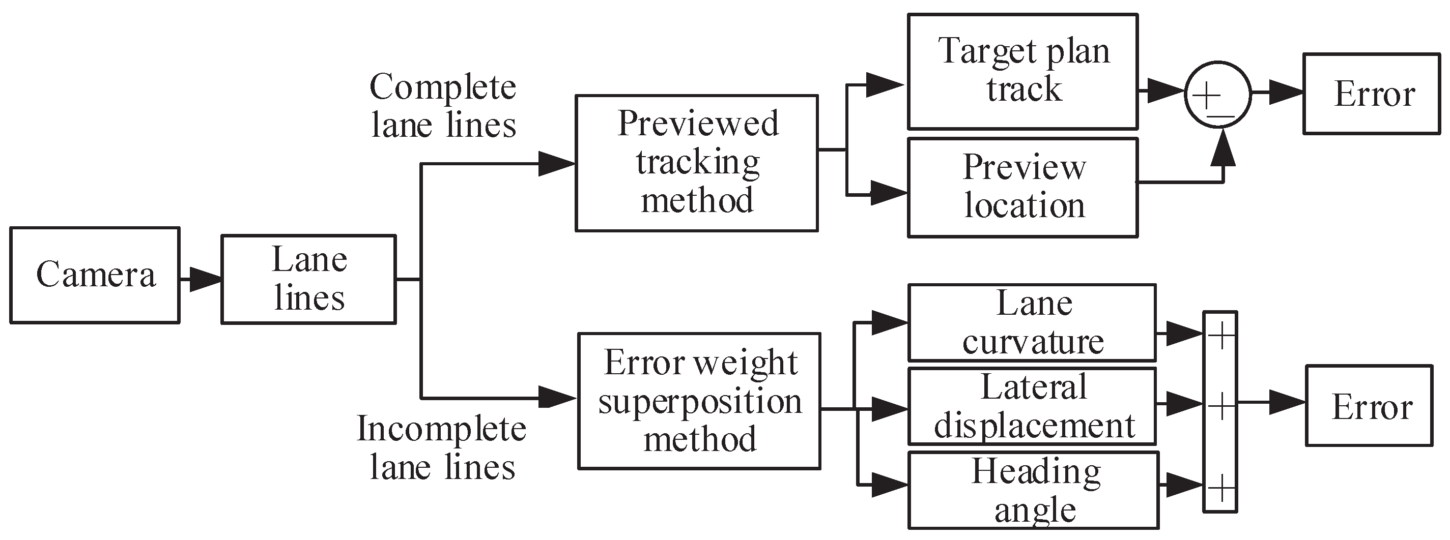
If an EV-DFWI is controlled to run along the desired lane, the controller must output yaw moment M z according to the tracking error of the lane. Therefore, how to obtain the tracking error of the lane is very important. Generally speaking, the tracking error is obtained in two ways. When the cameras collect enough information about the lane lines, the reference path polynomial is fitted according to the direction of the lane line and the current location of the EV-DFWI. Then the displacement offset between the next time previewed point and the reference target path point is regarded as the controller input. The tracking error can be obtained accurately in this way; however, if the lane lines are collected incompletely, an error weight superposition method is used to determine the total error as the controller input. The structure of the LKC is shown in Figure 2. Next, the core modules of the LKC are discussed in detail.

Tracking Error Computing of the LKC

As previously mentioned, the tracking error is obtained in two ways according to the lane lines collection. The two tracking error computing methods are shown in Figure 3.
(1) Previewed tracking method for tracking error computing
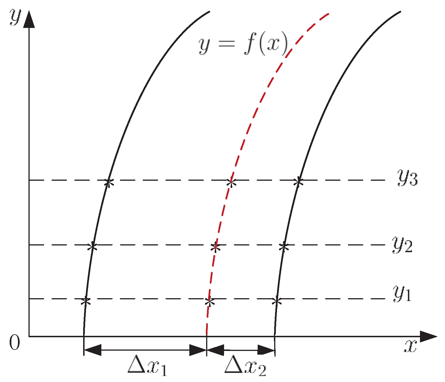
In order to acquire an ideal path, the lane line information and the current location of the vehicle should be acquired completely. The ideal path is not always the center line of the lane for a running EV. That is to say, the correction function of the LKC method will keep the vehicle running in the lane according to its current location, not along the center line of the lane. The ideal path is shown in Figure 4.
As shown in Figure 4, if the vehicle’s distances from the left and right lane lines are Δ x 1 and Δ x 2 respectively, the ideal path is the red dotted line. The ideal path can be obtained as follows.
a. The locations of the sampled points on the left lane line are ( x 11 , y 1 ), ( x 12 , y 2 ), ( x 13 , y 3 ), ⋯. The initial offset distance Δ x 1 is added to every sampled points to obtain the locations of the first group points ( x 11 + Δ x 1 , y 1 ), ( x 12 + Δ x 1 , y 2 ), ( x 13 + Δ x 1 , y 3 ), ⋯.
b. The locations of the sampled points on the right lane line are ( x 21 , y 1 ), ( x 22 , y 2 ), ( x 23 , y 3 ), ⋯. The initial offset distance Δ x 2 is subtracted from every sampled points to obtain the locations of the second group points ( x 21 Δ x 2 , y 1 ), ( x 22 Δ x 2 , y 2 ), ( x 23 Δ x 2 , y 3 ), ⋯.
c. For the same Y-axle values, the locations of the third group points are obtained as ( 1 2 ( ( x 11 + Δ x 1 ) + ( x 21 Δ x 2 ) ) , y 1 ), ( 1 2 ( ( x 12 + Δ x 1 ) + ( x 22 Δ x 2 ) ) , y 2 ), ( 1 2 ( ( x 13 + Δ x 1 ) + ( x 23 Δ x 2 ) ) , y 3 ), ⋯.
d. A curve is matched according to the locations of the third group points, which is the ideal path under the current condition.
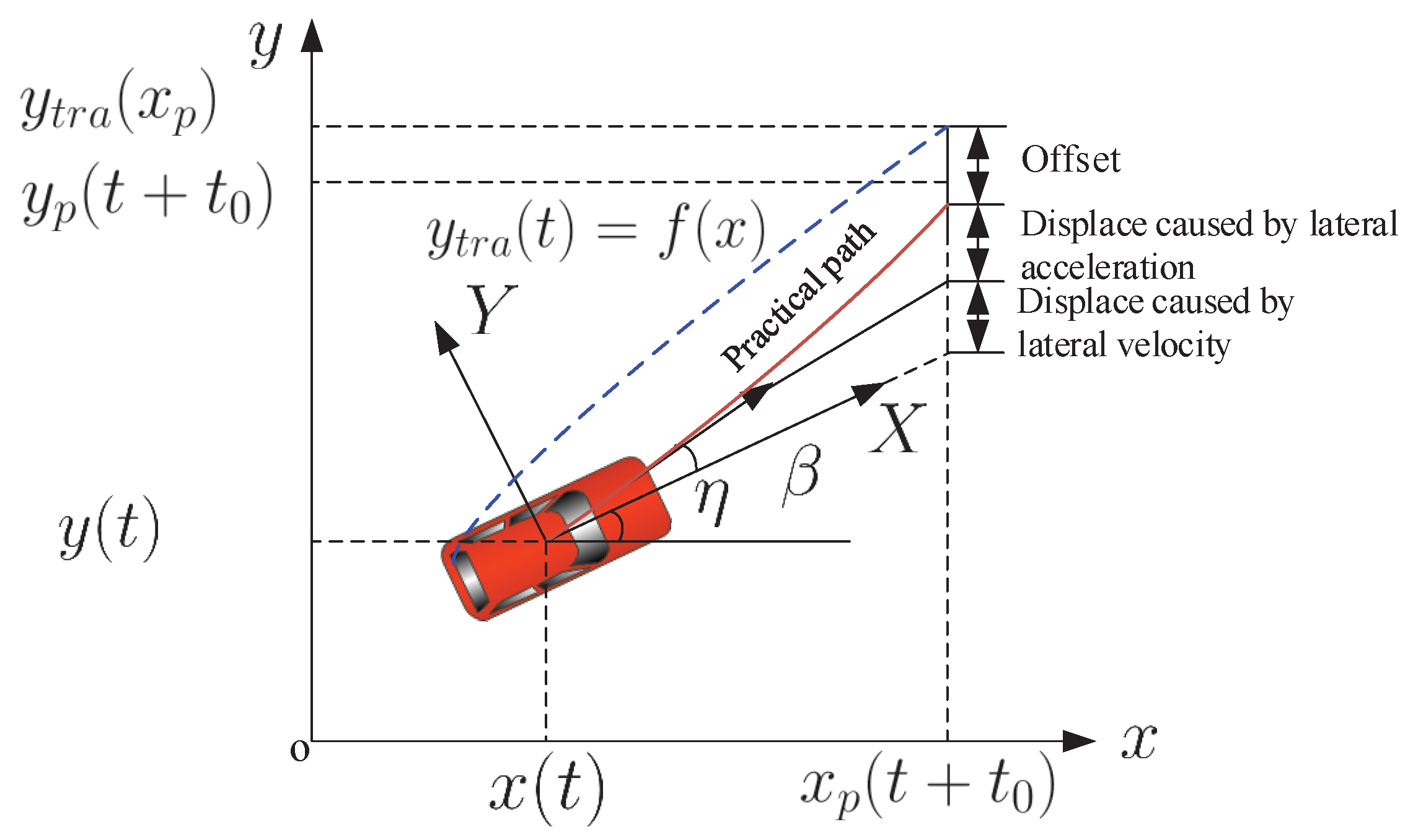
An absolute coordinate, oxy, and vehicle coordinate, OXY, shown in Figure 5, were built to construct the driver preview tracking model. As shown in Figure 5, the vehicle’s location is ( x t , y t ) in the absolute coordinate at t instant. The target trajectory function is y t r a = f ( x ) . The previewed time is t 0 = d v , where d is the previewed distance, v is the vehicle velocity. Then after time t 0 , the vehicle’s abscissa is
x p ( t + t 0 ) = x ( t ) + t 0 v cos ( β + η ) ,
where x p is the vehicle abscissa of the next instant, η is the yaw angle. According to the target trajectory function, after time t 0 , the target trajectory ordinate with this abscissa is
y t r a ( x p ) = f ( x p ( t + t 0 ) ) = f ( x ( t ) + t 0 v cos ( β + η ) ) .
According to the displacement computing function, after previewed time t 0 , the ordinate is
y p ( t + t 0 ) = y ( t ) + t 0 y ˙ ( t ) + 1 2 y ¨ ( t ) t 0 2 .
Then, the offset λ is the error between the previewed ordinate and the computed ordinate according to the target trajectory.
λ = f ( x ( t ) + t 0 v cos ( β + η ) ) [ y ( t ) + t 0 y ˙ ( t ) + 1 2 y ¨ ( t ) t 0 2 ] .
(2) Error weight superposition method for tracking error computing
The lane line information collected by the cameras may be not enough because of muddy road, insufficient light, etc. Then the polynomial of the lane line can not be fitted to obtain the target trajectory. In this case, an error weight superposition method is proposed to obtain the total error as the controller input. The error weight superposition method considers the influence to lane departure from the road curvature, lateral position relative to the lane center, and vehicle yaw angle. The controller input is composed of every factor with respective weights.
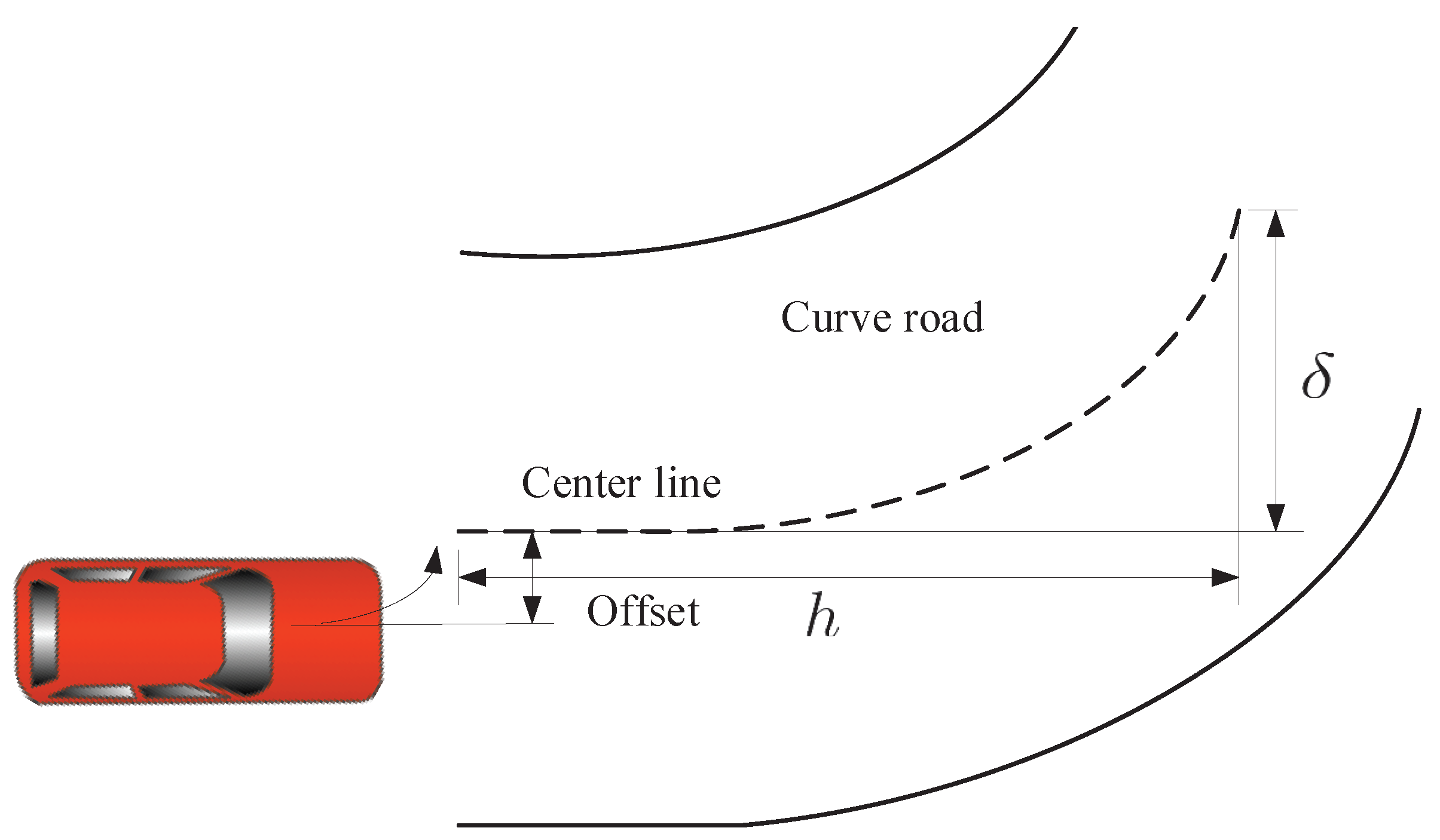
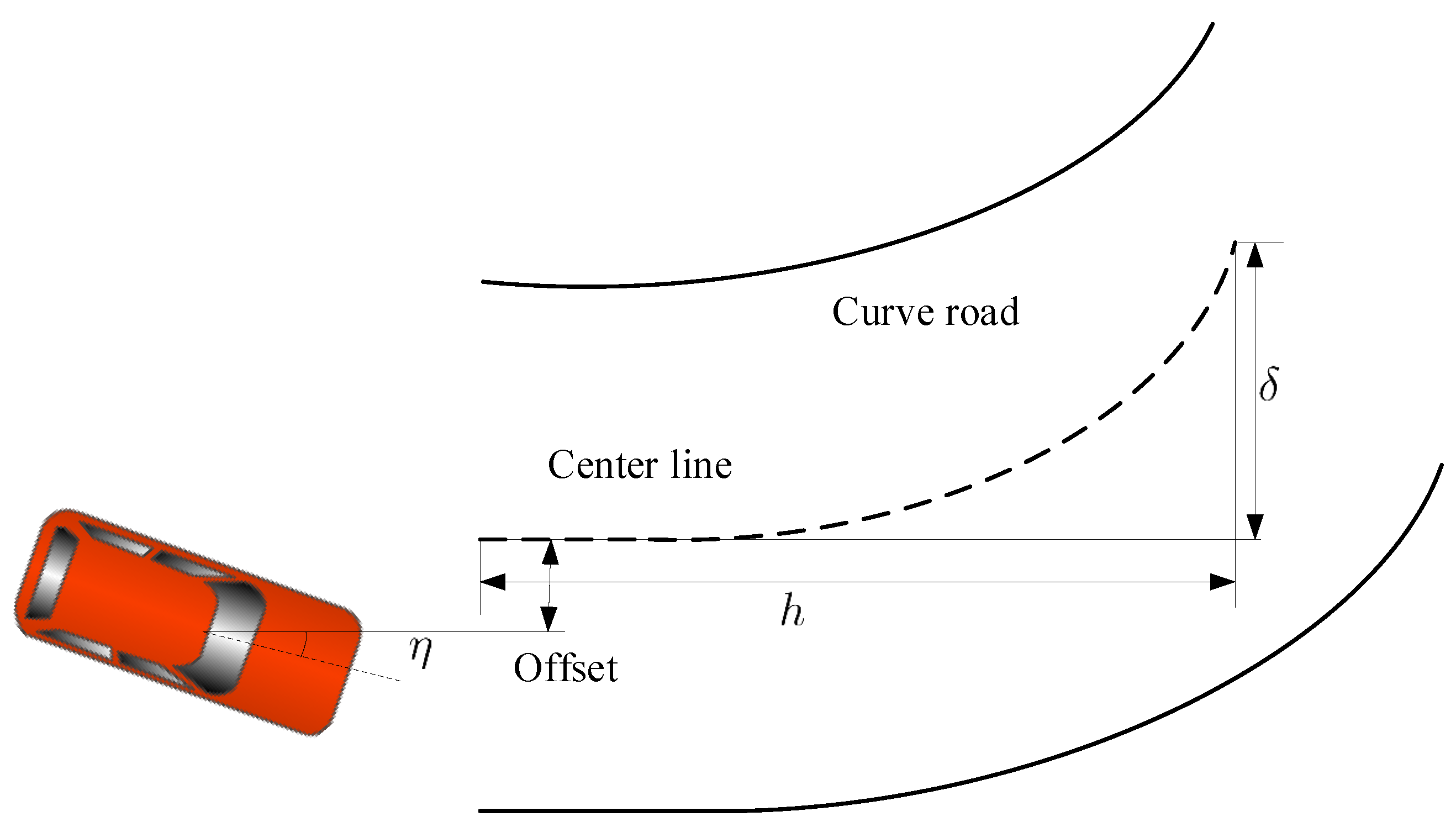
If a vehicle is controlled to run within a lane, the road curvature and the departure from the center of the road should be provided. In this case, we can understand this issue from the relative curvature. For example, a vehicle generates a yaw angle when it runs along a straight road. The lane lines collected by cameras may still curve. Then the actuator regards this case as the vehicle running on a curve road unless the heading angle is corrected to obtain the straight lane lines by the cameras. Therefore, the offset between the vehicle and road is composed of three parts, the road curvature, offset between vehicle’s location and road center line, and vehicle yaw angle. The lane center line can be obtained by the left and right lane lines. Then the curvature of the lane center line determines the lane curvature, which can be calculated by
k c u r v e = δ h ,
where h is the horizontal offset, δ is the vertical offset, as shown in Figure 6. If the vehicle’s vertical center line deviates from the road center line as shown in the figure, and runs into the curve lane along the tangent, the vehicle must be adjusted to return to the road center line and runs along the curve line. Therefore, the direction angle which needs to be adjusted can be described as
θ = p 1 δ h + p 2 λ ,
where p 1 and p 2 are the coefficients.
However, the vehicle may not run parallel to the lane lines, or run into the curved lane along the tangent, i.e., the vehicle deviates the road center line with a yaw angle as shown in Figure 7. In this case, the vehicle must be adjusted to return to the road center line for running along the curve line. The yaw angle should also be adjusted. Therefore, the total error e can be calculated as
e = p 1 δ h + p 2 λ + p 3 η ,
where p 3 is the coefficient. Then, we can calculate the necessary adjusted angle for keeping the car running along the lane by Equation (8).

3. Design of the Lane Keeping Controller Based on NoS-FT Control Method

The classic lane control method usually outputs an additional steering wheel angle by the PID algorithm according to the relative relation between the vehicle location information and lane center line. This control method is mature and reliable, but not robust. When the system suffers a sudden change of external force, it will generate an obvious oscillation, and the oscillation is difficult to decrease. Some scholars proposed some improved control algorithms in the references. These algorithms have better robust, but need larger memory space, and become complex which may lead to poor stability.
The purpose of this article is to design a NoS-FT controller to keep the EV-DFWI running along the desired route. The designed controller generates a additional direct yaw moment M z for this purpose. In fact, The additional yaw moment is the torque difference among the four driving wheels. This method is faster and more direct.
The objective of the controller is to ensure the total error e being zero. Therefore, the necessary adjusted angle of the body is the state, and the additional yaw moment is the controller input. The relation between the total error and additional yaw moment is simplified to a first-order plant.
x ˙ e = u d y m = M z .
Then, the designed NoS-FT lane keeping controller is
u d y m = k u sign ( x e ) | x e | α u , 0 < α u < 1 , k u > 0 .
According to Equations (9) and (10), we obtain
x ˙ e = k u sign ( x e ) | x e | α u .
The solution of Equation (11) is
x e ( t ) = sign ( x e ( 0 ) ) ( | x e ( 0 ) | 1 α u k u ( 1 α u ) t ) 1 1 α u , 0 < t | x e ( 0 ) | 1 α u ( 1 α u ) k u 0 , t > | x e ( 0 ) | 1 α u ( 1 α u ) k u .
Next, we prove the system can be stabilized by the designed NoS-FT controller via the direct Lyapunov method. The selected Lyapunov function is
V ( x e ) = 1 2 x e 2 .
The derivation of Equation (13) is
V ˙ ( x e ) = x e x ˙ e .
Substituting Equation (11) into Equation (14), one obtains
V ˙ ( x e ) = k u x e sign ( x e ) | x e | α u = k u | x e | 1 + α u < 0 ,
which means that the designed NoS-FT controller can stabilize the vehicle’s driving deviation to zero, i.e., the controller can keep the vehicle running in the desired lane.

4. Simulation and Analysis

In this section, the simulation of the control system (11) was conducted under a vehicle velocity of 90 km/h. The designed NoS-FT controller was compared with the PID controller in the simulation to verify its efficiency. We classify the vehicle running conditions into four types: straight road, constant curvature road, varied curvature road, and S-bend road. Next, we present the simulations of the four conditions separately. The vehicle parameters used in the simulation are in Table 1.
We first simulated the straight running condition. In the simulation, the car was located on the right of the white line that separates the road into two lanes, as shown in Figure 8. The simulation results are shown in Figure 9. From Figure 9, we can see that the lateral displacement under the NoS-FT controller is smaller than the PID controller. The displacement under the NoS-FT controller tends to zero after 75 m of longitudinal displacement, but the displacement under the PID controller tends to zero after 150 m of longitudinal displacement.
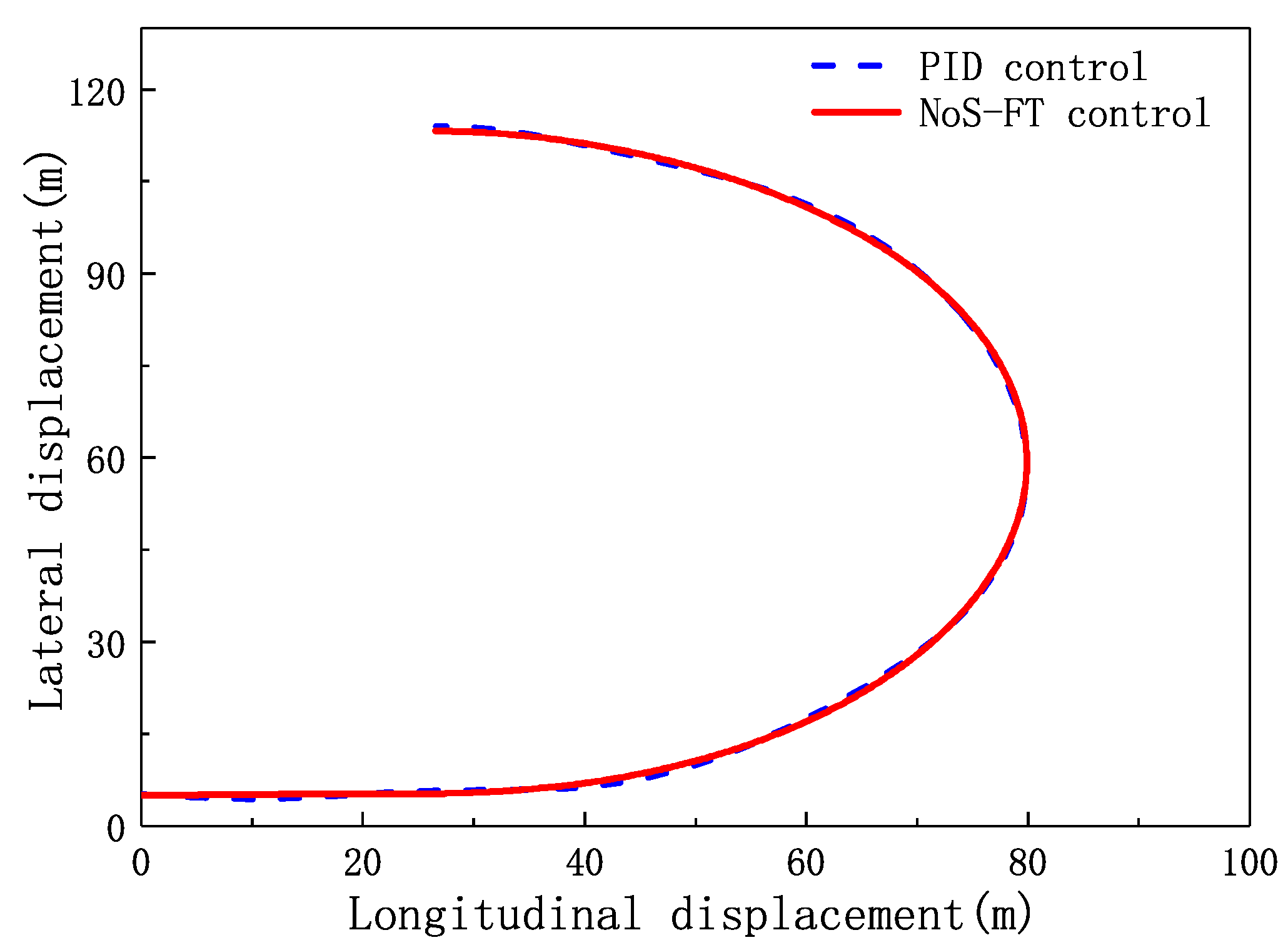
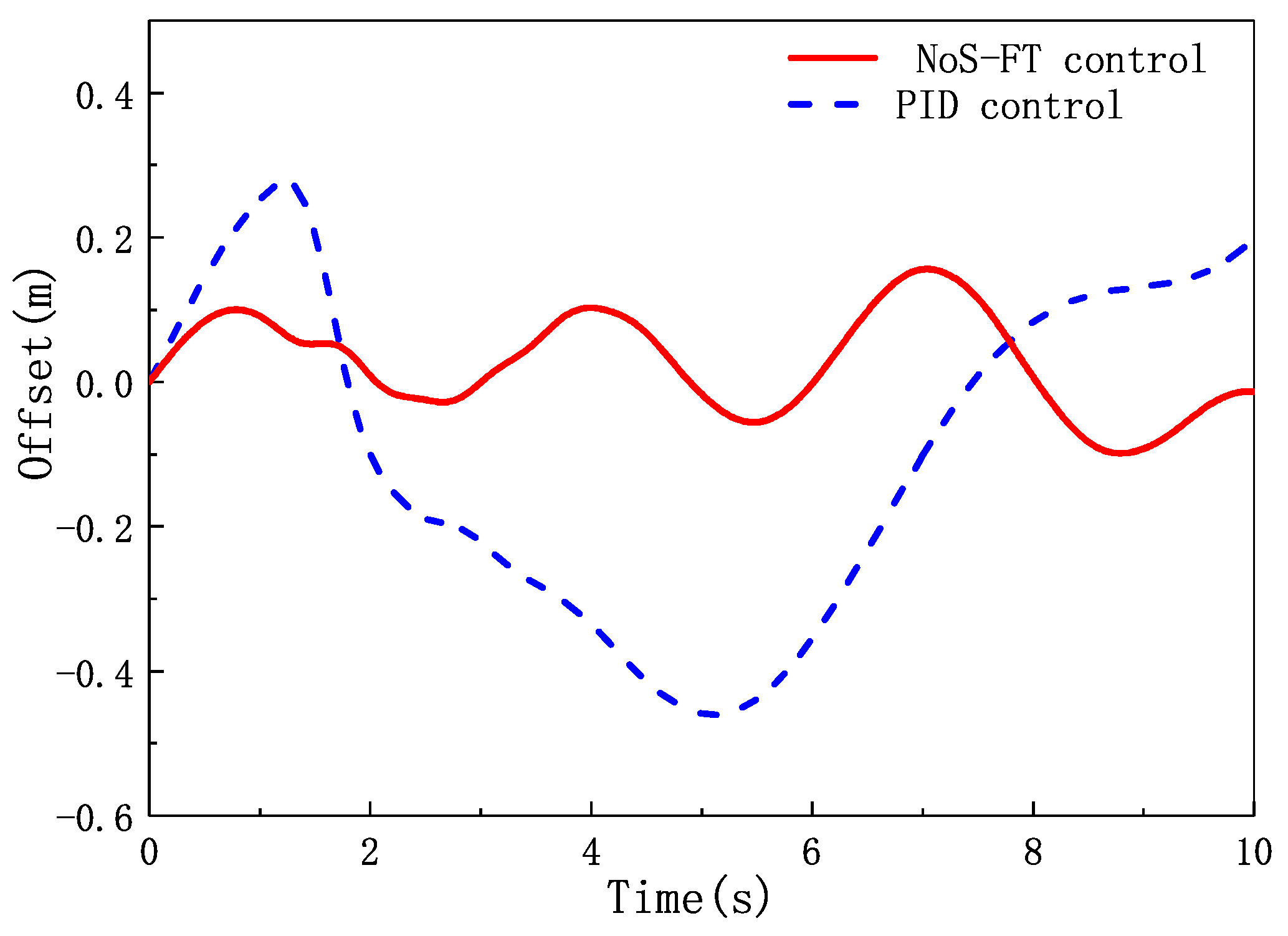
The second simulation was carried out using the constant curvature road, which is shown in Figure 10. In this simulation, the car was located in one lane, and the input steering wheel angle was zero. The simulation results are shown in Figure 11 and Figure 12. The NoS-FT controller and PID controller both keep the car running along the constant curvature as shown in Figure 11, and the NoS-FT controller has a smaller offset than the PID controller as shown in Figure 12. The offset is limited within –0.1 to 0.15 m under the NoS-FT controller, but within –0.5 to 0.28 m under the PID controller.
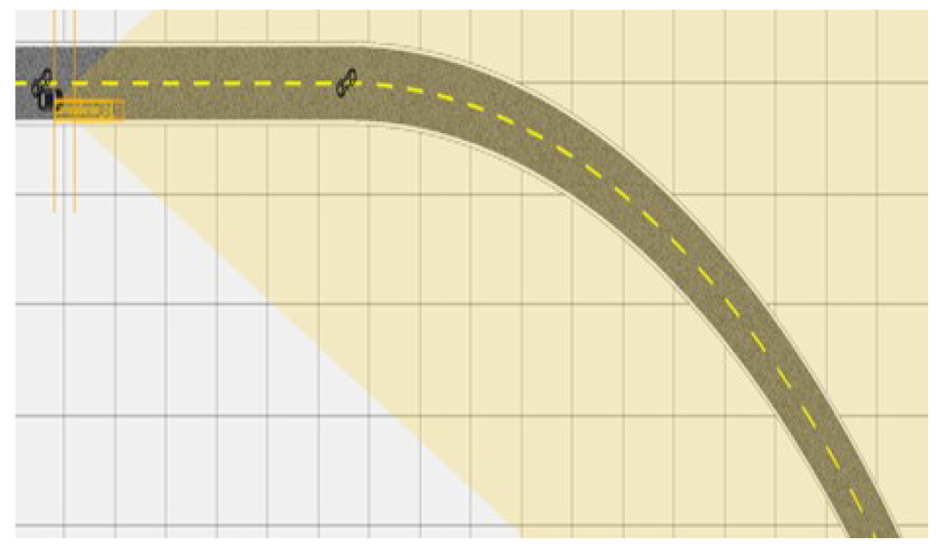
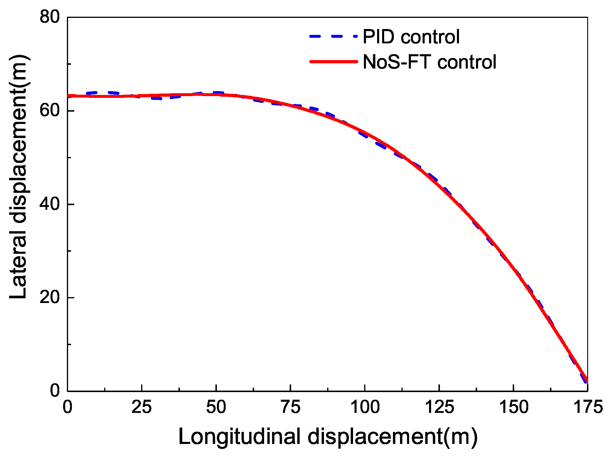
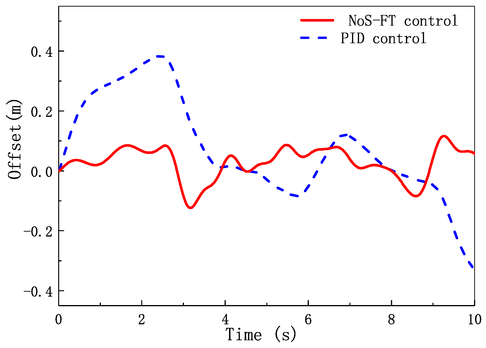
Another common condition is that the car runs on a varied curvature road. In the simulation, the input steering wheel angle is zero. The road model is shown in Figure 13. The car runs on the straight part, then runs into the varied curvature part. Figure 14 is the car’s displacements under different controllers, which shows that the NoS-FT and PID controllers are both effective for the varied curvature road. Figure 15 shows that the offset is between –0.12 and 0.1 m under the NoS-FT controller, which is much smaller than the PID controller that is between –0.35 and 0.4 m.
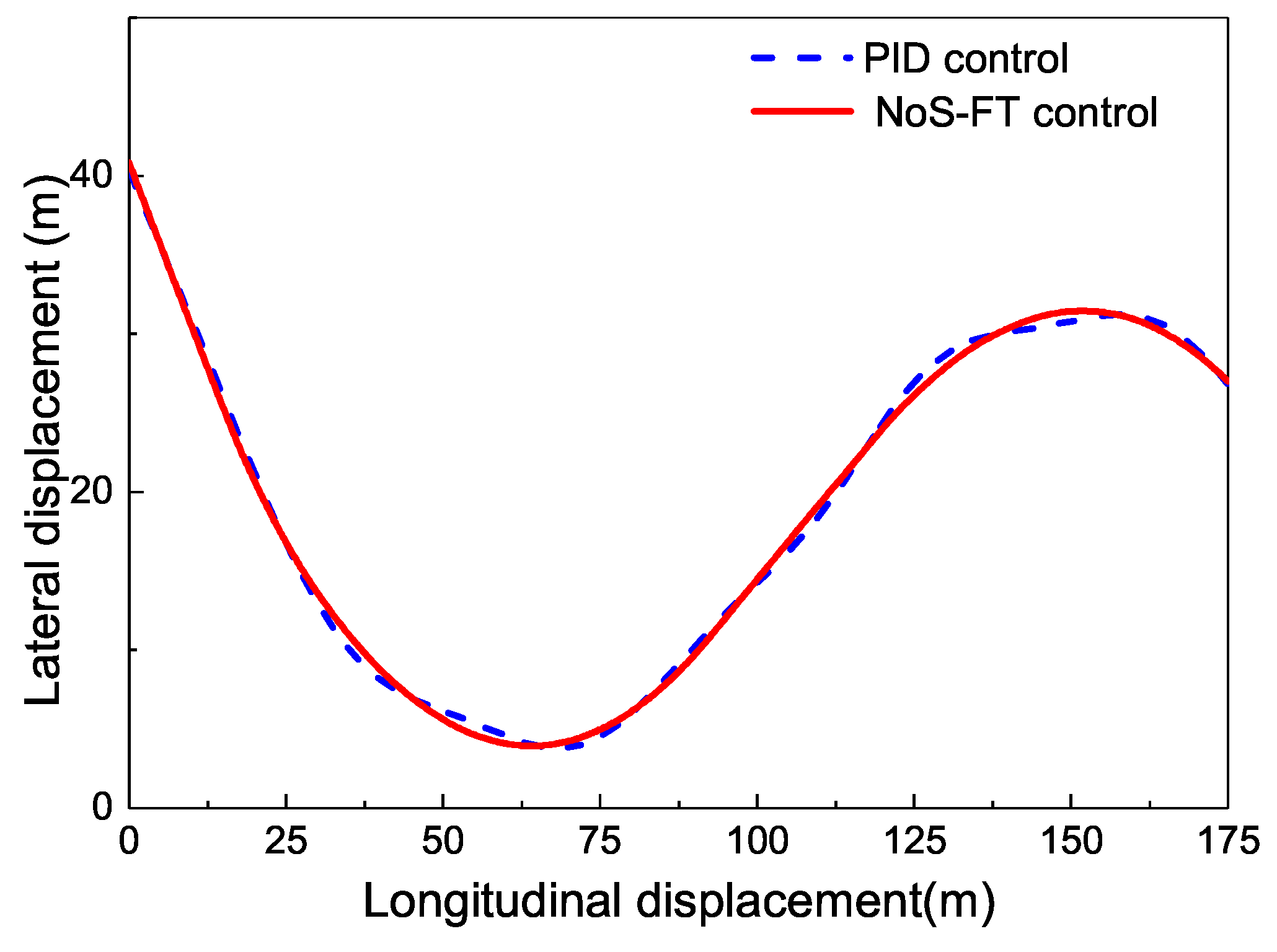
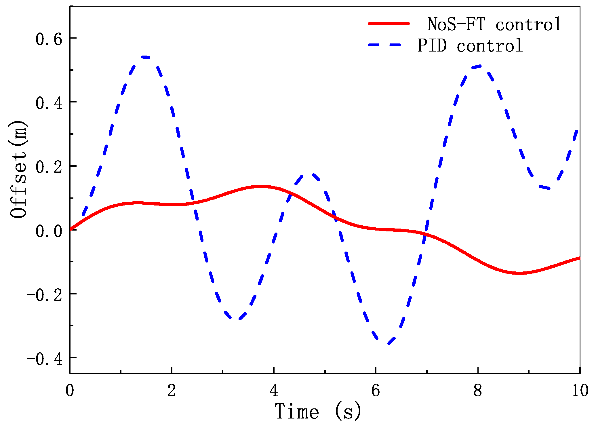
The last condition is the S-bend curvature road, which is shown in Figure 16. The car runs in one lane, and the car’s steering wheel angle is zero. The car’s displacements under different controllers are shown in Figure 17. From which we can see that the two controllers can keep the car running along the desired lane. But the offset is within –0.12 to 0.15 m under the NoS-FT controller, which is much smaller than –0.35 to 0.55 m under the PID controller as shown in Figure 18.

5. Conclusions

In this article, an LKC model of an EV-DFWI is built for to design a controller to improve the output response and robustness of the LKC. Then, based on the model, both a previewed tracking method and error weight superposition method are proposed to compute the tracking errors for the following designed controller to enable the vehicle to run along the desired lane. Based on the NoS-FT control method, the lane keeping controller is designed to control four driving wheels to reduce the total tracking error. The designed controller is proved by the direct Lyapunov method that it can stabilize the vehicle in theory. Through the simulation of the designed NoS-FT controller and PID controller under the common four conditions, this paper achieves the following conclusions:
  • The designed NoS-FT controller can stabilize the lateral displacement of the EV-DFWI to zero faster than the PID controller running along a straight road.
  • The designed NoS-FT controller has a smaller offset and better effectiveness than the PID controller under other different conditions.

Author Contributions

Conceptualization, Q.M.; methodology, Q.M.; software, X.Z.; formal analysis, X.Z.; writing—original draft preparation, Q.M.; writing—review and editing, C.H. and Z.-Y.S. All authors have read and agreed to the published version of the manuscript.

Funding

This research was supported by Zhejiang Provincial Natural Science Foundation of China under Grant No. LZ21E050002, National Natural Science Foundation of China under Grant No. 61773237, Postgraduate Education and Teaching Reform Project of Hangzhou Dianzi University under Grant No. JXGG2020YB007.

Conflicts of Interest

The authors declare no conflict of interest.

Abbreviations

The following abbreviations are used in this manuscript:
EV-DFWIElectric Vehicle Driven by Four Wheels Independently
EVElectric Vehicle
NoS-FTNon-Smooth Finite-Time
LKCLane Keeping Control

References

  1. Zhang, J.; Sun, W.; Du, H. Integrated Motion Control Scheme for Four-Wheel-Independent Vehicles Considering Critical Conditions. IEEE Trans. Veh. Technol. 2019, 68, 7488–7497. [Google Scholar] [CrossRef]
  2. Merabet, A. Advanced Control for Electric Drives: Current Challenges and Future Perspectives. Electronics 2020, 9, 1762. [Google Scholar] [CrossRef]
  3. Lim, D.H.; Lee, M.Y.; Lee, H.S.; Kim, S.C. Performance Evaluation of an In-Wheel Motor Cooling System in an Electric Vehicle/Hybrid Electric Vehicle. Energies 2014, 7, 961–971. [Google Scholar] [CrossRef] [Green Version]
  4. Xu, Q.; Zhou, C.; Huang, H.; Zhang, X. Research on the Coordinated Control of Regenerative Braking System and ABS in Hybrid Electric Vehicle Based on Composite Structure Motor. Electronics 2021, 10, 223. [Google Scholar] [CrossRef]
  5. Yim, S. Vehicle Stability Control with Four-Wheel Independent Braking, Drive and Steering on In-Wheel Motor-Driven Electric Vehicles. Electronics 2020, 9, 1934. [Google Scholar]
  6. Han, K.; Choi, M.; Lee, B.; Choi, S.B. Development of a Traction Control System Using a Special Type of Sliding Mode Controller for Hybrid 4WD Vehicles. IEEE Trans. Veh. Technol. 2018, 67, 264–274. [Google Scholar] [CrossRef]
  7. Meng, Q.; Sun, Z.Y.; Shu, Y.; Liu, T. Lateral motion stability control of electric vehicle via sampled-data state feedback by almost disturbance decoupling. Int. J. Control 2019, 92, 734–744. [Google Scholar] [CrossRef]
  8. Li, Z.; Cui, G.; Li, S.; Zhang, N.; Tian, Y.; Shang, X. Lane Keeping Control Based on Model Predictive Control Under Region of Interest Prediction Considering Vehicle Motion States. Int. J. Automot. Technol. 2020, 21, 1001–1011. [Google Scholar] [CrossRef]
  9. Chen, W.; Zhao, L.; Wang, H.; Huang, Y. Parallel Distributed Compensation/H(infinity)Control of Lane-keeping System Based on the Takagi-Sugeno Fuzzy Model. Chin. J. Mech. Eng. 2020, 33, 1–13. [Google Scholar] [CrossRef]
  10. Salt Ducajú, J.M.; Salt Llobregat, J.J.; Cuenca, Á.; Tomizuka, M. Autonomous Ground Vehicle Lane-Keeping LPV Model-Based Control: Dual-Rate State Estimation and Comparison of Different Real-Time Control Strategies. Sensors 2021, 21, 1531. [Google Scholar] [CrossRef] [PubMed]
  11. Suryanarayanan, S.; Tomizuka, M. Appropriate Sensor Placement for Fault-Tolerant Lane-Keeping Control of Automated Vehicles. IEEE/ASME Trans. Mechatron. 2007, 12, 465–471. [Google Scholar] [CrossRef]
  12. Junyeon, H.; Kunsoo, H.; Hyukmin, N.; Hogi, J.; Hyungjin, K.; Paljoo, Y. Evaluation of lane keeping assistance controllers in HIL simulations. IFAC Proc. 2008, 41, 9491–9496. [Google Scholar]
  13. Katzourakis, D.I.; Lazic, N.; Olsson, C.; Lidberg, M.R. Driver Steering Override for Lane-Keeping Aid Using Computer-Aided Engineering. IEEE-ASME Trans. Mechatron. 2015, 20, 1543–1552. [Google Scholar] [CrossRef]
  14. Son, Y.S.; Kim, W.; Lee, S.H.; Chung, C.C. Robust Multirate Control Scheme With Predictive Virtual Lanes for Lane-Keeping System of Autonomous Highway Driving. IEEE Trans. Veh. Technol. 2015, 64, 3378–3391. [Google Scholar] [CrossRef]
  15. Merah, A.; Hartani, K.; Draou, A. A new shared control for lane keeping and road departure prevention. Veh. Syst. Dyn. 2016, 54, 86–101. [Google Scholar] [CrossRef]
  16. Shu, P.; Sagara, S.; Wang, Q.; Oya, M. Improved adaptive lane-keeping control for four-wheel steering vehicles without lateral velocity measurements. Int. J. Robust Nonlinear Control 2017, 27, 4154–4168. [Google Scholar] [CrossRef]
  17. Kang, C.M.; Lee, S.H.; Chung, C.C. Multirate Lane-Keeping System With Kinematic Vehicle Model. IEEE Trans. Veh. Technol. 2018, 67, 9211–9222. [Google Scholar] [CrossRef]
  18. Chu, Z.; Sun, Y.; Wu, C.; Sepehri, N. Active disturbance rejection control applied to automated steering for lane keeping in autonomous vehicles. Control Eng. Pract. 2018, 74, 13–21. [Google Scholar] [CrossRef]
  19. Kuo, C.Y.; Lu, Y.R.; Yang, S.M. On the Image Sensor Processing for Lane Detection and Control in Vehicle Lane Keeping Systems. Sensors 2019, 19, 1665. [Google Scholar] [CrossRef] [Green Version]
  20. Zhang, X.; Lin, H. Backstepping Fuzzy Sliding Mode Control for the Antiskid Braking System of Unmanned Aerial Vehicles. Electronics 2020, 9, 1731. [Google Scholar] [CrossRef]
  21. Ahn, T.; Lee, Y.; Park, K. Design of Integrated Autonomous Driving Control System that Incorporates Chassis Controllers for Improving Path Tracking Performance and Vehicle Stability. Electronics 2021, 10, 144. [Google Scholar] [CrossRef]
  22. Levant, A.; Yu, X. Sliding Mode Based Differentiation and Filtering. IEEE Trans. Autom. Control 2018, 63, 3061–3067. [Google Scholar] [CrossRef]
  23. Fridman, L. Technical Committee on Variable Structure and Sliding Mode Control. IEEE Control Syst. Mag. 2018, 38, 17–18. [Google Scholar]
  24. Zhang, C.; Yang, J.; Yan, Y.; Fridman, L.; Li, S. Semiglobal Finite-Time Trajectory Tracking Realization for Disturbed Nonlinear Systems via Higher-Order Sliding Modes. IEEE Trans. Autom. Control 2019, 65, 2185–2191. [Google Scholar] [CrossRef]
  25. Ding, S.; Mei, K.; Li, S. A new second-order sliding mode and its application to nonlinear constrained systems. IEEE Trans. Autom. Control 2018. [Google Scholar] [CrossRef]
  26. Ding, S.; Lu, L.; Wei, X.Z. Sliding Mode Direct Yaw-Moment Control Design for In-Wheel Electric Vehicles. IEEE Trans. Ind. Electron. 2017, 64, 6752–6762. [Google Scholar] [CrossRef]
  27. Ren, C.; Li, X.; Yang, X.; Ma, S. Extended State Observer-Based Sliding Mode Control of an Omnidirectional Mobile Robot With Friction Compensation. IEEE Trans. Ind. Electron. 2019, 66, 9480–9489. [Google Scholar] [CrossRef]
  28. Zhai, J.Y.; Song, Z.B. Adaptive sliding mode trajectory tracking control for wheeled mobile robots. Int. J. Control 2019, 92, 2255–2262. [Google Scholar] [CrossRef]
  29. Lei, J. Research on a kind of sliding mode lane keeping control for automated vehicles based on hybrid information of position and angular velocity. Optik 2016, 127, 9344–9360. [Google Scholar] [CrossRef]
  30. Mao, J.; Yang, J.; Li, S.; Yan, Y.; Li, Q. Output feedback-based sliding mode control for disturbed motion control systems via a higher-order ESO approach. IET Control Theory Appl. 2018, 12, 2118–2126. [Google Scholar] [CrossRef]
  31. Hu, C.; Qin, Y.; Cao, H.; Song, X.; Jiang, K.; Rath, J.J.; Wei, C. Lane keeping of autonomous vehicles based on differential steering with adaptive multivariable super-twisting control. Mech. Syst. Signal Process. 2019, 125, 330–346. [Google Scholar] [CrossRef]
  32. Hu, C.; Wang, Z.; Taghavifar, H.; Na, J.; Qin, Y.; Guo, J.; Wei, C. MME-EKF-based path-tracking control of autonomous vehicles considering input saturation. IEEE Trans. Veh. Technol. 2019, 68, 5246–5259. [Google Scholar] [CrossRef] [Green Version]
  33. Majumder, K.; Patre, B.M. Adaptive sliding mode control for asymptotic stabilization of underactuated mechanical systems via higher-order nonlinear disturbance observer. J. Vib. Control 2019, 25, 2340–2350. [Google Scholar] [CrossRef]
  34. Argha, A.; Su, S.W.; Zheng, W.X.; Celler, B.G. Sliding-mode fault-tolerant control using the control allocation scheme. Int. J. Robust Nonlinear Control 2019, 29, 6256–6273. [Google Scholar] [CrossRef]
  35. Sun, Z.Y.; Yun, M.M.; Li, T. A new approach to fast global finite-time stabilization of high-order nonlinear system. Automatica 2017, 81, 455–463. [Google Scholar] [CrossRef]
  36. Meng, Q.; Sun, Z.Y.; Li, Y. Finite-time Controller Design for Four-wheel-steering of Electric Vehicle Driven by Four In-wheel Motors. Int. J. Control Autom. Syst. 2018, 16, 1814–1823. [Google Scholar] [CrossRef]
  37. Meng, Q.; Qian, C.; Sun, Z.Y. Finite-time stability control of an electric vehicle under tyre blowout. Trans. Inst. Meas. Control 2019, 41, 1395–1404. [Google Scholar] [CrossRef]
  38. Lin, X.; Yang, Z.; Li, S. Finite-time boundedness and finite-time weighted L-2-gain analysis for a class of neutral type switched systems with time-varying delays. Int. J. Syst. Sci. 2019, 50, 1703–1717. [Google Scholar] [CrossRef]
  39. Ding, S.; Zhang, Z.; Chen, X. Guidance law design based on non-smooth control. Trans. Inst. Meas. Control 2013, 35, 1116–1128. [Google Scholar] [CrossRef]
  40. Meng, Q.; Zhao, T.; Qian, C.; Sun, Z.; Ge, P. Integrated stability control of AFS and DYC for electric vehicle based on non-smooth control. Int. J. Syst. Sci. 2018, 49, 1518–1528. [Google Scholar] [CrossRef]
  41. Xia, C.; Li, S.; Shi, Y.; Zhang, X.; Sun, Z.; Yin, W. A Non-Smooth Composite Control Approach for Direct Torque Control of Permanent Magnet Synchronous Machines. IEEE Access 2019, 7, 45313–45321. [Google Scholar] [CrossRef]
Figure 1. The bike model of the electric vehicle driven by four wheels independently (EV-DFWI).
Electronics 10 00760 g001
Figure 2. The structure of the lane keeping control.
Electronics 10 00760 g002
Figure 3. The computing methods for tracking error of the lane keeping control.
Electronics 10 00760 g003
Figure 4. The ideal path of a HEV-DFWI.
Electronics 10 00760 g004
Figure 5. The vehicle locations in the absolute coordinate and vehicle coordinate ( β is the sideslip angle of vehicle, η is the yaw angle).
Electronics 10 00760 g005
Figure 6. The road curvature computing (h is the horizontal offset, δ is the vertical offset).
Electronics 10 00760 g006
Figure 7. The vehicle runs into a curve lane with a yaw angle (h is the horizontal offset, δ is the vertical offset, η is the yaw angle).
Electronics 10 00760 g007
Figure 8. The straight road used in the simulation (the X axle is the longitudinal displacement, the Y axle is the lateral displacement).
Electronics 10 00760 g008
Figure 9. The displacements of the car on a straight road controlled by different controllers.
Electronics 10 00760 g009
Figure 10. The car runs on a constant curvature road (the X axle is the longitudinal displacement, the Y axle is the lateral displacement).
Electronics 10 00760 g010
Figure 11. The traveling track of the car runs on a constant curvature road under different controllers.
Electronics 10 00760 g011
Figure 12. The offset of the car runs on a constant curvature road under different controllers.
Electronics 10 00760 g012
Figure 13. The car runs on a varied curvature road (the X axle is the longitudinal displacement, the Y axle is the lateral displacement).
Electronics 10 00760 g013
Figure 14. The traveling track of the car runs on a varied curvature road under different controllers.
Electronics 10 00760 g014
Figure 15. The offset of the car runs on a varied curvature road under different controllers.
Electronics 10 00760 g015
Figure 16. The car runs on a S-bend curvature road (the X axle is the longitudinal displacement, the Y axle is the lateral displacement).
Electronics 10 00760 g016
Figure 17. The traveling track of the car runs on a S-bend curvature road under different controllers.
Electronics 10 00760 g017
Figure 18. The total track error of the car runs on a S-bend curvature road under different controllers.
Electronics 10 00760 g018
Table 1. Vehicle parameters.
ParametersValue
Mass m/kg1800
Rotary inertia I z / kg · m 2 3000
Length between front axle and centroid l f / m 1.2
Length between rear axle and centroid l r / m 1.8
Lateral stiffness of front axle C f / N · rad 1 –1500
Lateral stiffness of rear axle C r / N · rad 1 –1200
Publisher’s Note: MDPI stays neutral with regard to jurisdictional claims in published maps and institutional affiliations.