Article

Coil Design of a Wireless Power-Transfer Receiver Integrated into a Left Ventricular Assist Device

1
Department of Industrial and Information Engineering and Economics, University of L’Aquila, 67100 L’Aquila, Italy
2
Department of Astronautics, Electrical and Energetic Engineering, Sapienza University of Rome, 00185 Rome, Italy
*
Author to whom correspondence should be addressed.
Electronics 2021, 10(8), 874; https://doi.org/10.3390/electronics10080874
Submission received: 12 March 2021 / Revised: 31 March 2021 / Accepted: 4 April 2021 / Published: 7 April 2021
(This article belongs to the Section Bioelectronics)

Abstract

:
This study deals with the design of a near-field wireless power transfer (WPT) system applied to a left ventricular assist device (LVAD) to treat patients with heart-failure problems. An LVAD is an implanted electrically driven pump connected to the heart and is traditionally powered by batteries external to the human body via a percutaneous driveline cable. The main challenge of wirelessly powering an LVAD implanted deep in the human body is to transfer relatively high power with high efficiency levels. Here the optimal design of the primary and secondary WPT coils is proposed to improve the performance of the WPT, avoiding possible safety problems of electromagnetic fields (EMF). As a main result, an average power of 5 W is continuously delivered to the LVAD by the WPT system working at 6.78 MHz with a total (DC–to–DC) efficiency of approximately 65% for the worst-case configuration.

1. Introduction

In the coming years, the diffusion of advanced heart failure globally will significantly increase. By 2030, it is estimated that 8 million Americans will be suffering from this pathology [1]. Nowadays, organ transplantation is still the best way to treat this pathology, but since the demand for heart transplantation dramatically exceeds organ supply, new technologies were developed to overcome this problem. A possible solution is the adoption of the left ventricular assist device (LVAD), which is an implanted medical device based on an electric pump used to support the blood circulation of advanced-heart-failure patients. The continuous operation of the LVAD is ensured by batteries external to the body, connected to the implanted device via a percutaneous driveline. The LVAD wearer has a driveline cable protruding from the abdomen connected to an external power supply (i.e., batteries), usually placed in a vest or belt, as shown in Figure 1a. Unlike active implanted medical devices (AIMDs), the LVAD has no internal batteries and continuously requires relatively large amounts of power. The LVAD was initially designed for a short operational period (< 2 years) for people awaiting a heart transplant, but much effort is now made to extend the duration of LVAD treatment, mainly due to the shortage of heart donors [2,3,4,5,6,7]. To prolong the life of an LVAD, some issues affecting the device need to be resolved, such as driveline infections (DLIs) caused by the presence of the driveline exit site, which is the main adverse event associated with use of the device [8].
The goal of this study is to develop a wireless power supply for an LVAD in which electrical energy is wirelessly transferred from an external transmitter integrated in the battery jacket to a receiver directly integrated into the implanted device. This solution allows for replacing the traditional wired power connection (i.e., driveline cable) with a near-field wireless power transfer (WPT) system based on magnetically coupled resonators. The challenging problems associated with this technology are the power to be supplied to the LVAD, range, tolerance for misalignment between transmitter and receiver coils, and the rapid decrease in efficiency that occurs as separation distance increases, even due to the presence of biological tissue.
There are many papers in the literature on the use of WPT technology to recharge AIMD batteries, which require low power and are subcutaneously implanted (e.g., pacemakers) [9,10,11]. Only a few studies delas with possible applications of WPT technology to deep high-power implants such as LVADs [12,13,14,15,16,17,18,19,20].
The solution proposed in [15] is based on a wireless coplanar energy-transfer system where the receiver unit has significant size and is implanted around the lung. The main disadvantage of this configuration is complexity, mostly for the implantation procedure. Simple architectures areproposed in [16,17,18] to power the LVAD, but no results are given regarding thermal and electromagnetic-field (EMF) safety. In [18,19], analysis only focuses on the influence of coil misalignment and on tissue heating. Two possible WPT solutions are proposed in [20]: (1) a subcutaneous receiving coil connected to the LVAD by a short driveline, completely inside the human body; and (2) an LVAD with a receiving circuit and coil, both integrated on it, as shown in Figure 1b. In this paper, the second solution is developed and extended. Section 2 outlines the materials and methods, including a detailed description of the LVAD characterization and the specifications of the WPT system. Then, the optimal design is validated by field and circuit simulations, and the obtained results are discussed in Section 3.

2. Materials and Methods

2.1. Main Design Specifications of WPT System for LVADs

Challenges in the design of a WPT system for LVADs include the following critical aspects:
(1)
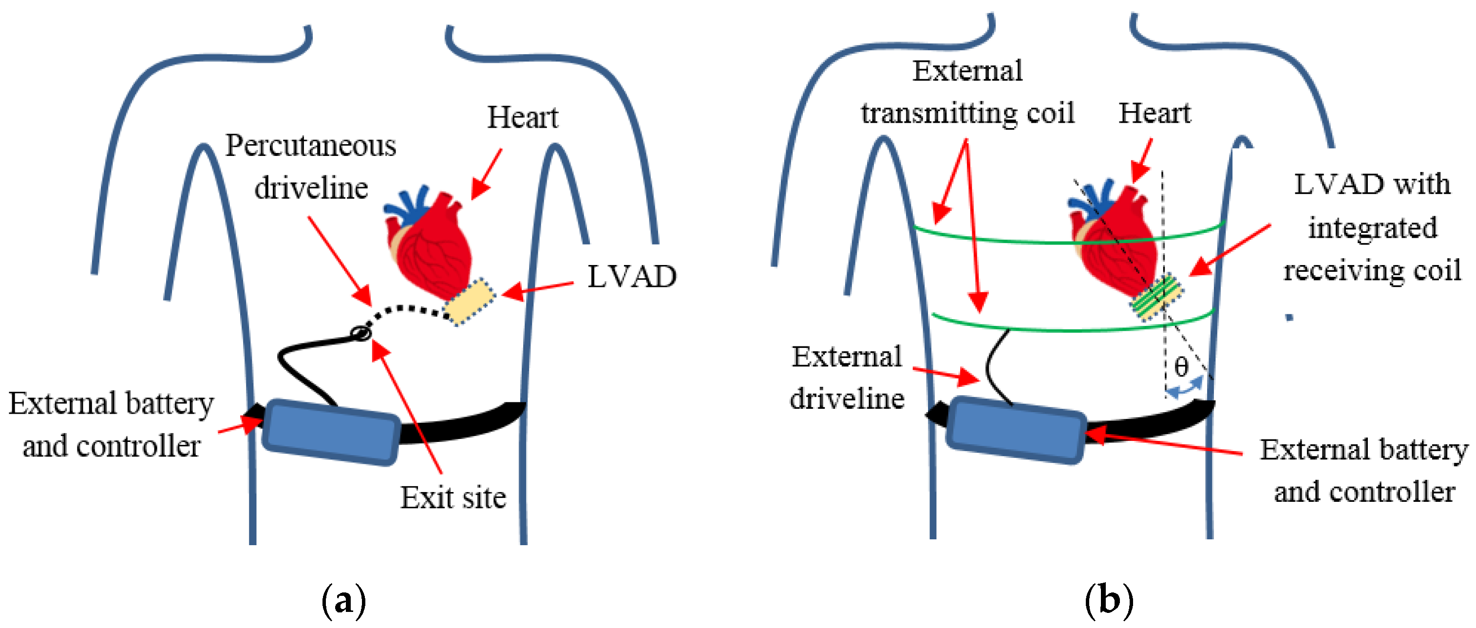
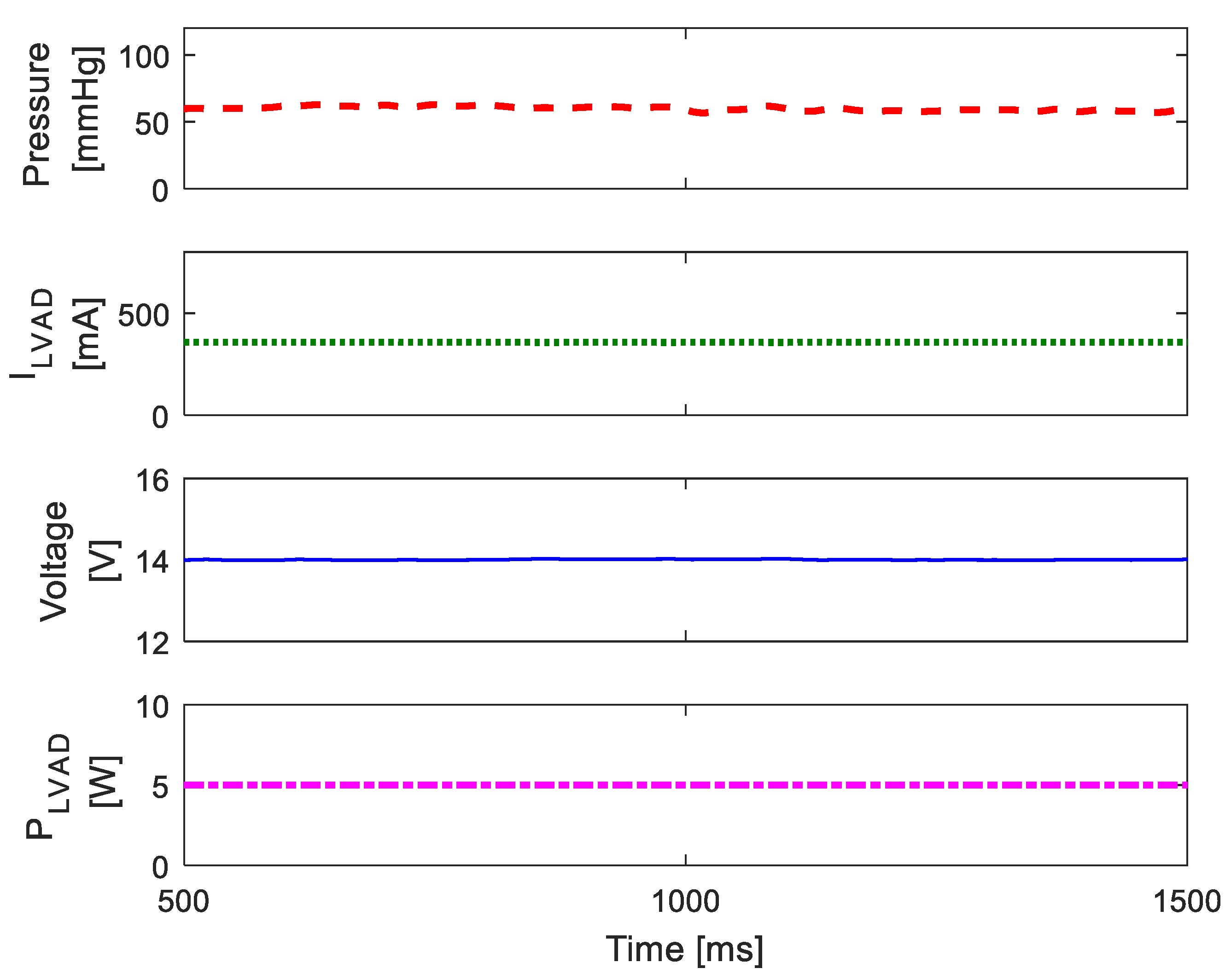
The LVAD, deeply implanted in the human body and attached to the left ventricle of the heart, must be continuously powered with 5 W of average power and 20 W of peak power under any operating condition;
(2)
The WPT transmitter must provide a fairly uniform field over a relatively large region, as the exact location of the implanted LVAD depends on the physical conformation of the patient;
(3)
Implanted WPT components must be very compact and light to be easily integrated into the LVAD;
(4)
The WPT system must comply with electromagnetic-field (EMF) safety standards and regulations.
To meet all these requirements, the design and optimization of the WPT coil system is very important in order to find the best trade-off between performance, size, weight, and safety.

2.2. LVAD Characterization

The LVAD is a high-power implant that is deeply implanted in the human body. The hydraulic pump is driven by a brushless DC electric motor that permits to adjust flow and blood pressure with high precision. Traditionally, the electric motor of the implanted pump is powered by an external battery. Here, a wireless power system is proposed to overcome the DLI problem. Initially, experimental tests on a real LVAD were needed to know the exact behavior of electrical quantities over time, since this knowledge plays a key role in the proper design of a wireless charging system. An experiment was then performed to measure electrical quantities in a commercial LVAD (Abbot HeartMate III [21]). To this aim, a simple mock circulatory loop (MCL) was built to simulate the real working conditions of the device. The MCL was composed of several components as shown in Figure 2. A liquid tank with maximal capacitance of 2 L was used as reservoir. The liquid tank was connected to the LVAD using a transparent polyvinyl chloride (PVC) tube with an internal diameter of 19 mm. To measure volumetric flow through the hydraulic loop, a hall-effect-based flow sensor was placed between tank and LVAD pump. The PVC tube was connected directly to the inlet port of the pump, fixed in a horizontal position. At the outlet port of the LVAD, digital pressure sensor Honeywell ABPDANT005PGAA5 was used to measure liquid pressure at the outlet port. The outlet port was connected through 40 cm of the same PVC tube to the clamp resistor. This last was composed of an electro-actuated valve that permitted to modify loop hydraulic resistance in real time to maintain physiological pressure. The blood was simulated adopting an equivalent viscosity fluid composed of 35% glycerin and 65% water. An electronic acquisition system was used to record MCL and LVAD parameters. The acquisition system was based on an Atmel ATmega328 microcontroller, which acquired data from the liquid-flow and pressure sensors. It was also used to adjust the setting of the clamp resistor. The acquisition system monitored electrical parameters in terms of voltage and pump current. For this scope, an INA219 acquisition IC with a 10 mΩ shunt resistor was adopted. Acquired data were sent to the PC via USB connection for postprocessing. Electrical and hydraulic parameters were recorded for several operation conditions. The pump was programmed with a rotational speed of 5500 rpm, and the valve was adjusted to obtain mean liquid pressure of 60 mmHg. Real-time electrical data in terms of transient voltage, current, and power, and hydraulic data in terms of pressure were recorded for a period of 1 s. Measured results (pressure, current, voltage, power) are shown in Figure 3. Mean power requested by the device was PLVAD = 4.95 W with DC voltage level VLVAD = 14 V. Thus, the LVAD in our study is modeled as a simple resistor of a value of RL = VLVAD2/PLVAD ≅ 40 Ω.

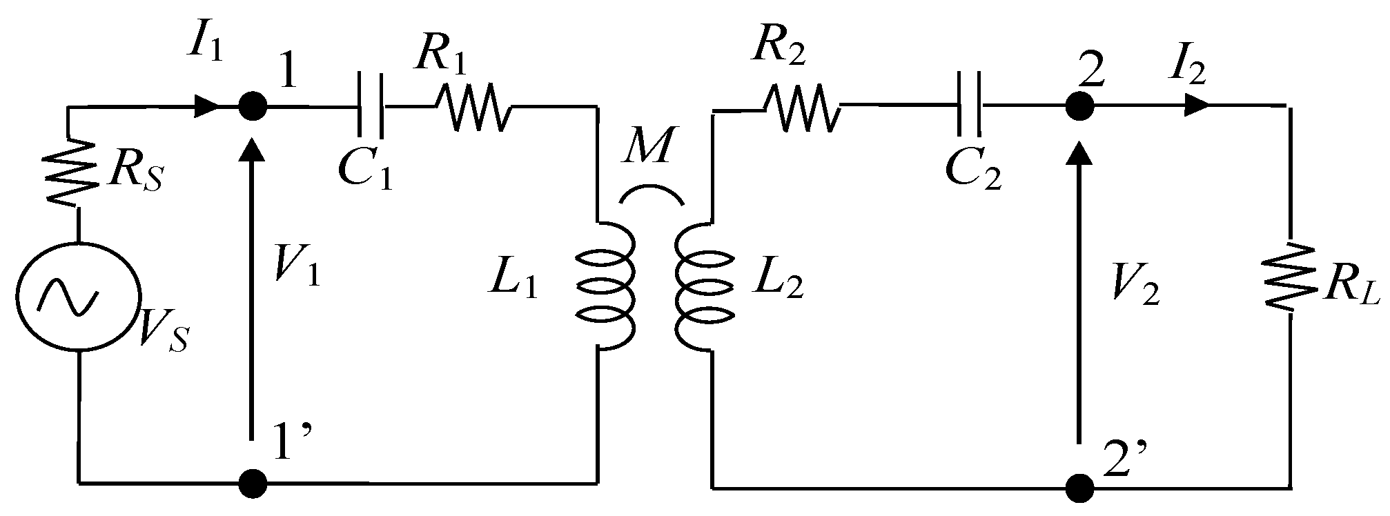
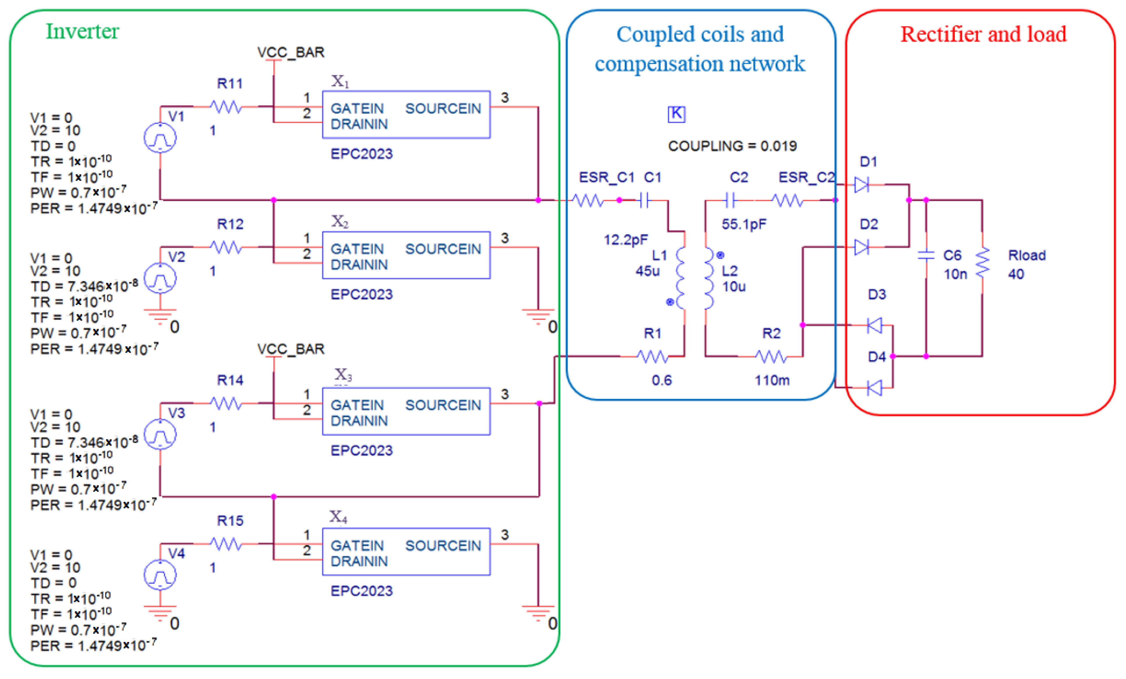
2.3. Wireless Powering System

WPT systems are traditionally divided into two main categories: far- and near-field WPTs. Far-field systems are based on microwave energy transfer where electrical energy is transmitted by electromagnetic field at a radio frequency (RF). The near (inductive) WPT field is mainly based on magnetic-resonance technology where energy is transferred by the magnetic field produced by coils. In biomedical applications, especially when significant power is required by the implanted device, near-field WPT is the most suitable technology because it reduces coil losses and is less sensitive to biological tissues attenuation than RF waves. [22]. Thus, in the following, a near-field WPT technology is adopted.

2.3.1. Near-Field WPT System

A simplified equivalent circuit of a near-field WPT system is shown in Figure 4, where two coils are modeled by self-inductances (L1 and L2) and resistances (R1 and R2). The coupling between inductors is modeled by mutual inductance M. The coupling factor k is defined as
k = M L 1 L 2
To improve the performance of the system, the resonance condition is obtained by compensating the inductive reactance of primary and secondary coils by the capacitors. The simplest topology of the compensation network is typically realized with capacitors connected in series or in parallel [23,24]. In the series–series (SS) compensation topology, capacitors are series-connected on both transmitting and receiving sides. The simplified equivalent circuit is powered by a sinusoidal voltage source VS with internal resistance RS, and the load is modeled by power resistor RL, at resonance. The lumped parameters of the coils can be analytically calculated or, in the case of a complex configuration, can be numerically calculated at the frequency of interest solving magnetoquasistatic (MQS) field equations by the finite-element method (FEM) [25]. Then, parameters of compensation capacitors C1 and C2 are calculated as described in [26]. Analysis of the WPT equivalent circuit, performed by circuit simulators or MATLAB code, permits to calculate the electrical performance of the system in terms of efficiency η and transferred power PL to the load. Efficiency η is the ratio between real power PL on the load and input real power P1 at port 1–1′ of the equivalent circuit.

2.3.2. Selection of Operational Frequency

For a near-field WPT applied to a deep implant, the selection of the resonance (operational) frequency is very important. The coil coupling in a near-field WPT is based on the Faraday law of induction. A previous work [26] showed that the optimal frequency for a deep implant is around f = 4 MHz to obtain the maximal electromotive force for a small coil located well inside the human body within the limits of EMF safety. However, since 4 MHz is not in the unlicensed frequency band, the industrial, scientific, and medical (ISM) frequency of 6.78 MHz was adopted for the proposed application, which is the closest ISM frequency to 4 MHz. After selecting the operational frequency, the next problem is the definition of the most suitable configuration of the WPT coils. The design of the primary and secondary coils is described below.

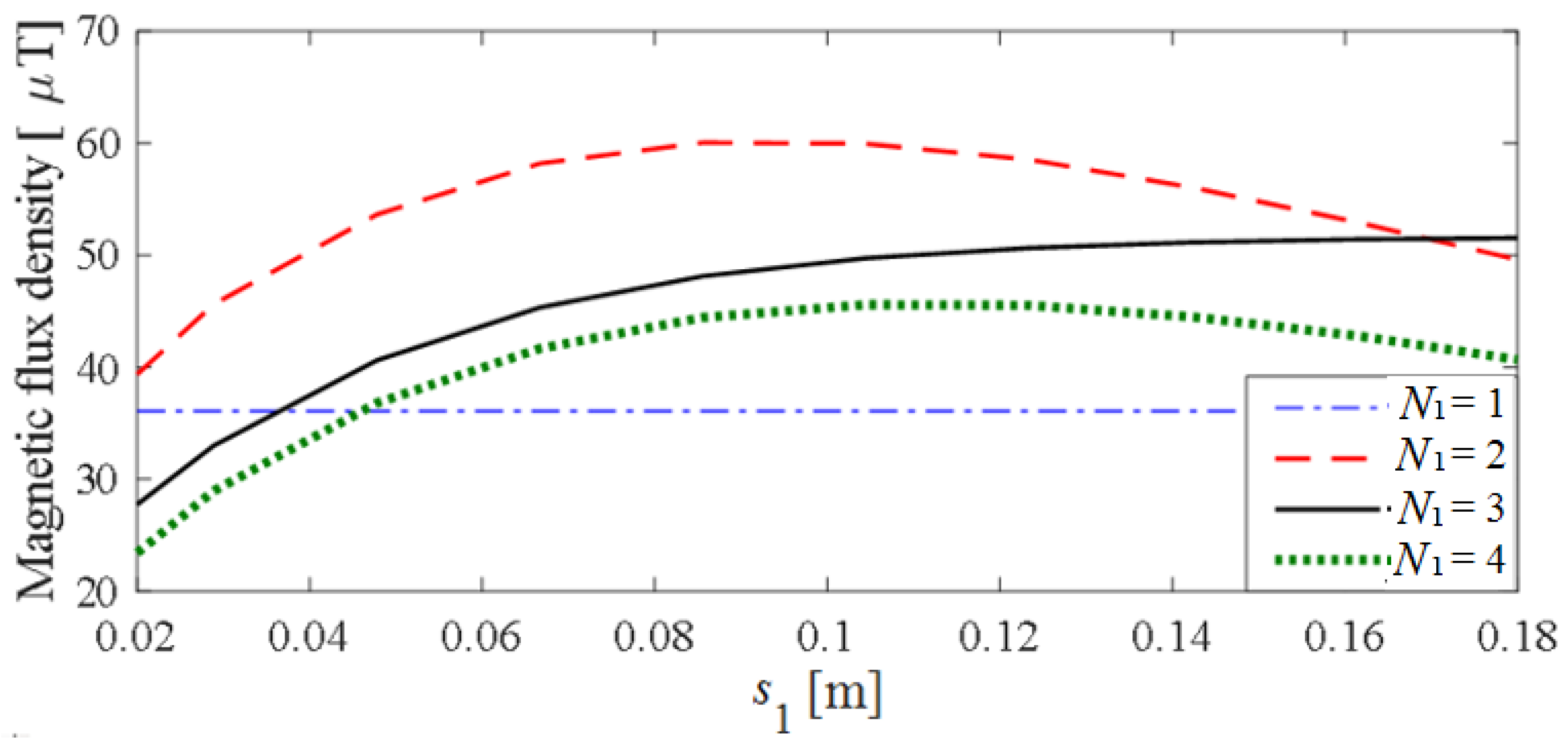
2.4. Primary-Coil Design

The goal of the primary coil design is the maximization of the time-varying magnetic field in the area where the device is implanted (i.e., attached to the heart) without exceeding the EMF safety limits [27], that at the considered frequency is mainly the specific absorption rate (SAR), since it is more critical than the internal electric field E in this type of configuration [24]. To this aim, an extensive investigation was performed to find out the primary coil configuration suitable to maximize the magnetic field in a desired area (where the LVAD is located) without exceeding the SAR inside the human tissues. The primary coil configuration is given by several planar loops that lie on the same axis and are stacked so that their planes are parallel to each other. The loops are series connected and are wound around the human trunk. This large coil configuration permits to obtain a good penetration of the magnetic field inside the human torso and it is very suitable when the implantation depth is significant. The primary coil design requires the definition of the number of turns N1 and the intra-turns spacing s1 (see Figure 5a). A simplified configuration of the trunk shown in Figure 5b was considered to find the maximum coil current I1 that allows compliance with EMF safety standards, while assuring a satisfactory magnetic field level at the receiving coil position. The torso was modeled as a multilayer elliptic cylinder with semi-major axis stmax = 180 mm, semi-minor axis stmin = 140 mm, and height Ht = 300 mm. The cylinder outer dimensions were derived from an adult male body conformation [28,29]. The multilayer domain was made of three frequency-dispersive biological tissues: the inner depth muscle and two thin external layers of fat (dfat = 3 mm) and skin (dskin = 2 mm). The dielectric properties of muscle, fat and skin at 6.78 MHz were taken from [30]. Each loop of the primary coil was elliptical (semimajor axis scmax = 185 mm, semiminor axis scmin = 145 mm) and was lain in the horizontal plane (xy plane), i.e., the elliptical cylinder axis coincided with the vertical z axis. The 3D configuration was analyzed by finite-element method (FEM) software solving magnetoquasistatic (MQS) field equations in the frequency domain. The International Commission on Non-Ionizing Radiation Protection (ICNIRP) guidelines establish a maximal admissible SAR of 2 W/kg averaged on 10 g of contiguous tissue in the human trunk at the considered frequency for the general public [27]. In our investigation, on the basis of a precautionary condition, the SAR was not averaged, and calculated as follows:
S A R = σ E 2 ρ
where E is the rms norm of the electric field; and ρ and σ are the mass density and conductivity of the tissue, respectively. Point p shown in Figure 5a, located at a distance dp = 10 cm from the internal surface of the elliptical cylinder, was assumed to be the worst-case position where the LVAD might be implanted, and it is therefore the point where the magnetic field must be maximized. The maximum distance dp = 10 cm was obtained from the body conformation of an adult male [28]. The optimal primary-coil design was found using the following two-step procedure. First, the maximum excitation in terms of magnetomotive force MMF1 = N1I1 was found by varying the number of turns N1 and the spacing s1 of the primary coil, as to comply with the SAR limit. Then, for each coil considered configuration, the magnetic-flux density B1 was derived at point p, where the LVAD is implanted. The configuration of these, providing the maximum magnetic flux density B1,max, was selected as the optimal. In the first step, the maximum MMF1 that did not produce SAR > 2 W/kg was computed for different values of N1 and s1, as shown in Figure 6. The maximum intraturn spacing and number of turns were constrained at s1 = 0.18 m and N1 = 4, respectively, while the maximum possible trunk height was set at 0.54 m. For each primary-coil considered configuration, the magnetic-flux density was calculated in point p as shown in Figure 7. The optimal coil configuration providing B1,max, has N1 = 2 and s1 = 0.08 m. In this case, the maximum admissible magnetomotive force MMF1,max = 14 At was derived from Figure 6. The maximum current flowing in the two turns with 8 cm of separation of the primary coil was I1,max = MMF1,max/N1 = 7 A. Adopting this optimal primary-coil excitation, the field distribution inside the simplified torso was calculated and the map is shown in Figure 8.

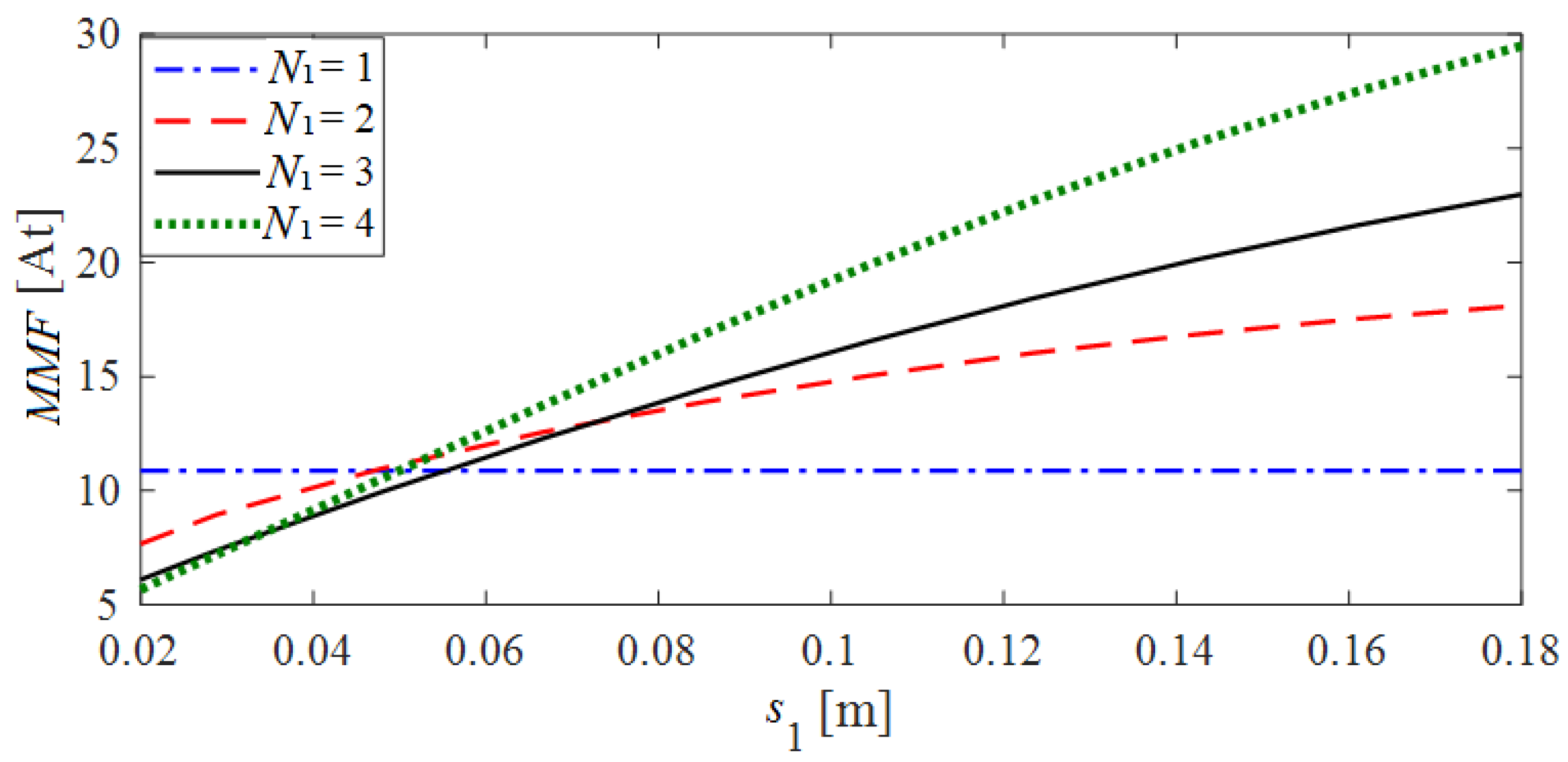
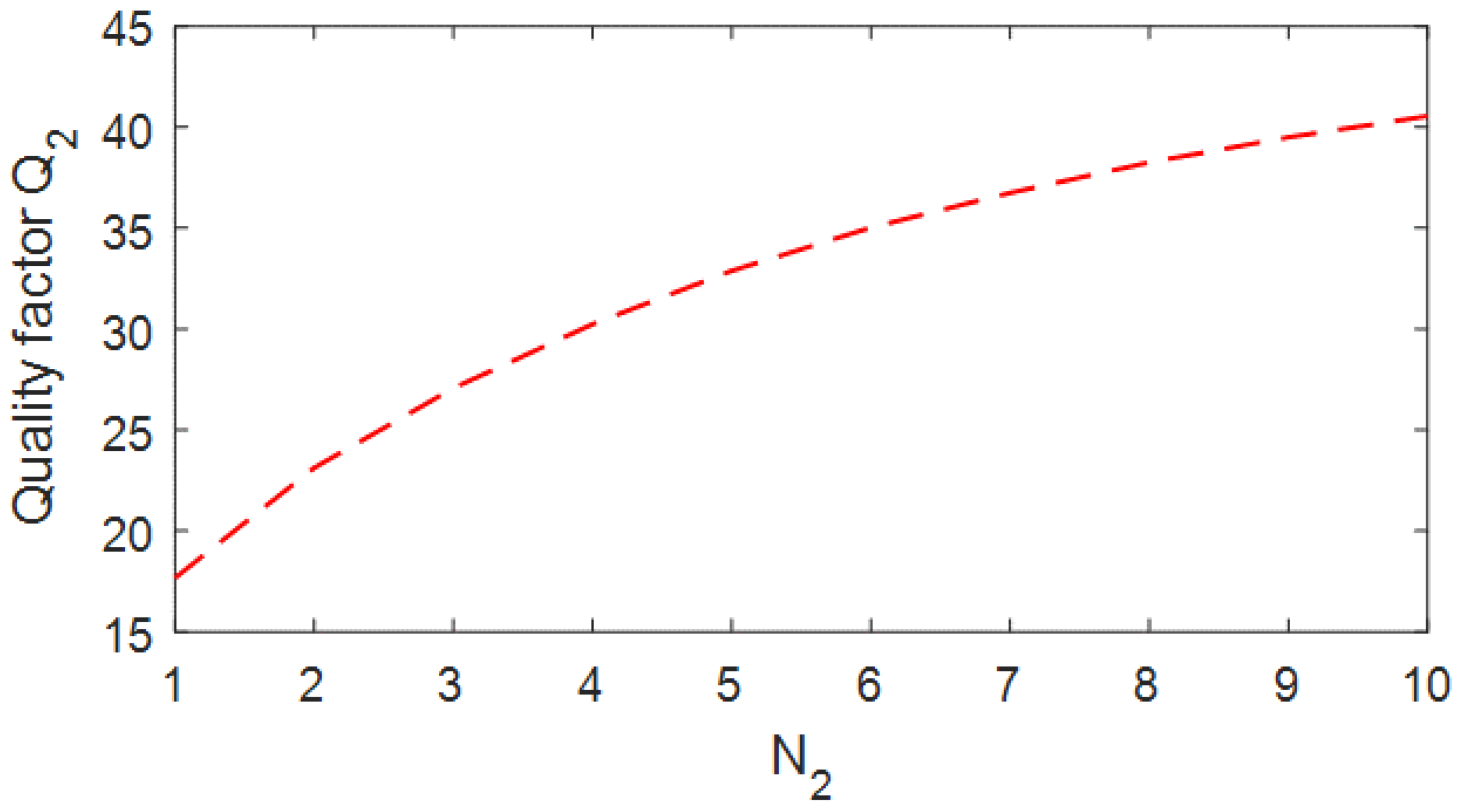
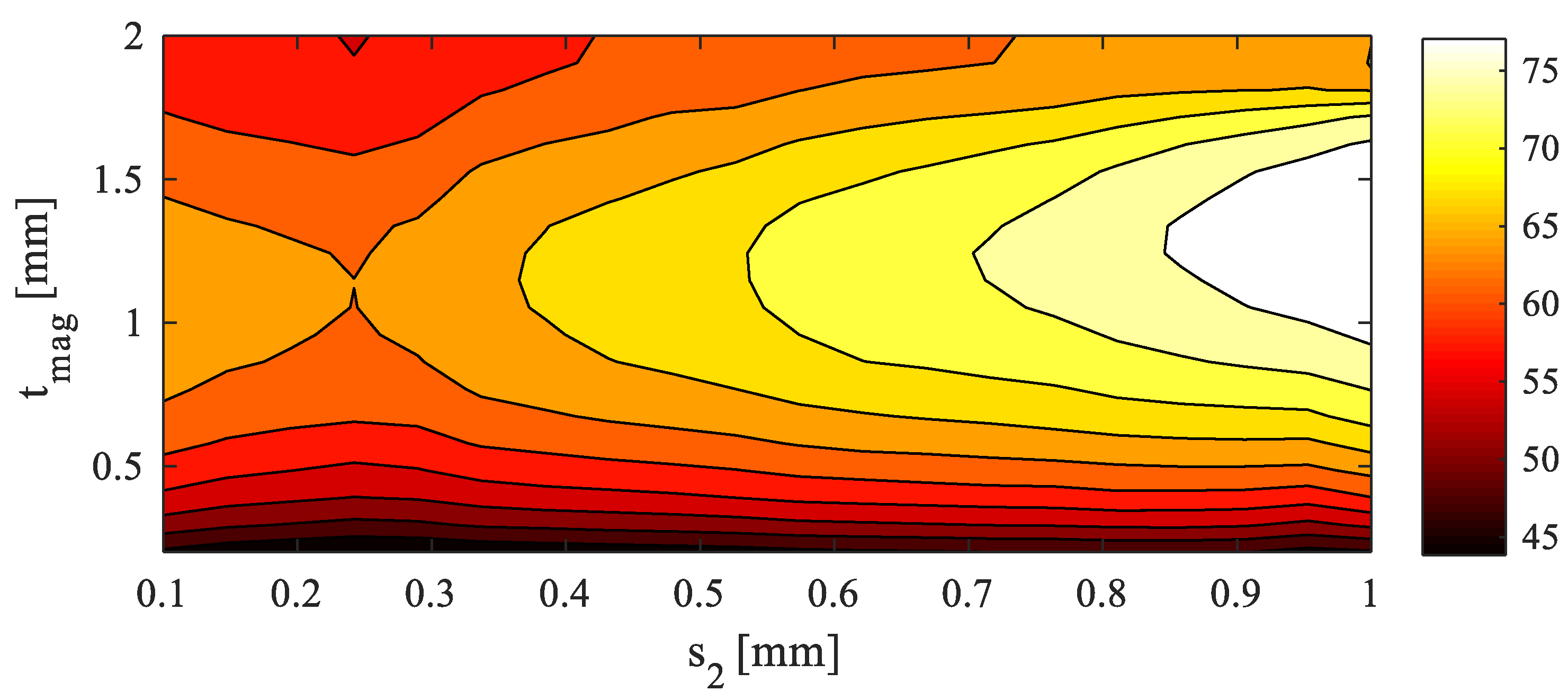
2.5. Secondary-Coil Design

The LVAD was modeled as a titanium hollow cylinder with external radius rd = 25 mm and height hd = 30 mm. The receiving coil was wound around the titanium cylinder with radius rc = 26 mm and height hc = hd = 30 mm (see Figure 9). To improve the magnetic coupling and avoid losses on the titanium housing due to eddy currents, a thin layer of ferrite with thickness tmag was mounted between housing and receiving coil. A preliminary investigation was first performed to find the optimal number of secondary-coil turns N2. Then, the electromagnetic configuration in terms of ferrite thickness tmag and intraturn spacing s2 was analyzed. The maximal reduction in ferrite is a significant challenge to reduce the weight and dimensions of the WPT system. In order to find the best configuration in terms of secondary-coil turn number N2, the optimization of the quality factor of the coil was considered. The quality factor Q2 is defined as
Q 2 = ω L 2 R 2 ,
where L2 and R2 are the secondary coil self-inductance and resistance, respectively. In this test, fixed intraturn spacing s2 = 1 mm, ferrite thickness tmag = 0.5, and coil thickness tc = 0.5 mm were considered.
For each combination of the variables, a simulation was carried out, and the coil lumped parameters were calculated by Ohm’s law. The maximal value of N2 was fixed to N2max = 10 to avoid excessive reduction in copper trace width, and consequently excessive heating. The obtained results shown in Figure 10 demonstrate that the configuration with N2 = 10 permits to obtain the maximal value of Q2.
Then, optimization was focused on the definition of intraturn spacing s2 and ferrite thickness tmag. The goal was to maximize Q2 varying s2 in the range of 0.1−1 mm, and ferrite thickness tmag in the range of 0.1−2 mm. Maximal s2 was constrained by the minimal trace width to tolerate the secondary-coil current without producing excessive heating. The coil trace width was calculated as
w c = h c s 2 ( N 2 1 ) N 2 ,
keeping total coil height hc fixed. The results of the described parametric analysis are shown in Figure 11, and clearly highlight that the optimal Q2 occurred for tmag = 1.24 mm and s2 = 1 mm.

3. Results

The electrical performance of the wireless powering system was evaluated in terms of efficiency η and transferred power PL. As a first test, the simplified circuit shown in Figure 4 was analyzed [24]. The load was assumed to be a resistor RL = 40 Ω. The coil configurations described in the previous section were adopted. According to the results of Section 2.4, the primary coil was realized with 2 series-connected loops separated by distance s1 = 80 mm, adopting 3 turns for each loop (i.e., N1 = 3 × 2 = 6) to reduce current I1. The secondary coil was designed as described in the previous section assuming that N2 = 10. The calculated self-parameters of the coils were L1 = 31.9 µH, R1 = 0.2 Ω, L2 = 10.2 µH, R2 = 5.14 Ω. The coupling factor was calculated considering three different LVAD inclination values θ, from 0° to 60°, with θ being the angle between the axis of the elliptical cylinder and the axis of the LVAD when considering it to be cylindrical. The obtained results by the MATLAB implementation of the circuit equations in terms of input and output voltages are reported in Table 1. The system maintained good electrical efficiency even for a significant inclination (θ = 60°). Then, analysis of system performance was carried out considering variation in implantation depth dp. The magnetic coupling and electrical quantities were calculated for different values of dp, from 6 to 14 cm. The obtained results, reported in Table 2, demonstrate that implantation depth dp did not significantly alter system performance.
Then, a more realistic configuration of the WPT system that included the power converters was considered and analyzed by SPICE. The equivalent SPICE circuit is shown in Figure 12. For each capacitor and inductor, an equivalent-series resistance (ESR) of 10 mΩ was considered. Excitation was performed by a high-frequency electronic inverter, while the load was modeled by a rectifier and a resistance. The high-power square signal was generated by a full-bridge MOSFET inverter. This inverter topology, which can be considered a D-class amplifier, permits a reduction in losses and very accurate control of the driving signal. Specifically, there were two main losses: conduction losses and switching losses. Conduction losses describe resistive losses during the conduction period of transistor Rds,on, while switching losses occur during the on–off and off–on transitions of the switch. At higher frequencies, such as 6.78 MHz, switching losses become dominant, significantly reducing the efficiency of the system and increasing power losses on the transistor. To this aim, gallium nitride (GaN) transistors were considered (model EPC2023) [31,32,33,34]. To drive the four GaN MOSFETs of the bridge, two independent square signals were used. On a real circuit, the signal could be easily obtained by dedicated drivers. The driving signals of MOSFETs X1 and X4 were in quadrature with the signals of MOSFETs X2 and X3.
A small dead time was introduced between the commutation of the two feeding signals to avoid short circuit during the transition phase between the upper and lower legs of the bridge. The power delivered to the load could be adjusted in several ways, but the simplest and most accurate method was based on the regulation of DC voltage before the inverter. The high-frequency signal induced on the secondary coil was converted into DC by a full-wave rectifier composed of four GaN diodes. A capacitor Cout = 10 nF was adopted to smooth the output signal. The LVAD was modeled as a simple resistor RL = 40 Ω. Lastly, system performance was calculated considering the SS compensation with C1 = 12.2 pF and C2 = 55.1 pF. Input voltage was adjusted to obtain a load power of PL = 5 W. The worst-case condition was considered adopting a device inclination θ = 60°. Currents I1 and I2 are shown in Figure 13a, while voltage Vin at the input of the WPT system and voltage Vout at the output before the rectifier are shown in Figure 13b. Overall efficiency from the DC source to the resistive load was ηtot = 65%. Power losses on the inverter and on the rectifier were 16% and 5%, respectively.

4. Conclusions

A feasibility study to power an LVAD using near-field WPT technology was presented assuming a wearable transmitting coil and a receiving coil integrated in the implanted device. The numerical investigation demonstrated that an LVAD can be successfully equipped with a WPT system to be continuously powered, assuming operational frequency of 6.78 MHz. The application of WPT technology could produce real clinical improvement, as DLIs, which are the most serious complication in patients with LVAD implanted starting one year after implantation, are strongly reduced. The optimization of the project has improved the performance of the system in terms of efficiency and power transferred in compliance with the EMF safety limits. As a main result, an average power of 5W is continuously supplied from the WPT system to the LVAD with a DC-to-DC efficiency of approximately 65% for the worst case configuration. The WPT coupling efficiency depends on implant depth and LVAD orientation, but a typical value of around 84–85% was found, while power losses on the inverter and on the rectifier were estimated to be around 16% and 5%, respectively.

Author Contributions

T.C., S.C., F.M., and M.F. conceived and planned the experiments, and carried out the simulations. All authors provided critical feedback, improved the final design, analyzed the data, and wrote the paper. All authors have read and agreed to the published version of the manuscript.

Funding

This research was funded by Projects of National Interest PRIN2017. Project title: WPT4WID: Wireless Power Transfer for Wearable and Implantable Devices, project no. 2017YJE9XK.

Conflicts of Interest

The authors declare no conflict of interest.

References

  1. Hernandez, G.A.; Nunez Breton, J.D.; Chaparro, S.V. Driveline Infection in Ventricular Assist Devices and Its Implication in the Present Era of Destination Therapy. Open J. Cardiovasc. Surg. 2019, 9. [Google Scholar] [CrossRef]
  2. Han, J.; Trumble, D. Cardiac Assist Devices: Early Concepts, Current Technologies, and Future Innovations. Bioengineering 2019, 6, 18. [Google Scholar] [CrossRef] [Green Version]
  3. Grupper, A.; Park, S.J.; Pereira, N.L.; Schettle, S.D.; Gerber, Y.; Topilsky, Y.; Edwards, B.S.; Daly, R.C.; Stulak, J.M.; Joyce, L.D.; et al. Role of ventricular assist therapy for patients with heart failure and restrictive physiology: Improving outcomes for a lethal disease. J. Hear. Lung Transplant. 2015, 34, 1042–1049. [Google Scholar] [CrossRef]
  4. Slaughter, M.S.; Rogers, J.G.; Milano, C.A.; Russell, S.D.; Conte, J.V.; Feldman, D.; Sun, B.; Tatooles, A.J.; Delgado, R.M.; Long, J.W.; et al. Advanced Heart Failure Treated with Continuous-Flow Left Ventricular Assist Device. N. Engl. J. Med. 2009, 361, 2241–2251. [Google Scholar] [CrossRef] [Green Version]
  5. Prinzing, A.; Herold, U.; Berkefeld, A.; Krane, M.; Lange, R.; Voss, B. Left ventricular assist devices—Current state and perspectives. J. Thorac. Dis. 2016, 8, E660–E666. [Google Scholar] [CrossRef] [Green Version]
  6. Amacher, R.; Ochsner, G.; Ferreira, A.; Vandenberghe, S.; Daners, M.S. A Robust Reference Signal Generator for Synchronized Ventricular Assist Devices. IEEE Trans. Biomed. Eng. 2013, 60, 2174–2183. [Google Scholar] [CrossRef] [PubMed] [Green Version]
  7. Knecht, O.; Bosshard, R.; Kolar, J.W. High-Efficiency Transcutaneous Energy Transfer for Implantable Mechanical Heart Support Systems. IEEE Trans. Power Electron. 2015, 30, 6221–6236. [Google Scholar] [CrossRef]
  8. Pavlovic, N.V.; Randell, T.; Madeira, T.; Hsu, S.; Zinoviev, R.; Abshire, M. Risk of left ventricular assist device driveline infection: A systematic literature review. Hear. Lung 2019, 48, 90–104. [Google Scholar] [CrossRef]
  9. Kim, Y.-J.; Maeng, J.; Irazoqui, P.P. Eyeglasses-powered, contact lens-like platform with high power transfer efficiency. Biomed. Microdevices 2015, 17, 1–9. [Google Scholar] [CrossRef]
  10. Manoufali, M.; Bialkowski, K.; Mohammed, B.J.; Mills, P.C.; Abbosh, A. Near-Field Inductive-Coupling Link to Power a Three-Dimensional Millimeter-Size Antenna for Brain Implantable Medical Devices. IEEE Trans. Biomed. Eng. 2017, 65, 4–14. [Google Scholar] [CrossRef] [PubMed]
  11. Jegadeesan, R.; Nag, S.; Agarwal, K.; Thakor, N.V.; Guo, Y.-X. Enabling Wireless Powering and Telemetry for Peripheral Nerve Implants. IEEE J. Biomed. Health Inform. 2015, 19, 958–970. [Google Scholar] [CrossRef]
  12. Campi, T.; Cruciani, S.; Maradei, F.; Montalto, A.; Musumeci, F.; Feliziani, M. EMI in a Cardiac Implantable Electronic Device (CIED) by the Wireless Powering of a Left Ventricular Assist Device (LVAD). IEEE Trans. Electromagn. Compat. 2021, 1–8. [Google Scholar] [CrossRef]
  13. Waters, B.H.; Sample, A.P.; Bonde, P.; Smith, J.R. Powering a Ventricular Assist Device (VAD) With the Free-Range Resonant Electrical Energy Delivery (FREE-D) System. Proc. IEEE 2011, 100, 138–149. [Google Scholar] [CrossRef]
  14. Tang, S.C.; Lun, T.L.T.; Guo, Z.; Kwok, K.-W.; McDannold, N.J. Intermediate Range Wireless Power Transfer with Segmented Coil Transmitters for Implantable Heart Pumps. IEEE Trans. Power Electron. 2017, 32, 3844–3857. [Google Scholar] [CrossRef]
  15. Pya, Y.; Maly, J.; Bekbossynova, M.; Salov, R.; Schuler, S.; Meyns, B.; Kassif, Y.; Massetti, M.; Zilbershlag, M.; Netuka, I. First human use of a wireless coplanar energy transfer coupled with a continuous-flow left ventricular assist de-vice. J. Heart Lung Transplant. 2019, 38, 339–343. [Google Scholar] [CrossRef] [PubMed] [Green Version]
  16. Knecht, O.; Kolar, J.W. Comparative evaluation of IPT resonant circuit topologies for wireless power supplies of implantable mechanical circulatory support systems. In Proceedings of the 2017 IEEE Applied Power Electronics Conference and Exposition (APEC), Tampa, FL, USA, 26–30 March 2017; pp. 3271–3278. [Google Scholar]
  17. Nagato, S.; Hijikata, W.; Shinshi, T. Evaluation of a transcutaneous energy transmission system with a flexible coil for an implantable ventricular assist device. In Proceedings of the 2017 Wireless Power Transfer Conference (WPTC), Taipei, Taiwan, 10–12 May 2017. [Google Scholar]
  18. Liu, Y.; Li, Y.; Zhang, J.; Dong, S.; Cui, C.; Zhu, C. Design a Wireless Power Transfer System with Variable Gap Applied to Left Ventricular Assist Devices. In Proceedings of the 2018 IEEE PELS Workshop on Emerging Technologies: Wireless Power Transfer (Wow), Montreal, QC, Canada, 3–7 June 2018. [Google Scholar]
  19. Cao, K.; Tang, W. Application of Wireless Power Transfer in Totally Implantable Heart Pump. In Proceedings of the 2018 IEEE Wireless Power Transfer Conference (WPTC), Montreal, QC, Canada, 3–7 June 2018; pp. 1–4. [Google Scholar]
  20. Campi, T.; Cruciani, S.; Maradei, F.; Montalto, A.; Musumeci, F.; Feliziani, M. Wireless Powering of Next-Generation Left Ventricular Assist Devices (LVADs) Without Percutaneous Cable Driveline. IEEE Trans. Microw. Theory Tech. 2020, 68, 3969–3977. [Google Scholar] [CrossRef]
  21. Farrar, D.J. The HeartMate II™ Continuous-Flow Left Ventricular Assist System. Mech. Circ. Support 2019, 70–77. [Google Scholar] [CrossRef]
  22. Jawad, A.M.; Nordin, R.; Gharghan, S.K.; Jawad, H.M.; Ismail, M. Opportunities and Challenges for Near-Field Wireless Power Transfer: A Review. Energies 2017, 10, 1022. [Google Scholar] [CrossRef]
  23. Wang, C.-S.; Covic, G.A.; Stielau, O.H. Power Transfer Capability and Bifurcation Phenomena of Loosely Coupled Inductive Power Transfer Systems. IEEE Trans. Ind. Electron. 2004, 51, 148–157. [Google Scholar] [CrossRef]
  24. Campi, T.; Cruciani, S.; De Santis, V.; Feliziani, M. EMF Safety and Thermal Aspects in a Pacemaker Equipped with a Wireless Power Transfer System Working at Low Frequency. IEEE Trans. Microw. Theory Tech. 2016, 64, 375–382. [Google Scholar] [CrossRef]
  25. COMSOL Multiphysics. Available online: www.comsol.com (accessed on 9 March 2021).
  26. Campi, T.; Cruciani, S.; De Santis, V.; Maradei, F.; Feliziani, M. Near Field Wireless Powering of Deep Medical Implants. Energies 2019, 12, 2720. [Google Scholar] [CrossRef] [Green Version]
  27. Guidelines for Limiting Exposure to Electromagnetic Fields (100 kHz to 300 GHz). Health Phys. 2020, 118, 483–524. [CrossRef]
  28. Christ, A.; Kainz, W.; Hahn, E.G.; Honegger, K.; Zefferer, M.; Neufeld, E.; Rascher, W.; Janka, R.; Bautz, W.; Chen, J.; et al. The Virtual Family—Development of surface-based anatomical models of two adults and two children for dosimetric simulations. Phys. Med. Biol. 2009, 55, N23–N38. [Google Scholar] [CrossRef] [PubMed]
  29. Gosselin, M.-C.; Neufeld, E.; Moser, H.; Huber, E.; Farcito, S.; Gerber, L.; Jedensjö, M.; Hilber, I.; Di Gennaro, F.; Lloyd, B.; et al. Development of a new generation of high-resolution anatomical models for medical device evaluation: The Virtual Population 3.0. Phys. Med. Biol. 2014, 59, 5287–5303. [Google Scholar] [CrossRef]
  30. Hasgall, P.A.; di Gennaro, F.; Baumgartner, C.; Neufeld, E.; Lloyd, B.; Gosselin, M.C.; Payne, D.; Klingenböck, A.; Kuster, N. IT’IS Database for Thermal and Electromagnetic Parameters of Biological Tissues. Available online: www.itis.swiss/database (accessed on 9 March 2021).
  31. Shevchenko, V.; Pakhaliuk, B.; Husev, O.; Veligorskyi, O.; Stepins, D.; Strzelecki, R. Feasibility Study GaN Transistors Application in the Novel Split-Coils Inductive Power Transfer System with T-Type Inverter. Energies 2020, 13, 4535. [Google Scholar] [CrossRef]
  32. Ma, C.-T.; Gu, Z.-H. Review of GaN HEMT Applications in Power Converters over 500 W. Electronics 2019, 8, 1401. [Google Scholar] [CrossRef] [Green Version]
  33. Rodríguez-Benítez, O.M.; Ponce-Silva, M.; Aquí-Tapia, J.A.; Claudio-Sánchez, A.; Vela-Váldes, L.G.; Lozoya-Ponce, R.E.; Cortés-García, C. Comparative Performance and Assessment Study of a Current-Fed DC-DC Resonant Converter Combining Si, SiC, and GaN-Based Power Semiconductor Devices. Machines 2020, 9, 1982. [Google Scholar] [CrossRef]
  34. Rahmani, F.; Niknejad, P.; Agarwal, T.; Barzegaran, M. Gallium Nitride Inverter Design with Compatible Snubber Circuits for Implementing Wireless Charging of Electric Vehicle Batteries. Machines 2020, 8, 56. [Google Scholar] [CrossRef]
Figure 1. Configuration of a traditional powered left ventricular assist device (LVAD) using (a) percutaneous driveline cable and (b) with integrated wireless power system. The angle θ is the inclination of the LVAD with respect to the axis of the primary coil.
Electronics 10 00874 g001
Figure 2. Mock circulatory loop used to characterize LVAD power requirements.
Electronics 10 00874 g002
Figure 3. Measured transient hydraulic and electrical quantities (pressure, current, voltage, power).
Electronics 10 00874 g003
Figure 4. Equivalent circuit of wireless-power-transfer (WPT) system with series–series (SS) compensation topology.
Electronics 10 00874 g004
Figure 5. (a) Primary-coil geometry for N1 = 3. (b) Simplified torso configuration with primary coil.
Electronics 10 00874 g005
Figure 6. MMF1 versus intraturn spacing s1 that produces maximum admissible SAR = 2 W/kg inside human torso.
Electronics 10 00874 g006
Figure 7. Magnetic-flux density B1 at point p versus intraturn spacing s1, produced by maximum MMF1 that, for each configuration, is compliant with SAR limit of 2 W/kg inside human torso.
Electronics 10 00874 g007
Figure 8. Magnetic-field distribution inside trunk for N1 = 2, s1= 0.08 m and MMF1 = 14 At.
Electronics 10 00874 g008
Figure 9. 3D model of the LVAD with secondary coil (a) and 2D axially symmetric secondary coil configuration (b).
Electronics 10 00874 g009
Figure 10. Quality factor Q2 of the receiving coil versus N2, adopting fixed values of intraturn spacing s2 = 1 mm, ferrite thickness tmag = 0.5 and coil thickness tc = 0.5 mm.
Electronics 10 00874 g010
Figure 11. Map of the calculated quality factor Q2.
Electronics 10 00874 g011
Figure 12. Equivalent circuit with electronic components.
Electronics 10 00874 g012
Figure 13. Waveforms of (a) input and output voltages and (b) coil currents.
Electronics 10 00874 g013aElectronics 10 00874 g013b
Table 1. Electrical quantities vs. device inclination (θ angle).
θ°kI1 (A)I2 (A)V1 (V)V2 (V)η
00.0370.470.3512.314.20.86
300.0320.550.3510.714.10.85
600.0190.950.356.614.10.79
Table 2. Electrical quantities vs. implantation depth dp for θ = 30°.
dp (cm) kI1 (A)I2 (A)V1 (V)V2 (V)η
60.0390.460.3512.714.10.86
80.0350.510.3511.514.10.85
100.0320.550.3510.714.10.85
120.0260.690.358.714.10.83
140.0220.810.357.514.10.81
Publisher’s Note: MDPI stays neutral with regard to jurisdictional claims in published maps and institutional affiliations.

