Article

A New Grid-Connected Constant Frequency Three-Phase Induction Generator System under Unbalanced-Voltage Conditions

by
Mohammadreza Moradian
1,2,*,
Jafar Soltani
3,
Gholam Reza Arab Markadeh
4,
Hossein Shahinzadeh
5 and
Yassine Amirat
6,*
1
Department of Electrical Engineering, Najafabad Branch, Islamic Azad University, Najafabad 85141-43131, Iran
2
Smart Microgrid Research Center, Najafabad Branch, Islamic Azad University, Najafabad 85141-43131, Iran
3
Faculty of Electrical and Computer Engineering, Isfahan University of Technology, Isfahan 84156-83111, Iran
4
Department of Engineering, Shahrekord University, Shahrekord 88186-34141, Iran
5
Department of Electrical Engineering, Amirkabir University of Technology (Tehran Polytechnic), Tehran 15916-34311, Iran
6
L@bISEN, ISEN Yncréa Ouest, Brest Campus, 20, Rue Cuirassé Bretagne, 29200 Brest, France
*
Authors to whom correspondence should be addressed.
Electronics 2021, 10(8), 938; https://doi.org/10.3390/electronics10080938
Submission received: 12 March 2021 / Revised: 8 April 2021 / Accepted: 13 April 2021 / Published: 14 April 2021

Abstract

:
This paper presents a new constant frequency, direct grid-connected wind-based induction generator system (IGS). The proposed system includes a six-phase cage rotor with two separate three-phase balanced stator windings and a three-phase SV-PWM inverter which is used as a STATCOM. The first stator winding is connected to the STATCOM and is used to excite the machine. The main frequency of the STATCOM is considered to be constant and equal to the main grid frequency. In the second stator winding, the frequency of the induced emf is equal to the constant frequency, so the generator output frequency is independent of the load power demand and its prime mover speed. The second stator winding is directly connected to the main grid without an intermediate back-to-back converter. In order to regulate the IGS output active and reactive power components, a sliding mode control (SMC) is designed. Assuming unbalanced three-phase voltages for the main grid, a second SMC is developed to remove the machine output’s negative sequence currents. Moreover, a conventional PI controller is used to force the average exchanging active power between the machine and STATCOM to zero. This PI controller generates the reference value of the rotor angular speed. An adjustable speed pitch angle-controlled wind turbine is used as the IGS’s prime mover. The effectiveness and capability of the proposed control scheme have been supported by the simulation results.

1. Introduction

The use of wind energy by the electrical power generation industry has significantly enhanced in the past two decades. Today, use of wind energy conversion systems (WECSs) for distributed generation, especially in remote areas with weak networks, has grown significantly [1]. During the development of wind-based power generation systems, a new type of generator system has been introduced which supports the improvement of the overall system performance and ensures a higher cost-effectiveness of the system. Nowadays, the wound-rotor doubly fed induction generators (DFIGs), the brush-less DFIGs (BDFIGs), the cage-rotor induction generators (CRIGs), equipped with full-rate back-to-back (BTB) converters, and the permanent magnet synchronous generators (PMSGs), equipped with full-rate BTB converters, are the most widely used generators in WECSs [2,3]. The CRIGs have some advantages such as low price, simpler structures, high ruggedness, less depreciation, and more reliability compared with the others [4,5]. The most important weakness of this generator is its poor output voltage and frequency regulation characteristics, which are influenced by the generator prime mover angular speed varying as well as by the generator load power demand changing. In addition, the magnetizing reactive power of CRIGs has to be supplied by a reliable source [6]. These problems can be directly solved by using a full-rate intermediate BTB converter. However, such BTB converters are expensive, especially in high-power rating systems. Although some solutions were proposed in the literature to solve the mentioned problems, there is a need to introduce a CRIG-based system that produces an intrinsically constant frequency, independent of the prime mover speed and the load power demand. Thus, the converted energy supplied the local load or the main grid can be achieved without a BTB converter.
All of the above-mentioned generators can be operated as standalones or as a grid-connected generation systems. These systems employ different controllers in order to increase the energy conversion efficiency, enhance the power quality, and solve the system’s particular problems [7,8,9,10,11,12,13,14]. Lack of symmetry in the three-phase voltages is one of the common phenomena in the remote areas with weak networks due to the presence of single-phase or unbalanced three-phase loads [15,16,17]. In such conditions, the negative sequence currents will be flown in the generator windings and the network. These extra currents not only bring about power losses in the network, but they also lead to the formation of power and torque pulsations, the machine overheating, and reductions in efficiency and lifetime [18,19]. Therefore, some research works have been carried out to remove the negative sequence extra current and some more control targets in different types of generators [20,21,22,23,24,25,26,27,28].
In Reference [24], based on the instantaneous power theory, a control scheme in an unbalanced microgrid is reported for a doubly fed induction generator. The rotor-side converter was controlled for mitigating the torque and reactive power pulsation, while the grid-side converter was controlled for partial compensation of unbalanced stator voltage. In Reference [25], a combination of a voltage-modulated direct power control with an extra shunt compensator for the DFIG systems is proposed under unbalanced grid conditions. The method can provide a regulating property of the negative sequence output currents. Moreover, the control method guarantees a satisfactory steady-state performance by providing symmetrical stator currents and suppresses the ripples in both active and reactive powers under unbalanced grid conditions. A resonant-based back-stepping direct power control scheme is reported in [26] for a DFIG under both balanced and unbalanced grid conditions. This control method tried to achieve three control targets:
  • to obtain constant active and reactive powers without a ripple;
  • to obtain constant electromagnetic torque and reactive power without a ripple;
  • to obtain a symmetrical and sinusoidal stator current.
In Reference [27], a negative sequence compensation control scheme is studied for the magnetizing current in a DFIG. The reference value for the current is modified to have a negative sequence compensating component for the magnetizing current. To minimize the ripple in power and electromagnetic torque, the rotor-side converter is controlled to remove the pulsations in magnetizing current. Additionally, the grid-side converter is employed to maintain unity power factor and a constant DC-link voltage. It was shown that choosing the magnetizing current as a single control target enabled simultaneous reductions in pulsations in torque, power, and DC-link voltage and also minimized unbalance in currents. A stator/rotor current vector control of a doubly fed induction generator connected to the unbalanced three-phase voltage power grid is presented in [28]. The selected control targets were considered as fixed electromagnetic torque and symmetrical stator or rotor current. These vector control schemes did not use a separate negative sequence calculator and controller. On the other hand, signal filtration is employed to achieve the positive sequence components of variables.
A new CRIG-based WECS with a fixed output frequency, independent of the generator shaft speed and load power demand, is introduced in [29,30]. This induction generator system (IGS) is composed of a six-phase CRIG with a stator consisting of two three-phase balanced winding sets along with an SV-PWM inverter operating as a STATCOM. The first three-phase stator winding set, called exciting winding (EW), is connected to the STATCOM and used to excite the generator. The second stator winding set, used as the generator outlet and called power winding (PW), is directly connected to the local load. The control system based on conventional PI controllers [29] or sliding mode controllers [30] is used to regulate the three-phase generator output and DC-link voltage in symmetrical conditions.
This proposed generator is used as a remote WECS under the unbalanced three-phase local load condition [31]. The conventional PI controllers were employed for three different control targets. The first one is to regulate the load positive sequence voltage while simultaneously removing the load negative sequence voltage. In the second and third control targets, the positive sequence voltage is regulated while simultaneously removing the load either negative-sequence-current or active power double-frequency-component.
Although the induction generator system presented in [29,30,31] can be used either as an isolated or a grid-connected distributed generation system, only the isolated mode of operation is reported either in balanced or unbalanced three-phase local loads. Therefore, the main aim of this paper is to evaluate the performance assessment of this new induction generation system in the grid-connected mode of operation.
In this paper, the recently discussed SCIG is used in a grid-connected asymmetrical condition. In order to regulate the IGS output’s active and reactive power components, a sliding mode control (SMC) was designed. This controller determines the STATCOM positive sequence reference voltages. Upon assumption of network having unbalanced three-phase voltages, a second SMC was developed to remove the generator output’s negative sequence currents injected into the network. In addition, a PI controller was employed to force the average active power, exchanged between the STATCOM and the EW machine, to zero by determining the rotor reference speed. An adjustable speed wind turbine with a pitch angle controller was used as the prime mover of the generator. The proposed IGS is simulated by a C++ computer program under either symmetrical or asymmetrical three-phase grid voltage conditions. The simulation results verify the effectiveness and capabilities of the proposed system.

2. Induction Generator System Model

Figure 1 shows the overview of the proposed IGS. Based on this figure, the IGS modeling can be described in the following:

2.1. Machine Model

The space vector of a general variable for a three-phase machine in a stationary reference frame is defined by [32]:
f ¯ i s = 2 3 ( f a i + a f b i + a 2 f c i ) = f d i s + j f q i s , a = e j 2 π 3
where fi refers to voltage, current, and linkage flux; superscript s denotes the stationary reference frame, and subscript i is referred stator (i = s) or rotor (i = r) variables.
The space vector f ¯ i s in a synchronous reference frame can be defined as [32]:
f ¯ i e = f d i e + j f q i e = f ¯ i s e j ω e t
where superscript e denotes the synchronous reference frame and machine synchronous electrical angular speed is defined as ωe.
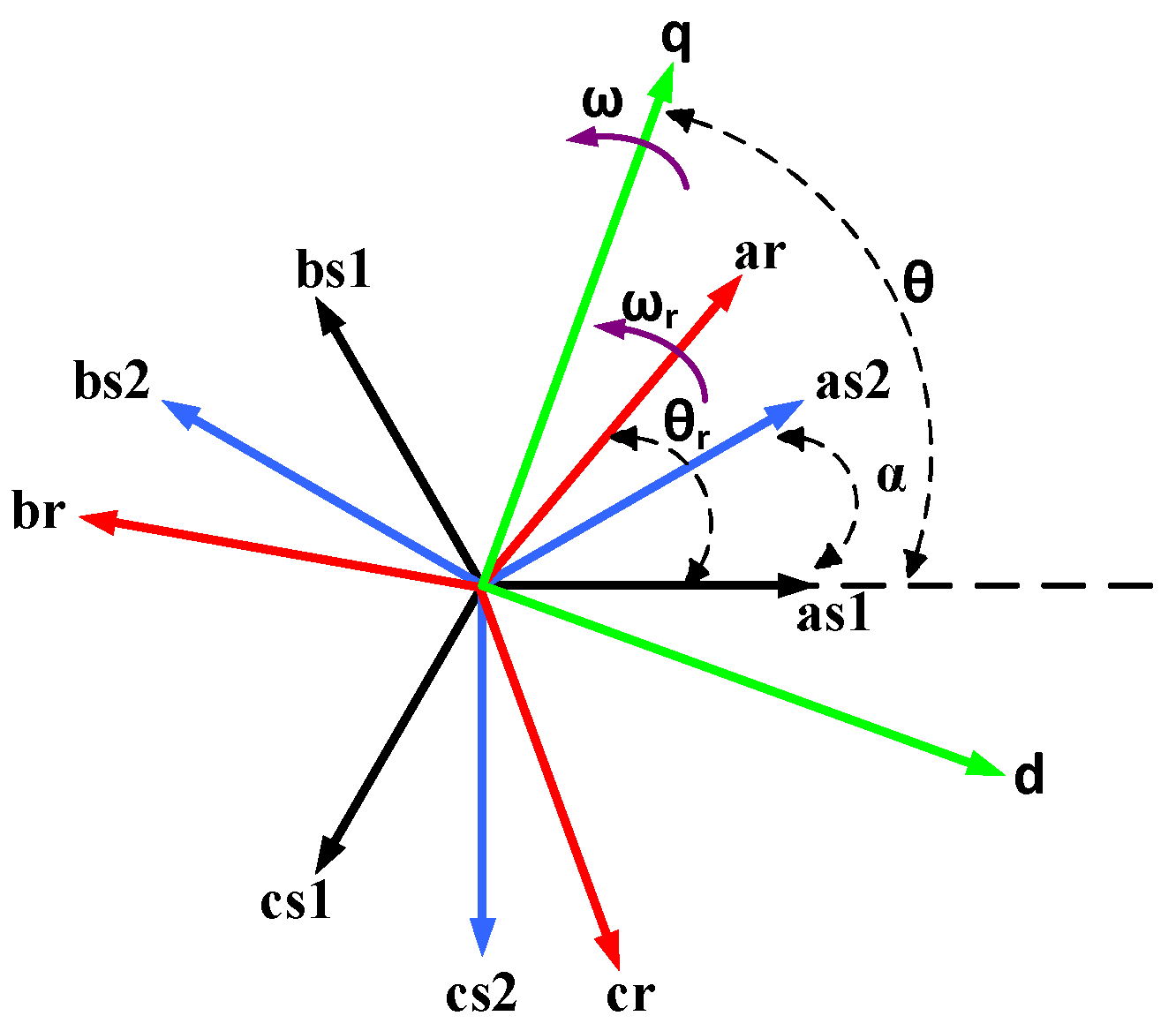
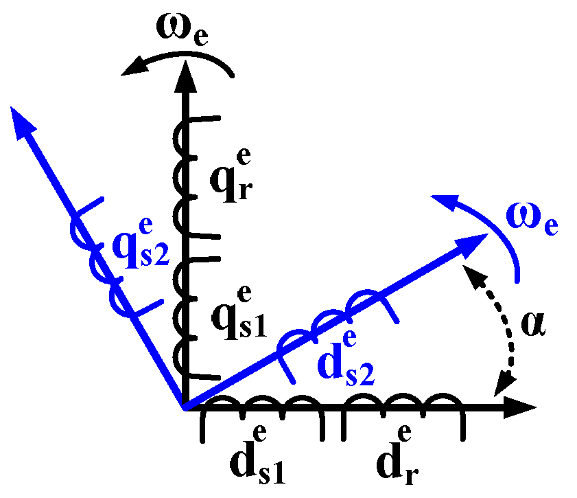
As Figure 2 shows, the two three-phase stator windings are located in the α electrical degree spatial phase related to each other. Based on Figure 3, the IGS voltage space vector equations in (de,qe) synchronous reference frame are described by [29]:
v ¯ s 1 e = λ ¯ ˙ s 1 e + R s 1 i ¯ s 1 e + j ω e λ ¯ s 1 e
v ¯ s 2 e = λ ¯ ˙ s 2 e + R s 2 i ¯ s 2 e + j ω e λ ¯ s 2 e
v ¯ r e = λ ¯ ˙ r e + R r i ¯ r e + j ( ω e ω r ) λ ¯ r e
with
λ ¯ s 1 e = L s 1 i ¯ s 1 e + L m i ¯ s 2 e e j α + L m i ¯ r e
λ ¯ s 2 e = L m i ¯ s 1 e e j α + L s 2 i ¯ s 2 e + L m i ¯ r e e j α
λ ¯ r e = L m i ¯ s 1 e + L m i ¯ s 2 e e j α + L r i ¯ r e
{ L s 1 = L l s 1 + L m L s 2 = L l s 2 + L m L r = L l r + L m
where subscripts s1, s2, and r refer to the EW, PW, and rotor variables; electrical angular speed is defined as ωr; v ¯ s 1 e , v ¯ s 2 e , v ¯ r e are voltages of the machine in space vectors; λ ¯ s 1 e , λ ¯ s 2 e , λ ¯ r e are machine linkage fluxes in vector space; i ¯ s 1 e , i ¯ s 2 e , i ¯ r e are currents of the machine in space vectors; and Rs1, Rs2, Rr are the stator and rotor winding resistances. In addition, Lm is spatial magnetizing inductance, Lls1, Lls2, Llr are leakage inductances of machine windings, and Ls1, Ls2, Lr are spatial machine self-inductances. It is necessary to mention that EW and rotor parameters are on the PW side.
The PW generator is assumed to be connected to the main grid via an (Rc,Lc) interface impedance. For this case, the grid connection space vector equation in (de,qe) reference frame is described by:
v ¯ s 2 e = v ¯ G e R c i ¯ s 2 e L c i ¯ ˙ s 2 e j L c ω e i ¯ s 2 e
where v ¯ G e is the space vector of three-phase grid voltages. Additionally, the mechanical equation of the machine is:
J ω ˙ m = T t u r b T e B ω m
with
T e = 3 2 ( λ d s 2 e i q s 2 e - λ q s 2 e i d s 2 e )
where Te is electromagnetic torque of the generator; Tturb is prime mover torque of the generator; ωm is the mechanical angular speed of the machine; J is the rotor moment of inertia; B is the friction coefficient.

2.2. Generator State Space Model

The state-space equation of the machine can be defined in matrix form as follows:
X ˙ = F ( X ) + G ( X ) U
with
X = [ i q s 1 e i d s 1 e λ q s 1 e λ d s 1 e i q s 2 e i d s 2 e ω r ] T
U = [ v q s 1 e v d s 1 e T t u r b ] T
F ( X ) = [ f 1 f 2 f 3 f 4 f 5 f 6 f 7 ] T
G ( X ) = [ a 11 0 1 0 a 21 a 22 0 0 a 11 0 1 a 22 a 21 0 0 0 0 0 0 0 1 J ] T
where fi functions and aij coefficients are given in the paper’s Appendix A.

2.3. Wind Turbine Model

The mechanical power developed by a wind turbine is given by [33]:
P w = 1 2 ρ π r 2 C p ( λ , β ) V w i n d 3
where the turbine output power is shown as Pw; air density is defined as ρ; the radius of the turbine blades is shown as r; Vwind is the wind speed; CP(λ,β) is the power coefficient of the wind turbine; β is the pitch angle of turbine blades; λ is the tip speed ratio defined as:
λ = r ω r t V w i n d
where ωrt is the angular speed of the turbine shaft. The power coefficient of the wind turbine is given as [33]:
C p = ( 0.44 0.0167 β ) sin ( π ( λ 3 ) 15 0.3 β ) 0.00184 β ( λ 3 )
Additionally, the wind speed turbulences are considered as:
V w i n d = V a v [ 1 + 0.02 ( sin ( 2 π t 5 ) + sin ( 6 π t 5 ) + sin ( 20 π t 5 ) ) ]
where Vav is the average amount of wind speed.

3. Sliding Mode Controllers

3.1. Positive Sequence SMC

An SMC was designed to regulate the generator output active and reactive power components in the following way:
Y + = [ y 1 + y 2 + ] T = [ P G + Q G + ] T
U + = [ u 1 + u 2 + ] T = [ v q s 1 r e f e + v d s 1 r e f e + ] T
where subscript G refers to the grid and + refers to positive sequence components; v q s 1 r e f e + and v d s 1 r e f e + are the STATCOM positive sequence reference voltages.
The following error signals were used:
{ e P G + ( t ) = P G + P G r e f + e Q G + ( t ) = Q G + Q G r e f +
where P G r e f + and Q G r e f + are the reference values for the grid absorbed powers.
Aligning the de-axis of the reference frame along the main grid positive sequence voltage position, the qe-axis of the grid voltage positive sequence, v q G + will be zero and SMC outputs could be formulated as:
{ P G + = 3 2 ( v d G e + i d G e + + v q G e + i q G e + ) = + 3 2 v d G e + i d G e + Q G + = 3 2 ( v d G e + i q G e + v q G e + i d G e + ) = 3 2 v d G e + i q G e +
with
{ i q G e + = i q s 2 e + i d G e + = i d s 2 e +
Choosing the following sliding mode switching surfaces:
S 12 = [ S 1 S 2 ] = [ e P G + ( t ) + k 1 p e P G + ( t ) d t e Q G + ( t ) + k 1 q e Q G + ( t ) d t ]
where the k1p and k1q are positive and constant coefficients. In the sliding manifold and slide along the surface, the system can be defined as [34]:
S 12 = S ˙ 12 = 0
Combining Equations (24)–(28) and (13) results in:
S ˙ 12 = [ S ˙ 1 S ˙ 2 ] = [ H 1 H 2 ] + [ D 11 D 12 D 12 D 11 ] [ v q s 1 e + v d s 1 e + ] = H 12 + D U +
with
{ D 11 = 3 2 a 22 v d G e + D 12 = 3 2 a 21 v d G e + H 1 = 3 2 v d G e + ( a 23 v d s 2 e + a 25 i q s 1 e + + a 24 i d s 1 e + a 27 λ q s 1 e + + a 26 λ d s 1 e + a 29 i q s 2 e + + a 28 i d s 2 e + ) + k 1 p e P G + H 2 = 3 2 v d G e + ( a 23 v q s 2 e + + a 24 i q s 1 e + + a 25 i d s 1 e + + a 26 λ q s 1 e + + a 27 λ d s 1 e + + a 28 i q s 2 e + + a 29 i d s 2 e + ) + k 1 q e Q G +
From Equations (28) and (29), the equivalent SMC control effort is obtained as:
U e c + = [ u e c 1 + u e c 2 + ] = [ D 11 D 12 D 12 D 11 ] 1 [ H 1 H 2 ]
where U e c + is the vector of the STATCOM positive sequence equivalent reference voltages.
Equation (31) can be changed to the following equation to guarantee the sliding mode reaching phase [34]:
[ u 1 + u 2 + ] = [ D 11 D 12 D 12 D 11 ] 1 { [ H 1 H 2 ] + [ K 2 p 0 0 K 2 q ] [ s a t ( S 1 ) s a t ( S 2 ) ] } = D - 1 [ H 12 + K 2 p q s a t ( S 12 ) ]
with
K 2 p q = [ k 2 p 0 0 k 2 q ] , s a t ( S 12 ) = [ s a t ( S 1 ) s a t ( S 2 ) ] , s a t ( S i ) = { 1 S i > λ i S i λ i | S i | λ i 1 S i < λ i
where k2p and k2q are the sliding mode positive control gains and λi is the sliding mode saturation bandwidth.
We used the following Lyapunov function:
V = 1 2 S 12 T S 12 = 1 2 S 1 2 + 1 2 S 2 2 0
A derivative of V gives:
V ˙ = 1 2 S ˙ 12 T S 12 + 1 2 S 12 T S ˙ 12 = S 1 S ˙ 1 + S 2 S ˙ 2
Combining (29), (32), and (35), V ˙ is reduced to:
V ˙ = S 12 T S ˙ 12 = S 12 T K 2 p q s a t ( S 12 ) = K 2 p S 1 s a t ( S 1 ) K 2 q S 2 s a t ( S 2 ) 0
Equation (36) shows that V ˙ is a negative definite function and as a result, the designed SMC is asymptotically stable.

3.2. Negative Sequence SMC

Assuming a main grid with unbalanced three-phase voltages, an SMC was designed to eliminate the generator output’s negative sequence currents. We introduced the following input–output vectors:
Y - = [ y 1 y 2 ] T = [ i q G e i d G e ] T
U - = [ u 1 u 2 ] T = [ v q s 1 r e f e v d s 1 r e f e ] T
Using the following error signals:
{ e i q ( t ) = i q G e 0 e i d ( t ) = i d G e 0
where i q G e and i d G e are the negative sequence currents, injected into the grid with zero references. Sliding mode switching surfaces were introduced as:
S 34 = [ S 3 S 4 ] = [ e i q ( t ) + k 1 i q e i q ( t ) d t e i d ( t ) + k 1 i d e i d ( t ) d t ]
where k1iq and k1id are the SMC positive constants. The system in the sliding manifold and slide along the surface can be defined as [34]:
S 34 = S ˙ 34 = 0
Combining (13), (26) and (39)–(41) gives:
S ˙ 34 = [ S ˙ 3 S ˙ 4 ] = [ H 3 H 4 ] + [ a 21 a 22 a 22 a 21 ] [ v q s 1 e v d s 1 e ] = H 34 + A U
with
H 3 = a 23 v q s 2 e + a 24 i q s 1 e + a 25 i d s 1 e + a 26 λ q s 1 e + a 27 λ d s 1 e + a 28 i q s 2 e + a 29 i d s 2 e + k 1 i q e i q H 4 = a 23 v d s 2 e a 25 i q s 1 e + a 24 i d s 1 e a 27 λ q s 1 e + a 26 λ d s 1 e a 29 i q s 2 e + a 28 i d s 2 e + k 1 i d e i d
From (41) and (42), the equivalent SMC control effort can be obtained as:
U e c - = [ u e c 1 u e c 2 ] = [ a 21 a 22 a 22 a 21 ] 1 [ H 3 H 4 ]
where U e c - is the vector of STATCOM negative sequence equivalent reference voltages.
Using Equation (44), the following control action was used to ensure the sliding mode reaches the phase [34]:
[ u 1 u 2 ] = [ a 21 a 22 a 22 a 21 ] 1 { [ H 3 H 4 ] + [ k 2 i q 0 0 k 2 i d ] [ s a t ( S 3 ) s a t ( S 4 ) ] } = A - 1 [ H 34 + K 2 i s a t ( S 34 ) ]
with
K 2 i = [ k 2 i q 0 0 k 2 i d ] , s a t ( S 34 ) = [ s a t ( S 3 ) s a t ( S 4 ) ]
where k2iq and k2id are the sliding mode positive control gains. Nominating the following Lyapunov function:
V = 1 2 S 34 T S 34 = 1 2 S 3 2 + 1 2 S 4 2 0
Taking the derivative of V results in:
V ˙ = 1 2 S ˙ 34 T S 34 + 1 2 S 34 T S ˙ 34 = S 3 S ˙ 3 + S 4 S ˙ 4
Combining (40), (42), (45), and (48), V ˙ is reduced to:
V ˙ = S 34 T S ˙ 34 = S 34 T K 2 i s a t ( S 344 ) = k 2 i q S 3 s a t ( S 3 ) k 2 i d S 4 s a t ( S 4 ) 0
It can be said that in Equation (49) V ˙ is a definite function and positive, and therefore the designed SMC is asymptotically stable.

4. Simulation and Results

Considering the 1.8 kW six-phase CRIG shown in Table 1 with a regulated speed wind turbine based on a pitch angle controller [34] and also the mentioned theory in the previous sections, a C++ computer program, using the static fourth-order Runge–Kutta method, was developed to solve nonlinear differential equations of the machine. The simulation was implemented for both balanced and unbalanced three-phase voltages of the main grid.

4.1. Balanced Grid Results

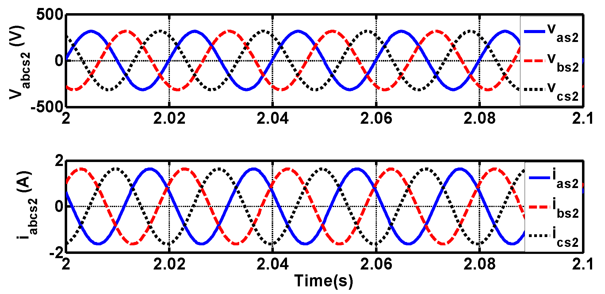
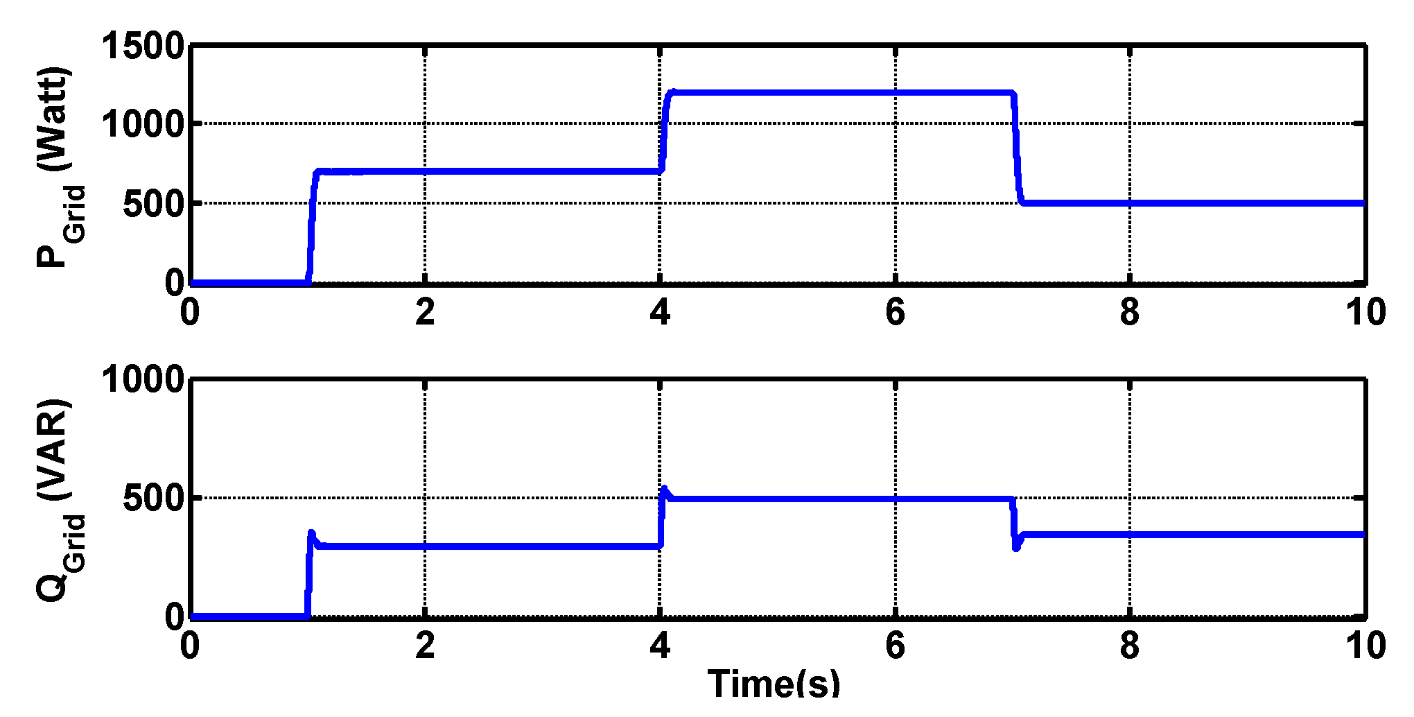
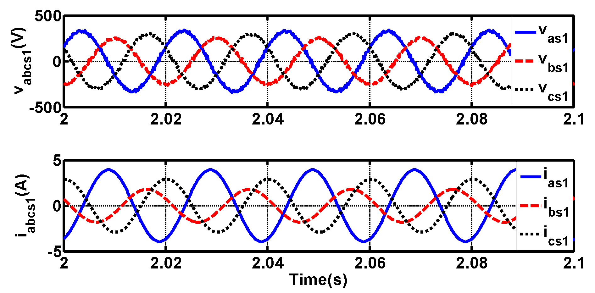
The voltage build-up process occurred in a standalone no-load condition during the first 1 s and the generator connected to the main grid at t = 1 s. The main grid’s balanced three-phase voltages are shown in Figure 4. Considering the active and reactive power reference values as (P+G-ref = 700 watt and Q+G-ref = 300 var) at t = 1 s, the steady-state generator output voltage and current waveforms obtained for this test are shown in Figure 5. Additionally, STATCOM waveforms such as voltage and current are shown in Figure 6. It should be noted that a low-pass L-C filter with a cut-off frequency of 1 kHz was utilized to connect the three-phase STATCOM to the EW. This filter is capable of filtering out the STATCOM high-order harmonics and as a result, nearly a pure sinusoidal rotating flux density wave was obtained.
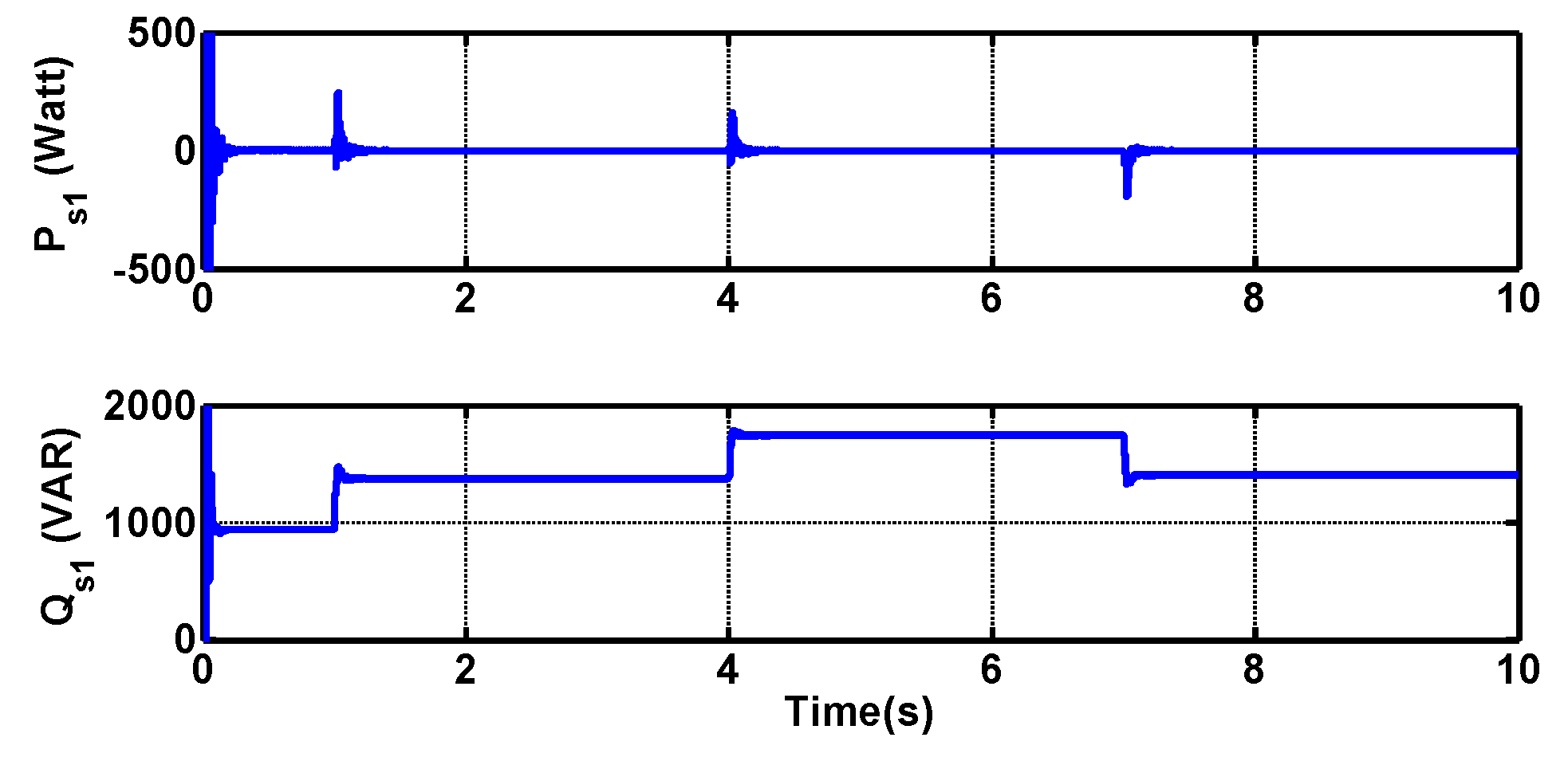
Assuming the same condition as mentioned for the first test, reference values of power demands were stepped up to (P+G-ref = 1200 watt and Q+G-ref = 500 var) at t = 4 s, and finally stepped down to (P+G-ref = 500 watt and Q+G-ref = 350 var) at t = 7 s. The simulation results obtained for these tests are shown in Figure 7, Figure 8, Figure 9 and Figure 10.
Figure 7 shows the STATCOM output active and reactive power waveforms. It can be seen that the exchanged active power between EW and STATCOM is zero. Figure 8 represents the active and reactive powers absorbed by the grid. Additionally, Figure 9 shows the wind linear speed and wind turbine pitch angle variations. Moreover, the rotor electrical angular speed is shown in Figure 10.

4.2. Unbalanced Grid Results

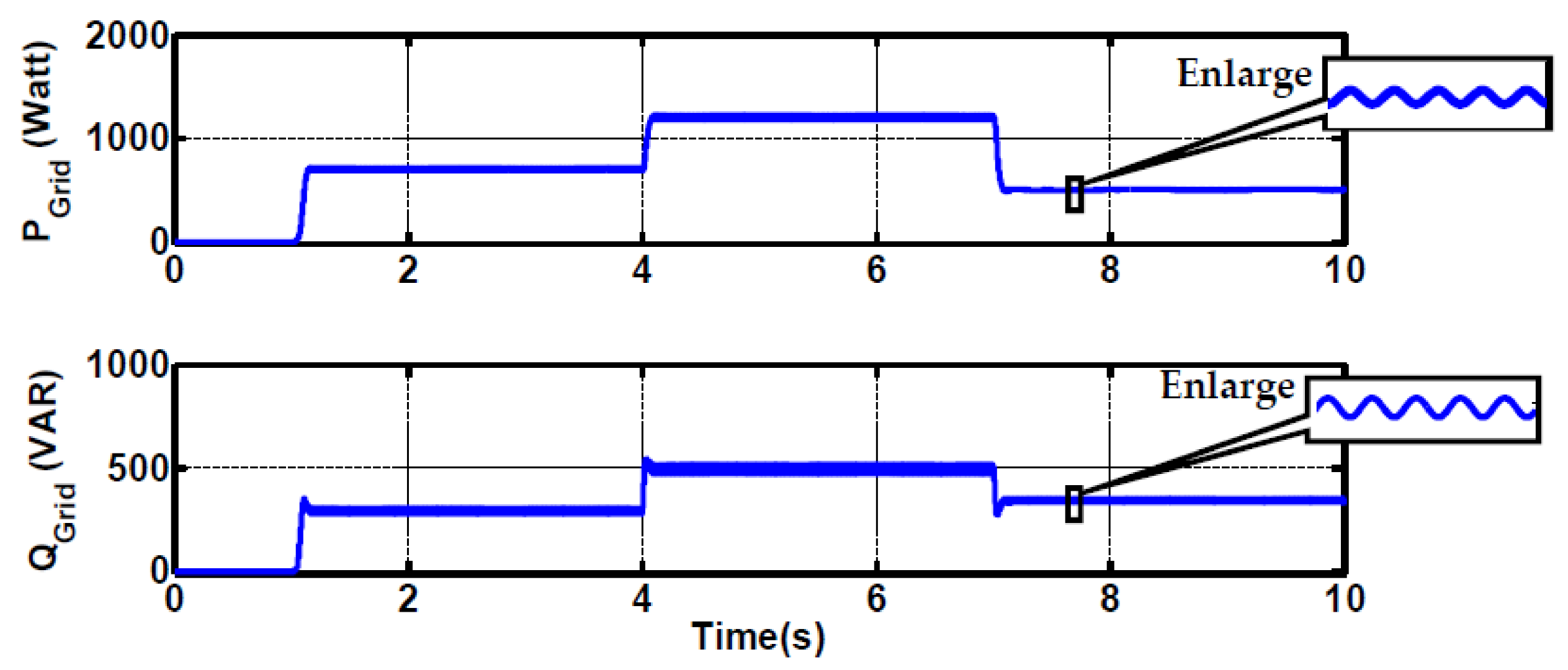
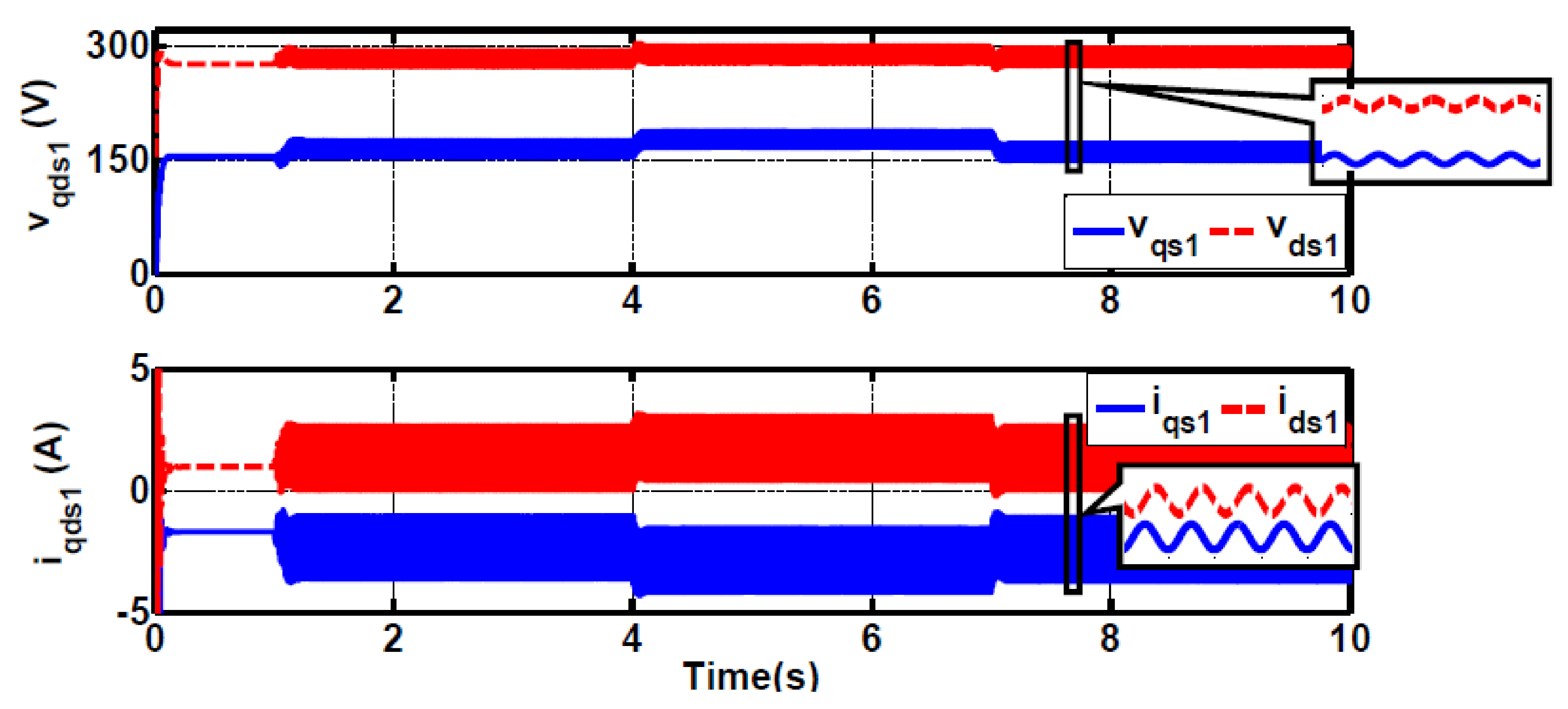
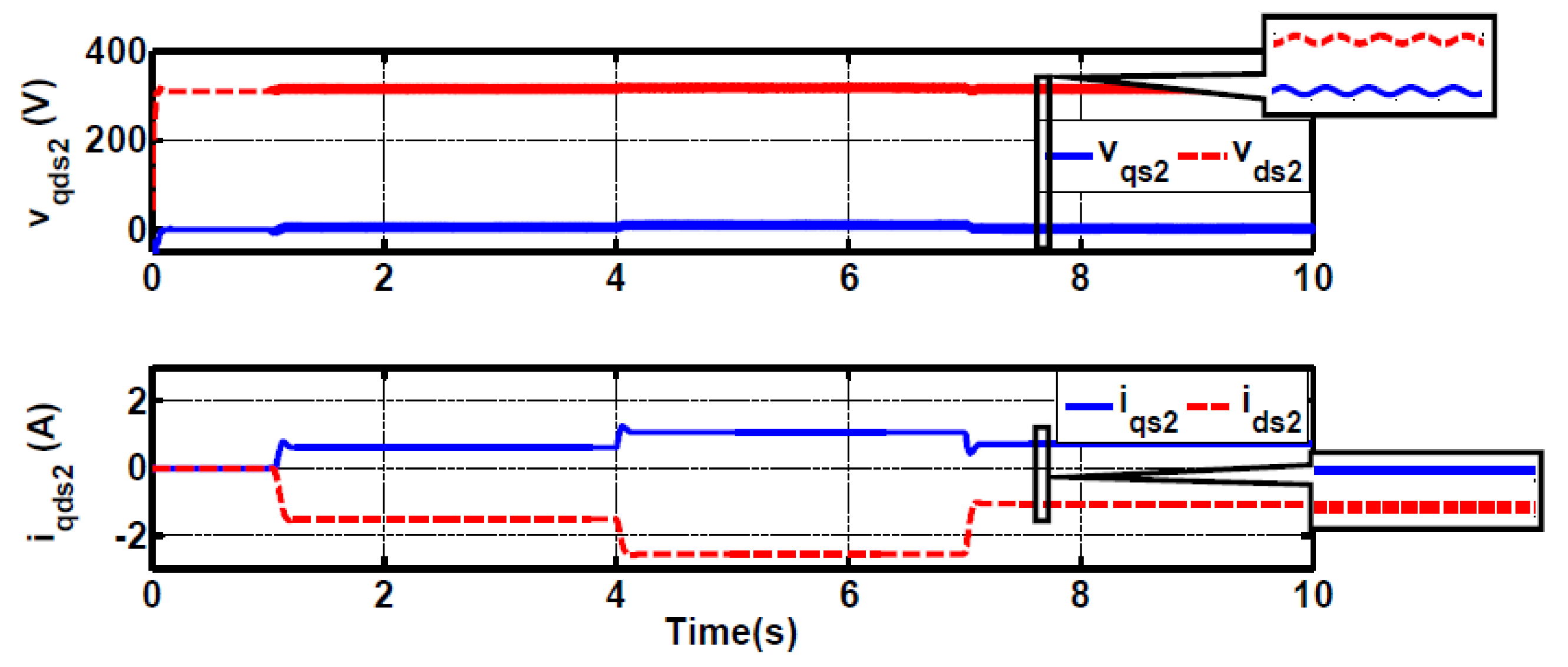
Considering unbalanced three-phase voltages for the grid as shown in Figure 11 and assuming the same conditions as mentioned in balanced grid mode, the simulation results are shown in Figure 12, Figure 13, Figure 14, Figure 15, Figure 16 and Figure 17.
As is shown in Figure 14 and Figure 15, the active and reactive powers obtained for generator windings are composed of a DC part and a double frequency sinusoidal waveform. The double frequency oscillations resulted from the interaction between voltage negative sequence and current positive sequence components.
Additionally, the two-axis components of EW and PW voltage and current waveforms in the synchronous reference frame are demonstrated in Figure 16 and Figure 17. As can be seen, only the generator output current components in (de,qe) are purely DC. The other variable waveforms consisted of a DC value superimposed with a double frequency (100 Hz) sinusoidal term. It is worth mentioning that the DC term refers to the positive sequence and the double frequency part refers to the negative sequence of corresponding variables.
As can be seen in the results, the sliding mode chattering is significantly low. This is due to the use of a narrow bandwidth sliding mode saturation layer and a low-pass filter in software.

5. Conclusion

In this paper, a new three-phase IGS with a constant frequency, independent of rotor speed, has been proposed as a distributed generation in local networks or the main one. This IGS employs a six-phase CRIG with two separate three-phase stator windings. The first stator winding set is connected to an SV-PWM inverter, operating as a STATCOM, to excite the machine. The second stator winding set is directly connected to the main grid. The proposed IGS is capable of regulating the generator output active and reactive powers. Moreover, upon assumption of network having unbalanced three-phase voltages, the proposed IGS is capable of removing the generator output’s negative sequence currents. An SMC has been designed to regulate the generator output’s active and reactive powers and a second SMC has been developed to eliminate the negative sequence of PW currents. Additionally, in order to force the STATCOM to only feed the reactive power to the machine, a conventional PI controller was employed to generate the rotor angular speed reference value. An adjustable speed pitch angle-controlled wind turbine was used as the IGS’s prime mover. The effectiveness and capability of the proposed IGS in balanced and unbalanced network voltage conditions have been verified by the simulation results.

Author Contributions

Conceptualization, M.M., J.S., G.R.A.M. and H.S.; Software, M.M., J.S., G.R.A.M. and H.S.; Supervision, M.M., J.S., G.R.A.M., H.S. and Y.A.; Validation, M.M., J.S., G.R.A.M., H.S. and Y.A.; Writing—Original draft, M.M., J.S., G.R.A.M., H.S. and Y.A.; Writing—Review and editing, M.M., J.S., G.R.A.M., H.S. and Y.A. All authors have read and agreed to the published version of the manuscript.

Funding

This research received no external funding.

Conflicts of Interest

The authors declare no conflict of interest.

Appendix A

IGS model functions and coefficients:
f 1 = a 12 v q s 2 e + a 13 v d s 2 e + a 14 i q s 1 e + a 15 i d s 1 e + a 16 λ q s 1 e + a 17 λ d s 1 e + a 18 i q s 2 e + a 19 i d s 2 e
f 2 = a 13 v q s 2 e + a 12 v d s 2 e a 15 i q s 1 e + a 14 i d s 1 e a 17 λ q s 1 e + a 16 λ d s 1 e a 19 i q s 2 e + a 18 i d s 2 e
f 3 = R s 1 i q s 1 e ω e λ d s 1 e
f 4 = R s 1 i d s 1 e + ω e λ q s 1 e
f 5 = a 23 v q s 2 e + a 24 i q s 1 e + a 25 i d s 1 e + a 26 λ q s 1 e + a 27 λ d s 1 e + a 28 i q s 2 e + a 29 i d s 2 e f 6 = a 23 v d s 2 e a 25 i q s 1 e + a 24 i d s 1 e a 27 λ q s 1 e + a 26 λ d s 1 e a 29 i q s 2 e + a 28 i d s 2 e f 7 = [ 3 2 ( λ d s 2 e i q s 2 e λ q s 2 e i d s 2 e ) B ω r ] / J
a 11 = ( L l r L m + L l s 2 L r ) / [ L m ( L l s 1 L l r G 3 L l s 2 ) ]
a 12 = L l r cos ( α ) / ( G 3 L l s 2 L l s 1 L l r )
a 13 = L l r sin ( α ) / ( G 3 L l s 2 L l s 1 L l r )
a 14 = [ R s 1 L l r L m + L l s 2 ( R s 1 L r + R r L s 1 ) ] / [ L m ( G 3 L l s 2 L l s 1 L l r ) ]
a 15 = [ ω e L l s 1 L l r G 3 ( ω e ω r ) L l s 2 ] / ( G 3 L l s 2 L l s 1 L l r )
a 16 = R r L l s 2 / [ L m ( G 3 L l s 2 L l s 1 L l r ) ]
a 17 = ω r L r L l s 2 / [ L m ( G 3 L l s 2 L l s 1 L l r ) ]
a 18 = [ ( R r cos ( α ) ( ω e ω r ) L l r sin ( α ) ) L l s 2 ( R s 2 cos ( α ) ω e L l s 2 sin ( α ) ) L l r ] / ( G 3 L l s 2 L l s 1 L l r )
a 19 = [ ( R r sin ( α ) + ( ω e ω r ) L l r cos ( α ) ) L l s 2 ( R s 2 sin ( α ) + ω e L l s 2 cos ( α ) ) L l r ] / ( G 3 L l s 2 L l s 1 L l r )
a 21 = cos ( α ) ( G 3 L m + L l s 1 L r ) / [ L m ( G 3 L l s 2 L l s 1 L l r ) ]
a 22 = sin ( α ) [ G 3 L m + L l s 1 L r ] / [ L m ( G 3 L l s 2 L l s 1 L l r ) ]
a 23 = G 3 / ( G 3 L l s 2 L l s 1 L l r )
a 24 = [ R s 1 L r L l s 1 cos ( α ) ( ω e ω r ) G 3 L l s 1 L m sin ( α ) + R r L s 1 L l s 1 cos ( α ) + ( R s 1 cos ( α ) + ω e L l s 1 sin ( α ) ) L m G 3 ] / [ L m ( G 3 L l s 2 L l s 1 L l r ) ]
a 25 = [ ( R s 1 L l s 1 L r sin ( α ) + ( ω e ω r ) G 3 L l s 1 L m cos ( α ) + R r L l s 1 L s 1 sin ( α ) + ( R s 1 sin ( α ) ω e L l s 1 cos ( α ) ) L m G 3 ] / [ L m ( G 3 L l s 2 L l s 1 L l r ) ]
a 26 = L l s 1 [ R r cos ( α ) + ω r L r sin ( α ) ] / [ L m ( G 3 L l s 2 L l s 1 L l r ) ]
a 27 = L l s 1 [ R r sin ( α ) + ω r L r cos ( α ) ] / [ L m ( G 3 L l s 2 L l s 1 L l r ) ]
a 28 = ( R r L l s 1 G 3 R s 2 ) / ( G 3 L l s 2 L l s 1 L l r )
a 29 = [ ( ω e ω r ) L l s 1 L l r G 3 ω e L l s 2 ] / ( G 3 L l s 2 L l s 1 L l r )
G 30 = ( L m 2 L s 1 L r ) / L m

References

  1. Wafaa, M.B.; Dessaint, L.A. Approach to Dynamic Voltage Stability Analysis for DFIG Wind Parks Integration. IET Renew. Power Gener. 2017, 12, 190–197. [Google Scholar] [CrossRef]
  2. Carrasco, J.M.; Franquelo, L.G.; Bialasiewicz, J.T.; Galván, E.; PortilloGuisado, R.C.; Prats, M.M.; Moreno-Alfonso, N. Power-Electronic Systems for the Grid Integration of Renewable Energy Sources: A Survey. IEEE Trans. On Ind. Electron. 2006, 53, 1002–1016. [Google Scholar] [CrossRef]
  3. Wang, R.; Xie, Y.; Zhang, H.; Li, C.; Li, W.; Terzija, V. Dynamic Power Flow Algorithm Considering Frequency Regulation of Wind Power Generators. IET Renew. Power Gener. 2017, 11, 1218–1225. [Google Scholar] [CrossRef]
  4. Silva, E.O.; Vanço, W.E.; Guimarães, G.C. Capacitor Bank Sizing for Squirrel Cage Induction Generators Operating in Distributed Systems. IEEE Access 2020, 8, 27507–27515. [Google Scholar] [CrossRef]
  5. Chinmaya, K.A.; Singh, G.K. Modeling and Experimental Analysis of Grid-Connected Six-Phase Induction Generator for Variable Speed Wind Energy Conversion System. Electr. Power Syst. Res. 2019, 166, 151–162. [Google Scholar] [CrossRef]
  6. Zhang, F.; Yu, S.; Wang, Y.; Jin, S.; Jovanovic, M.G. Design and Performance Comparisons of Brushless Doubly Fed Generators with Different Rotor Structures. IEEE Trans. On Ind. Electron. 2018, 66, 631–640. [Google Scholar] [CrossRef] [Green Version]
  7. Kusiak, A.; Zhang, Z.; Li, M. Optimization of Wind Turbine Performance with Data-Driven Models. IEEE Trans. On Sustain. Energy 2010, 1, 66–76. [Google Scholar] [CrossRef]
  8. Singh, B.; Kasal, G.K. Independent Voltage and Frequency Controller for a Parallel Operated Isolated Three-Phase Asynchronous Generators. Eur. Trans. On Electr. Power 2009, 19, 839–853. [Google Scholar] [CrossRef]
  9. Leon, A.E.; Farias, M.F.; Battaiotto, P.E.; Solsona, J.A.; Valla, M.I. Control Strategy of a DVR to Improve Stability in Wind Farms Using Squirrel-Cage Induction Generators. IEEE Trans. on Power Syst. 2010, 26, 1609–1617. [Google Scholar] [CrossRef]
  10. Alharbi, M.; Alfaris, F.E.; Bhattacharya, S. A Novel Current Control Strategy for a Back-to-Back HVDC Applications Under Unbalanced Operation Conditions. In Proceedings of the 2017 IEEE Energy Conversion Congress and Exposition (ECCE), Cincinnati, Ohio, USA, 1–5 October 2017; pp. 1263–1269. [Google Scholar] [CrossRef]
  11. Arya, S.R.; Niwas, R.; Bhalla, K.K.; Singh, B.; Chandra, A.; Al-Haddad, K. Power Quality Improvement in Isolated Distributed Power Generating System Using DSTATCOM. IEEE Trans. On Ind. Appl. 2015, 51, 4766–4774. [Google Scholar] [CrossRef]
  12. Satpathy, A.S.; Kastha, D.; Kishore, K. Control of a STATCOM-Assisted Self-Excited Induction Generator-Based WECS Feeding Non-Linear Three-Phase and Single-Phase Loads. IET Power Electron. 2018, 12, 829–839. [Google Scholar] [CrossRef]
  13. Peng, Y.; Li, Y.; Lee, K.Y.; Tan, Y.; Cao, Y.; Wen, M.; Li, W. Coordinated Control Strategy of PMSG and Cascaded H-Bridge STATCOM in Dispersed Wind Farm for Suppressing Unbalanced Grid Voltage. IEEE Trans. on Sustain. Energy 2020, 12, 349–359. [Google Scholar] [CrossRef]
  14. Chaudhary, S.K.; Teodorescu, R.; Rodriguez, P.; Kjaer, P.C.; Gole, A.M. Negative Sequence Current Control in Wind Power Plants with VSC-HVDC Connection. IEEE Trans. Sustain. Energy 2012, 3, 535–544. [Google Scholar] [CrossRef]
  15. Koutiva, X.I.; Vrionis, T.D.; Vovos, N.A.; Giannakopoulos, G.B. Optimal Integration of an Offshore Wind Farm to a Weak AC Grid. IEEE Trans. on Power Deliv. 2006, 21, 987–994. [Google Scholar] [CrossRef]
  16. Hongbo, Q.; Yanqi, W.; Ran, Y. The Influence of Unbalance Load on the Electromagnetic and Temperature Field of High-Speed Permanent Magnet Generator. IEEE Trans. Magn. 2018, 55, 1–4. [Google Scholar] [CrossRef]
  17. Mishra, R.; Saha, T.K. Control of SCIG Based Distributed Power Generation Scheme Supplying Nonlinear and Unbalanced Load. In Proceedings of the 2018 IEEE International Conference on Power Electronics, Drives and Energy Systems (PEDES), Chennai, India, 18–21 December 2018; pp. 1–6. [Google Scholar] [CrossRef]
  18. Yao, J.; Li, H.; Chen, Z.; Xia, X.; Chen, X.; Li, Q.; Liao, Y. Enhanced Control of a DFIG-Based Wind-Power Generation System with Series Grid-Side Converter Under Unbalanced Grid Voltage Conditions. IEEE Trans. Power Electron. 2012, 28, 3167–3181. [Google Scholar] [CrossRef]
  19. Iqbal, A.; Singh, G.K. Modeling and Stability Analysis of Three-and Six-Phase Asymmetrical Grid-Connected Induction Generator. Electr. Eng. 2020, 1–13. [Google Scholar] [CrossRef]
  20. Li, Z.; Xie, Z.; Wang, Z.; Weng, H.; Wang, L. A New Protection Strategy Based on Negative Sequence Current Coordinated Control on the Generator Extremity. IEEE Access 2020, 8, 135329–135338. [Google Scholar] [CrossRef]
  21. Zeng, X.; Yao, J.; Chen, Z.; Hu, W.; Chen, Z.; Zhou, T. Co-Ordinated Control Strategy for Hybrid Wind Farms with PMSG and FSIG Under Unbalanced Grid Voltage Condition. IEEE Trans. Sustain. Energy 2016, 7, 1100–1110. [Google Scholar] [CrossRef] [Green Version]
  22. Xu, L.; Cheng, M.; Wei, X.; Yan, X.; Zeng, Y. Dual Synchronous Rotating Frame Current Control of Brushless DoublyFed Induction Generator under Unbalanced Network. IEEE Trans. Power Electron 2020. [Google Scholar] [CrossRef]
  23. Eltamaly, A.M.; Al-Saud, M.S.; Abo-Khalil, A.G. Dynamic Control of a DFIG Wind Power Generation System to Mitigate Unbalanced Grid Voltage. IEEE Access 2020, 8, 39091–39103. [Google Scholar] [CrossRef]
  24. Rezaei, E.; Ebrahimi, M.; Tabesh, A. Control of DFIG Wind Power Generators in Unbalanced Microgrids Based on Instantaneous Power Theory. IEEE Trans. Smart Grid 2016, 8, 2278–2286. [Google Scholar] [CrossRef]
  25. Gao, S.; Zhao, H.; Gui, Y.; Zhou, D.; Terzija, V.; Blaabjerg, F. A Novel Direct Power Control for DFIG with Parallel Compensator under Unbalanced Grid Condition. IEEE Trans. Ind. Electron. 2020. [Google Scholar] [CrossRef]
  26. Wang, X.; Sun, D.; Zhu, Z.Q. Resonant-Based Backstepping Direct Power Control Strategy for DFIG Under Both Balanced and Unbalanced Grid Conditions. IEEE Trans. Ind. Appl. 2017, 53, 4821–4830. [Google Scholar] [CrossRef]
  27. Rani, M.A.A.; Nagamani, C.; Ilango, G.S. Compensation of Magnetizing Current for Enhanced Operation of DFIG Under Grid Unbalance. IEEE Trans. Power Electron. 2016, 32, 5214–5226. [Google Scholar] [CrossRef]
  28. Iwanski, G.; Łuszczyk, T.; Pura, P.; Szypulski, M. Indirect Torque and Stator Reactive Power Control of Doubly Fed Induction Machine Connected to Unbalanced Power Network. IEEE Trans. Energy Convers. 2016, 31, 1202–1211. [Google Scholar] [CrossRef]
  29. Moradian, M.; Soltani, J. A Novel Control Method for an Isolated Three-Phase Induction Generator with Constant Frequency and Adjustable Output Voltage. Int. Trans. Electr. Energy Syst. 2016, 26, 2074–2086. [Google Scholar] [CrossRef]
  30. Moradian, M.; Soltani, J. Sliding Mode Control of a New Wind-Based Isolated Three-Phase Induction Generator System with Constant Frequency and Adjustable Output Voltage. J. Power Electron. 2016, 16, 675–684. [Google Scholar] [CrossRef] [Green Version]
  31. Moradian, M.; Soltani, J. An Isolated Three-Phase Induction Generator System with Dual Stator Winding Sets Under Unbalanced Load Condition. IEEE Trans. Energy Convers. 2016, 31, 531–539. [Google Scholar] [CrossRef]
  32. Vas, P. Electrical Machines and Drives: A Space-Vector Theory Approach; Clarendon Press: Oxford, UK, 1992; Volume 1. [Google Scholar]
  33. Barakati, S.M.; Kazerani, M.; Aplevich, J.D. Maximum Power Tracking Control for a Wind Turbine System Including a Matrix Converter. IEEE Trans. Energy Convers. 2009, 24, 705–713. [Google Scholar] [CrossRef]
  34. Slotine, J.J.E.; Li, W. Applied Nonlinear Control; Prentice Hall: Englewood Cliffs, NJ, USA, 1991; Volume 199. [Google Scholar]
Figure 1. The overall configuration of the system.
Electronics 10 00938 g001
Figure 2. Generator phasor diagram.
Electronics 10 00938 g002
Figure 3. Representation of generator windings in (de,qe) reference frame.
Electronics 10 00938 g003
Figure 4. The grid’s three-phase balanced voltages.
Electronics 10 00938 g004
Figure 5. The PW three-phase output voltages and currents.
Electronics 10 00938 g005
Figure 6. The EWthree-phase voltages and currents.
Electronics 10 00938 g006
Figure 7. EW input powers.
Electronics 10 00938 g007
Figure 8. The powers delivered to the grid.
Electronics 10 00938 g008
Figure 9. (a) Pitch angle of wind turbine blades; (b) the wind speed.
Electronics 10 00938 g009
Figure 10. Rotor angular speed in electrical rad/s.
Electronics 10 00938 g010
Figure 11. The grid’s unbalanced three-phase voltages.
Electronics 10 00938 g011
Figure 12. The EW unbalanced three-phase voltages and currents.
Electronics 10 00938 g012
Figure 13. The PW unbalanced three-phase output voltages and currents.
Electronics 10 00938 g013
Figure 14. The EW machine’s input powers.
Electronics 10 00938 g014
Figure 15. Powers delivered to the grid.
Electronics 10 00938 g015
Figure 16. (de,qe) components of excitation voltages and currents.
Electronics 10 00938 g016
Figure 17. (de,qe) components of generator output voltages and currents.
Electronics 10 00938 g017
Table 1. Generator parameters.
Number of Pole PairsPole1
FrequencyFn50 Hz
PowerPn1.8 kW
Both stator line voltagesVL380 V
Both stator line currentsIL3.5 A
Stator EW resistanceRs12.4 Ω
Stator PW resistanceRs22.4 Ω
Rotor resistanceRr4.1 Ω
Stator EW leakage inductanceLls111 mH
Stator PW leakage inductanceLls211 mH
Rotor leakage inductanceLlr11 mH
Magnetization inductanceLm374 mH
EW and PW spatial phase differenceα30°e
Inertia momentumJ0.038 Kgm2
Publisher’s Note: MDPI stays neutral with regard to jurisdictional claims in published maps and institutional affiliations.