Article

LQR-Based Adaptive Virtual Inertia for Grid Integration of Wind Energy Conversion System Based on Synchronverter Model

by
Walter Gil-González
1,
Oscar Danilo Montoya
2,3,
Andrés Escobar-Mejía
4 and
Jesús C. Hernández
5,*
1
Facultad de Ingeniería, Institución Universitaria Pascual Bravo, Campus Robledo, Medellín 050036, Colombia
2
Facultad de Ingeniería, Universidad Distrital Francisco José de Caldas, Bogotá D.C. 11021, Colombia
3
Laboratorio Inteligente de Energía, Universidad Tecnológica de Bolívar, Cartagena 131001, Colombia
4
Facultad de Ingeniería, Universidad Tecnológica de Pereira, Pereira 660003, Colombia
5
Department of Electrical Engineering, University of Jaén, Campus Lagunillas s/n, Edificio A3, 23071 Jaén, Spain
*
Author to whom correspondence should be addressed.
Electronics 2021, 10(9), 1022; https://doi.org/10.3390/electronics10091022
Submission received: 6 March 2021 / Revised: 13 April 2021 / Accepted: 22 April 2021 / Published: 25 April 2021

Abstract

:
This paper proposes adaptive virtual inertia for the synchronverter model implemented in a wind turbine generator system integrated into the grid through a back-to-back converter. A linear dynamic system is developed for the proposed adaptive virtual inertia, which employs the frequency deviation and the rotor angle deviation of the synchronverter model as the state variables and the virtual inertia and frequency droop gain as the control variables. In addition, the proposed adaptive virtual inertia uses a linear quadratic regulator to ensure the optimal balance between fast frequency response and wind turbine generator system stress during disturbances. Hence, it minimizes frequency deviations with minimum effort. Several case simulations are proposed and carried out in MATLAB/Simulink software, and the results demonstrate the effectiveness and feasibility of the proposed adaptive virtual inertia synchronverter based on a linear quadratic regulator. The maximum and minimum frequency, the rate change of the frequency, and the integral of time-weighted absolute error are computed to quantify the performance of the proposed adaptive virtual inertia. These indexes are reduced by 46.61%, 52.67%, 79.41%, and 34.66%, in the worst case, when the proposed adaptive model is compared to the conventional synchronverter model.

1. Introduction

Renewable energy resources based on wind and photovoltaic plants are promising energy sources in the transformation of the power system. This transformation is focused on the continuous reduction of greenhouse gas emissions to the atmosphere by fossil fuels by replacing these power plants with green sources [1]. At the end of the last decade, i.e., during 2019, the wind energy generation supported around 6% of the global electric energy requirements; if wind power growth continues at the same rate, then by 2030, wind power is expected to cover around 29% of electricity consumption worldwide. The integration of wind turbine generator systems (WTGSs) in power grids has important challenges due to the wind energy resource variability, including power quality, system stability, and grid expansion planning. The current design of WTGS is currently dominated by the usage of wind turbines with horizontal rotational axis connected with a three-blade rotor [2]. The WTGSs are built with wind turbine generators that convert the wind movement energy into mechanical power after this power is transformed into electrical power via electrical machines. These machines can be connected directly to the electrical networks or connected through the power electronic devices [3,4]. This connection depends on the configuration type employed. They have some limitations or disadvantages, such as high capital cost, a constant fluctuation of generation, sound pollution, and the fact that they can be damaged with large variation in wind speed (e.g., hurricanes or tornadoes) [3,5].
In this research, we consider a type-IV wind turbine model, which can be interconnected into an electrical grid by an induction machine or a permanent magnet synchronous generator (PMSG) [2]. Typically, the PMSG is connected to the power system with a complete converter, i.e., back-to-back voltage source converter [6]. The usage of PMSG instead of induction machine has some advantages: (i) there are no copper losses; (ii) the PMSG is smaller in comparison with an induction motor with the same rated power capability, which implies that the energy density of the PMSG is larger than the induction motor; (iii) the PMSG does not require reactive power from the converter due to its self-excitation, which allows providing higher power factors; and (iv) a WTGS integrated into the network system with a PMSG can work with low-speed rates, which implies that the gearbox can be removed. This entails that the reliability of the entire system increases.
Even if a WTGS can take advantage of the usage of a permanent magnet machine instead of induction generators, the control task of this device is not easy, since the WTGS continues to be a nonlinear plant that requires advanced control techniques to operate correctly under strong operative conditions such as large disturbances on the power system and sudden wind speed variations. In the specialized literature, multiple control methodologies applied to WTGS can be found, some of which are listed in Table 1.
Note that most of the works reported in Table 1 focus on solving the MPPT and shaft speed problem with linear and nonlinear control techniques. However, these techniques require a phase-locked loop (PLL) unit to work properly, which may significantly affect the system stability [25]. The slow response of the PLL unit affects the control performance degrading its system stability [26]. To solve this problem, various approaches have been proposed in which the power electronic converter is modeled as a virtual synchronous generator that avoids using the PLL unit and simultaneously emulates the inertia and damping. In the current literature, power electronic converters’ operation as a synchronverter has been introduced in [27]. The main idea in [27] is to mimic the synchronous generators’ dynamic behavior regarding the classical frequency- and voltage-drooping mechanisms [6]. The synchronverter machine model has become a promising control technique in several applications, such as integration of renewable energy resources [28,29], high voltage direct current transmission [30], and modular multilevel converter [31]. In [28], a synchronverter-based control technique was applied to a configuration of a back-to-back converter where both converters were controlled using a synchronverter model. In [26], a self-synchronization of a wind farm based on the synchronverter machine model was studied. In [29], the authors analyzed the usage of renewable energy resources as virtual inertia supporters for integrating a grid-photovoltaic plant in a low-voltage distribution network. In [32], the authors presented the power-sharing concept in DC microgrids using the adaptive virtual inertia concept; numerical results demonstrate the advantages of using an adaptive drop control gain to support the grid voltage compared with the static control case. In [33], the authors proposed the synchronverter concept for damping inter-area oscillations in two-area power systems. The main problem of the synchronverter model is the tuning of its parameters, since, in the application as wind or photovoltaic power, it cannot be directly computed with the conventional methods. In order to improve the performance of the synchronverter, methods for the adaptive virtual inertia have been implemented that allow adjusting at the operation point of the system. However, these methods use artificial intelligence, which requires constantly learning. To avoid this, we propose using a linear quadratic regulator (LQR) to provide adaptive virtual inertia (AVI) support with the WTGS to the grid using the power electronic converter as a virtual synchronous generator. Note that the proposed AVI allows power electronic converters to support voltage and frequency in weak power systems when a large disturbance occurs. Even currently in the literature, therthe adaptive virtual inertia and the synchronverter concepts in power systems are present, but there are no applications that work with a type-4 WTGS that provides AVI to power systems using an LQR controller, which is a gap in the literature that this research tries to fulfill. The following are the main contributions of this paper:
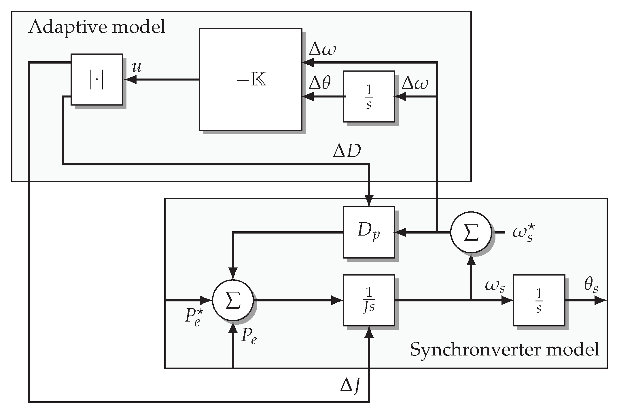
An AVI model based on linear dynamic systems is proposed. The proposed linear dynamic system’s state variables are the frequency deviation and the rotor angle deviation, and the control inputs are the virtual inertia and frequency droop gain.
The proposed AVI model is computed with an LQR control in order to minimize frequency deviations with minimum effort and, therefore, to manage an optimal balance between fast frequency response and WTGS stress during disturbances.
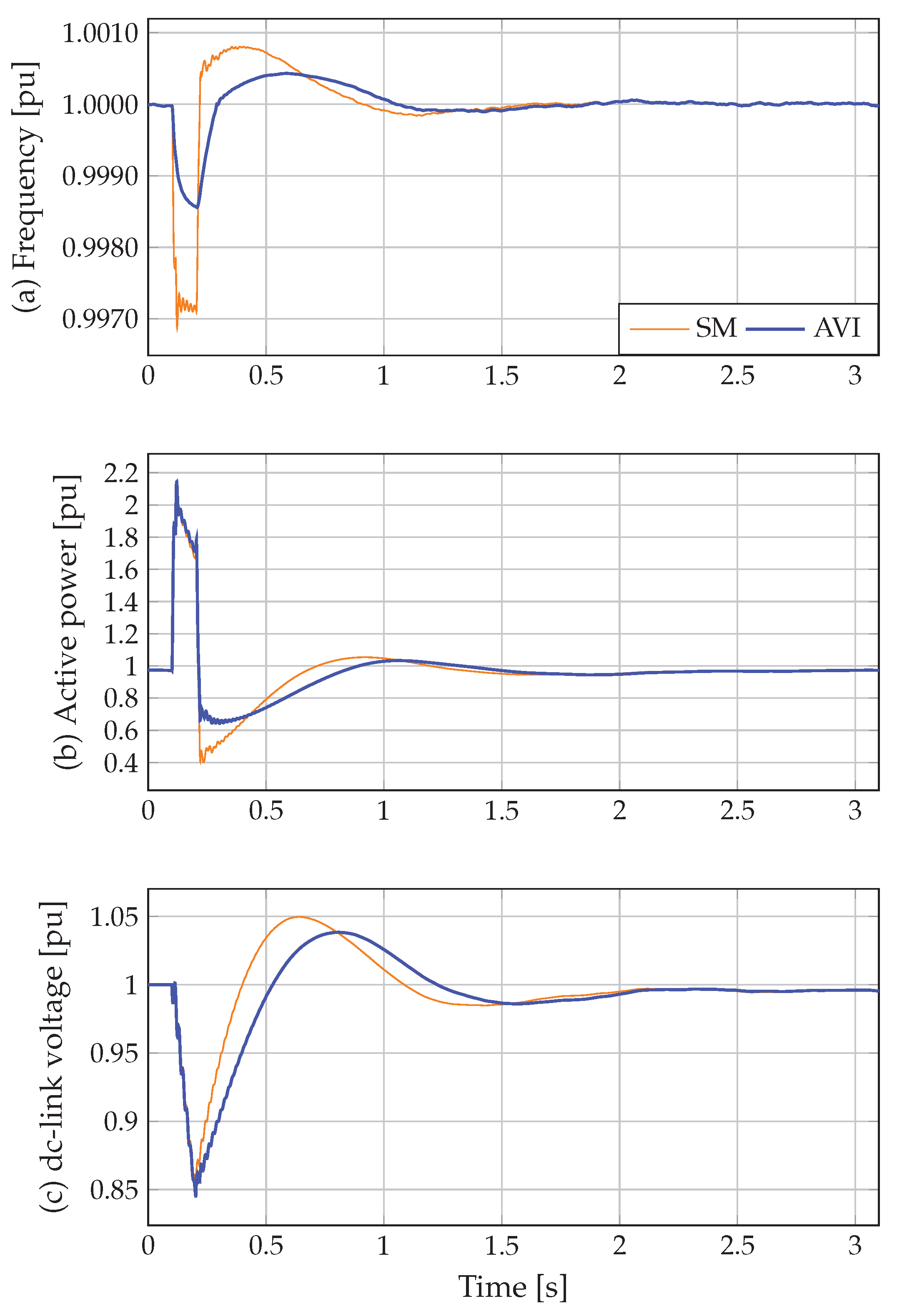
The performance of the proposed AVI model is evaluated in three different cases of wind speed considering a short-circuit. Furthermore, the proposed AVI model is compared with the conventional synchronverter model (SM), where, in all cases, the proposed AVI model has a better performance.
This study is organized as follows: Section 2 presents the main characteristics of the WTGS integrated with a permanent magnet machine and each one of its components; Section 3 describes the virtual synchronous machine modeling that allows working with a power electronic converter such as a dynamic frequency compensator; Section 4 presents the proposed linear quadratic regulator to provide adaptive virtual inertia to power systems using WTGS; Section 5 presents all the computational validation of the proposed control methodology using three different simulation cases: (i) short-circuit event with constant wind speed, (ii) short-circuit event with wind speed decreasing after fault, and (iii) the wind speed decreasing when short-circuit fault is presented. Finally, Section 6 presents the concluding remarks derived from this work.

2. Wind Energy Conversion System

The wind energy conversion system (WTGS) integrated into the grid through a back-to-back converter is depicted in Figure 1. The WTGS is composed of a wind turbine drive train, a permanent magnet synchronous machine (PMSG), a back-to-back converter, an RL-filter, and a transformer. The most important component of the WTGS is described in this section.

2.1. Wind Turbine Model

The wind turbine transforms the kinetic energy of the wind into mechanical kinetic energy in rotational form. Therefore, it is possible to obtain a relationship between mechanical power and aerodynamic wind turbine as follows,
p t = 1 2 ρ A C p ( λ , β ) V 3 ,
where ρ is the air density, A is the area covered by the turbine blades ( A = R π 2 , where R denotes the radius of the area covered by the blades), C p ( λ , β ) is the power coefficient, and V is the wind speed.
The power coefficient C p ( λ , β ) is a function of the pitch angle β and speed ratio λ [3] as follows,
C p ( λ , β ) = 0.5176 116 γ 0.4 β 5 e 21 γ + 0.0068 λ ,
with
1 γ = 1 λ + 0.008 β 0.035 β 3 + 1 ,
λ = ω T R V ,
where ω T is the angular speed in the wind turbine.
The pitch angle β is maintained at zero and is only controlled if V overpasses the rated wind speed so that the PMSG continues delivering its rated active power [16].
On the other hand, combining (1)–(4), it is possible to obtain the turbine output power as follows
τ t = p t ω T .
Figure 2 depicts the relationship between the angular speed ω T and turbine output power τ t . This figure shows that the maximum power output can be achieved at a particular angular speed while the pitch angle is zero. Therefore, the speed ratio λ must be in its optimum values λ o p t to maximize the power extracted from the wind energy system [3].

2.2. Permanent Magnet Synchronous Generator Model

The PMSG is installed between the wind turbine and the electrical network through a back-to-back converter, as shown in Figure 1. The mechanical and electrical equations in the d q reference frame that detail the dynamic behavior in values per unit of the PMSG can be written as
L w i ˙ d w = R w + L w ω r i w v d w , L w i ˙ q w = R w L w ω r i d w + ψ w ω e w v q w , 2 H t ω o ω ˙ r = τ t τ e w ,
where v d q w and i d q w represent the stator voltages and currents of the PMSG in d q reference frame, respectively. L w and R w denote the stator winding’s inductance and resistance of the electrical machine. In values per unit, ω r is equal to ω e w , ω o is the based rotational speed, and ψ w is constant permanent magnetic flux on the PMSG, which is as a function of the construction and material employed in the rotor of the PMSG [34]. H t is wind-turbine inertia time constant and τ e w is the electrical torque, which is defined as
τ e w = ψ w i q w .

3. Virtual Synchronous Machine Model

This section describes the synchronverter model, which was initially proposed in [27] in order to emulate the synchronous machine features using a voltage source converter. The schematic configuration of the synchronverter model implemented in the WTGS was illustrated in Figure 1. For simplicity, the operation modes of self-synchronized synchronverter were shown in Figure 1. The operation modes can be consulted in [31].
The virtual shaft of the synchronverter model can be represented as follows
J d d t ω s = τ m τ e D p ( ω s ω s ) ,
d d t θ s = ω s ,
where ω s and ω s are the synchronous frequency and its set-point, respectively. τ m and τ e are the mechanical and electrical torques, respectively. J and D p are the virtual inertia and the frequency droop gain, respectively, and θ s is the rotor angle. The mechanical and electrical torques are determined as
τ m = P ω s ,
τ e = P ω s ,
where P is power torque applied to the shaft and P is real power delivered by synchronverter machine, which can be calculated as
P = ψ ω s i a b c , sin ^ θ s ,
with
sin ^ θ s = sin θ s , sin θ s + 2 3 π , sin θ s + 2 3 π ,
where . , . represents the conventional inner product in R 3 . i a b c = [ i a , i b , i c ] is the output phase currents vector of the synchronverter, while ψ is its virtual flux, and it is calculated as follows,
K ψ d d t ψ = Q Q + D q v v s ,
with
K ψ = D q τ v ω s ,
where Q and Q are the output active power of the synchronverter and its set-point, respectively. v s and v s are the output voltage magnitude of the synchronverter and its set-point, respectively. K ψ denotes the reactive power controller integral, D q is the voltage droop gain, and τ v is its time constant. The output reactive power of the synchronverter can be defined as
Q = ψ ω s i a b c , cos ^ θ s .
In steady-state, ω s ω s , and hence, the mechanical and electrical torques can be approximated as follows
τ m P ω s ,
τ e P ω s ,
In this case, the power torque is computed to control the dc-link voltage, which is determined by a PI controller as presented in Figure 1 and can be given by
P = k p v d c + k i v d c s v d c v d c
where k p v d c and k i v d c are the proportional and integral gains of the dc voltage controller, respectively. v d c and v d c are the dc voltage and its set-point.
Next, we need to define the phase terminal voltage ( v a b c = [ v a , v b , v c ] ) of the synchronverter to obtain its complete model. The phase terminal voltage can be written as
v a b c = R s i a b c + L s d d t i a b c + e a b c
where R s and L s are the stator winding resistance and inductance matrices, respectively. e a b c = [ e a , e b , e c ] is the back electromotive force (EMF) of the synchronverter, which is the control input of pulse-width-modulation. The EMF can be written as
e a b c = ψ ω s sin ^ θ s .

4. Adaptive Virtual Inertia

The adaptive virtual inertia developed in this study is focused on proposing a linear dynamic system that uses the frequency deviation ( Δ ω ) and the rotor angle deviation ( Δ θ ) as the state variables and the virtual inertia and frequency droop gain as the control variables. We consider that the virtual inertia and frequency droop gain can be formulated as
J D p = J 0 D p 0 + Δ J Δ D p
where subscript 0 denotes initial values and Δ J and Δ D p represent the adaptive inertia and adaptive frequency droop gain, respectively, which can be represented as
Δ J Δ D p = K Δ ω s Δ θ = K 11 K 12 K 21 K 22 Δ ω s Δ θ
where K is the feedback matrix gain.
The problem in (22) is to find a relationship between the adaptive values and the state variables to obtain a suitable K matrix. For this purpose, we linearize (8) and (9) as follows,
Δ ω s ˙ = τ m 0 J 0 2 Δ J τ e 0 J 0 Δ ω s Q 0 J 0 Δ θ + P 0 Δ J D p 0 J 0 Δ ω s ω s J 0 Δ D p + D p 0 ω s J 0 2 Δ J , Δ θ s ˙ = Δ ω s ,
where P 0 , τ m 0 , and τ e 0 are the initial conditions.
The linear system (23) can be rewritten as the state-space model
Δ x ˙ = A Δ x + B Δ u , y = C Δ x + D Δ u ,
with
A = τ e 0 + D p 0 J 0 Q 0 J 0 1 0 , B = τ m 0 + P 0 D p 0 ω s J 0 2 ω s J 0 0 0 , C = 1 0 0 1 , D = 0 0 0 0 ,
Δ u = Δ J Δ D p , Δ x = Δ ω s Δ θ .
Observe that we have a relationship between the adaptive values and the state variables described by (24). Next, in order to ensure the optimal balance between fast frequency response and WTGS stress during disturbances, an optimization problem is proposed to minimize frequency deviations with minimum effort as follows
min 0 1 2 Δ x T F Δ x + Δ u T D Δ u d t s . t Δ x ˙ = A Δ x + B Δ u Δ u = K Δ x
where F = d i a g ( F 1 , F 2 ) 0 represents the error penalty matrix and D = d i a g ( D 1 , D 2 ) 0 denotes the control signal penalty matrix. The optimization problem (25) permits finding the optimal feedback matrix gain K = D 1 B G , where G is the solution to the following algebraic Riccati Equation (for more details about the LQR to see [35]):
0 = A T G + G A G B D 1 B G + F .
Note in (22) that the frequency deviation can take the positive and negative values. This means that sometimes adaptive inertia and adaptive frequency droop gain can take negative values; hence, the total system inertia will decrease, deteriorating the performance of the system. In order to avoid this, adaptive inertia and adaptive frequency droop gain are computed:
J = J 0 + Δ J ,
D p = D p 0 + Δ D p .
Figure 3 illustrates the implementation of the proposed adaptive model on the synchronverter model.

5. Test System and Simulation Results

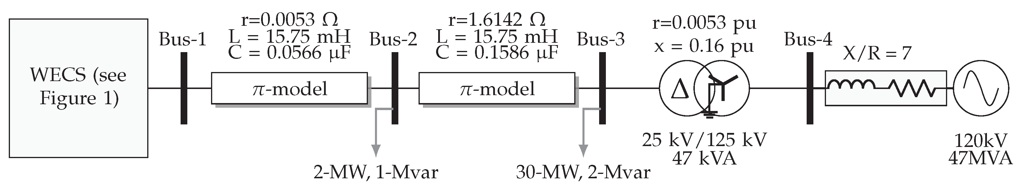
5.1. The Test System

A grid-connected WTGS was implemented in Matlab/Simulink 2020b platform with Simscape Electrical in order to demonstrate the effectiveness of the proposed adaptive virtual model. The simulations were run with fixed-step, and the solver used was discrete (no continuous state). The simple time was configured as 5 × 10 6 s. The test system is illustrated in Figure 4, which consists of a 100-kW type-IV WTGS using a configuration back-to-back converter connected to a 25-kV step down to a 260 V grid. The WTGS-side converter had an optimal torque MPPT algorithm, and the grid-side converter was implemented with the synchronverter algorithm described in Section 3. The parameters of WTGS and the synchronverter are presented in Table 2 and Table 3, respectively.

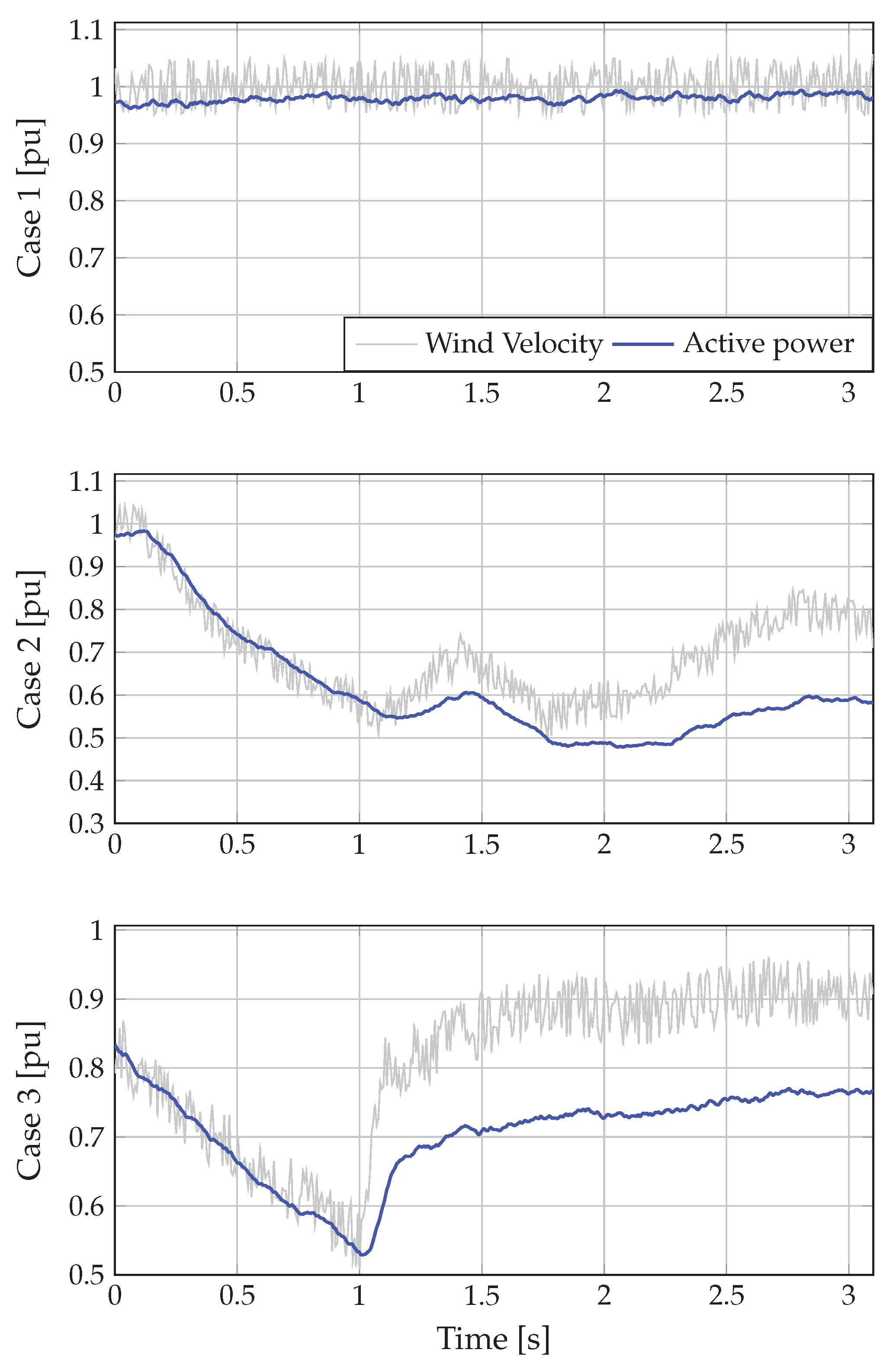
5.2. Simulation Cases

Three cases are proposed to demonstrate the effectiveness of the proposed adaptive virtual model. In addition, the proposed model is compared with the conventional synchronverter model (SM). The proposed cases are:
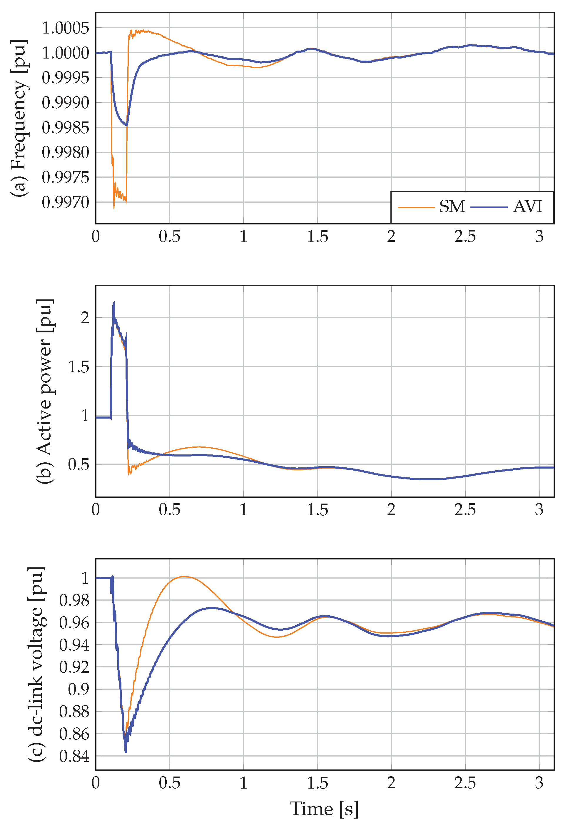
  • Case 1: The wind speed is constant while a short-circuit at grid-side converter (bus-1) with a period of 100 ms is assumed.
  • Case 2: A drop in wind speed is considered after a three-phase to ground (bus-1) with a period of 100 ms.
  • Case 3: A drop in wind speed is considered during a three-phase to ground (bus-1) with a period of 100 ms.
Figure 5 illustrates the wind speed and the active power delivered in dc-link by WTGS in each case considered.
On the other hand, the integral of time-weighted absolute error ( I ) is also employed to assess the performance of the proposed adaptive virtual inertial (AVI) based on the LQR optimization. The I is computed for the frequency of the synchronverter and dc-link voltage as follows
I ω = 0 t f t ω s ω s d t , I v = 0 t f t v d c v d c d t ,
where t f is the total simulation time. The maximum and minimum values are also calculated to quantify the performance of the proposed model. Furthermore, the rate change of the frequency (RoCoF) is employed for the frequency.

5.3. Simulation Results

5.3.1. Case 1

In this case, the ability of the proposed adaptive virtual inertia was studied when a short-circuit at grid-side converter occurs. Figure 6 shows the dynamic responses of the synchronverter frequency, the active power at bus 1, and dc-link voltage. The performance indexes for case 1 are shown in Table 4.
Observe in Figure 6a that the synchronverter frequency stabilizes in a shorter time when the AVI is implemented. This is supported by contrasting I ω for both approaches in Table 4. This index is reduced by 60.42%. Additionally, the maximum and minimum frequency values are lower for the proposed adaptive model than the SM approach, which are reduced by 46.61% and 53.74%, respectively, (see Table 4). The RoCoF also is reduced by 79.41% when the AVI is implemented.
Figure 6b shows that the active power delivered by synchronverter at bus 1 presents a better behavior for the proposed adaptive model than the SM approach, since the active power stabilizes in a shorter time. However, this better behavior only occurs after the fault ends since both approaches have the same performance during the fault.
Figure 6c shows that the dc-link voltage shows an enhanced response when the adaptive virtual inertia is considered by recovering the dc-link voltage in a shorter time with a lower overpass. This implies that the proposed model helps to improve the dc-link voltage regulation. This improvement is easy to notice in Figure 6, where the proposed model’s response is clearer when the approaches are compared. This analysis is supported by comparing I v between the approaches (see Table 4), where this index is reduced by 15.34% for the proposed AVI.

5.3.2. Case 2

This case investigates the ability of the proposed model to enhance the synchronverter response when there is a high drop in the wind speed immediately after a short circuit occurred. The synchronverter frequency, the active power at bus 1, and dc-link voltage for case 2 are depicted in Figure 7, while Table 4 lists the performance indexes.
Figure 7a shows that the proposed AVI continues showing better performance for the frequency compared with the synchronverter model. Hence, the WTGS system’s response behavior has been improved. This can be verified by comparing the I ω and RoCoF in Table 4 for case 2, where these indexes are reduced by 34.66% and 84.61%, respectively. Additionally, the maximum and minimum values of the frequency are also reduced by 67.03% and 52.67%, respectively, when the proposed AVI is implemented.
The dynamic response of the active power delivered (see Figure 7b) by synchronverter at bus 1 has a similar behavior as presented in case 1. In this case, the active power continues stabilizing in a shorter time when the proposed adaptive model is considered. As in case 1, this better response only happens after the fault.
In Figure 6c, it can be noted that the dc-link voltage continues to recover faster for the AVI approach than for the SM approach. Here, I v continues to be reduced for the proposed AVI (see Table 4), which is reduced by 22.36%.

5.3.3. Case 3

This case analyzes the AVI approach’s ability to improve the WTGS response integrated to the grid with the synchronverter model when a high drop in wind speed is considered during a three-phase to ground. Figure 8 illustrates the dynamic responses of the synchronverter frequency, the active power at bus 1, and dc-link voltage. Table 4 shows the performance index.
Note in Figure 8 that dynamic responses of the synchronverter model with the AVI approach continue presenting an enhanced response for frequency as well as dc-link voltage, even when the wind speed continues to drop compared to the conventional synchronverter model. This demonstrates that the proposed AVI improves the transient response of the system. This is supported by analyzing the performance indexes in Table 4, where I ω and RoCoF are lower for the proposed AVI than the SM approach, with a reduction by 51.32% and 84.61%, respectively. For the dc-link voltage (see Figure 8), observe that the proposed adaptive model continues recovering the dc-link voltage faster than the SM approach, where I v is reduced by 17.16%.

6. Conclusions and Future Works

An adaptive virtual inertia model for the synchronverter model implemented in a WTGS was proposed to improve the dynamic response under large disturbance. The WTGS was integrated into the grid through a back-to-back converter, and its grid-side converter implemented the synchronverter model with and without the proposed AVI. The proposed AVI was developed under a linear dynamic system that used the frequency deviation and the rotor angle deviation as the state variables, while the virtual inertia and frequency droop gain were used as the control variables. This linear dynamic system was solved with an LQR in order to reduce the proposed AVI frequency deviations with minimum effort. Several case simulations were implemented and compared with the conventional synchronverter model to prove the effectiveness and feasibility of the proposed LQR-based adaptive virtual inertia synchronverter. The maximum and minimum frequency, RoCoF, and I w were used to validate the advantages of the proposed AVI. The frequency response showed better performance and lower frequency oscillations than the synchronverter model with constant inertia. In the worst cases, the maximum and minimum frequency were by 46.61% and 52.67% when the proposed AVI was implemented. At the same time, RoCoF and I w were also reduced by 79.41% and 34.66%.
As future works it will be possible to develop the following research: (i) applying the proposed model in the photovoltaic system; (ii) integrating the proposed model in isolated renewable hybrid power systems; (iii) computing the adaptive inertia and droop gain with other methods as a model-predictive control.

Author Contributions

Conceptualization, W.G.-G., O.D.M., A.E.-M., and J.C.H.; Methodology, W.G.-G. and O.D.M.; Investigation, W.G.-G. and O.D.M.; Writing—review and editing, W.G.-G., O.D.M., A.E.-M., and J.C.H. All authors have read and agreed to the published version of the manuscript.

Funding

This research received no external funding.

Conflicts of Interest

The authors declare no conflict of interest.

Abbreviations

The following abbreviations are used in this manuscript:
λ o p t Optimum value of the speed ratio
ω r Angular speed in the PMSG shaft
ω s Angular frequency reference of the synchronverter machine
ψ w Permanent magnetic flux on the PMSG
ρ Air density
τ v Time constant for the voltage droop controller
AArea covered by the turbine blades
C g Inverter filter capacitance of the system
D p Frequency droop gain of the synchronverter machine
D q Voltage droop gain of the synchronverter machine
D p 0 Initial frequency droop gain
D q 0 Initial voltage droop gain
f Rated grid frequency of the system
H t Wind-turbine inertia time constant
JVirtual inertia of the synchronverter machine
J 0 Initial moment of inertia
K ψ Reactive power controller integral
k i v d c Integral gain of the dc voltage controller
k p v d c Proportional gain of the dc voltage controller
L g Inverter filter inductance of the system
L s Stator winding’s inductance of the synchronverter machine
L w Stator winding’s inductance of the PMSG
P Power torque applied to the synchronverter machine shaft
Q Reactive power reference by synchronverter machine
RRadius of the area covered by the blades
R g Inverter filter resistance of the system
R s              Stator winding’s resistance of the synchronverter machine
R w Stator winding’s resistance of the PMSG
SRated power of the system
v Output voltage magnitude reference of the synchronverter machine
v d c dc-link voltage reference
v l i n e Rated grid voltage line-to-line of the system
Variables
β Pitch angle
Δ D p Adaptive frequency droop
Δ J Adaptive virtual inertia
Δ ω Frequency deviation
Δ θ Rotor angle deviation
λ Speed ratio
K Feedback matrix gain
ω s Angular frequency of the synchronverter machine
ω T Angular speed in the wind turbine
ω e w Electrical angular speed of the PMSG
ψ Virtual flux of the synchronverter machine
τ e Electrical torque of the synchronverter machine
τ m Mechanical torque of the synchronverter machine
τ t Turbine output power
τ e w Electrical torque of the PMSG
θ s Rotor angle of the synchronverter machine
C p ( λ , β ) Power coefficient
e a b c Electromotive force of the synchronverter machine
i a b c Output phase currents vector of the synchronverter machine
e q d w Stator currents of the PMSG in dq reference frame
PReal power delivered by synchronverter machine
p t Turbine power
Q          Reactive power delivered by synchronverter machine
V          Wind speed
v          Output voltage magnitude of the synchronverter machine
v d c          dc-link voltage
v d q w          Stator voltages of the PMSG in d q reference frame

References

  1. Baran, J.; Jąderko, A. An MPPT Control of a PMSG-Based WECS with Disturbance Compensation and Wind Speed Estimation. Energies 2020, 13, 6344. [Google Scholar] [CrossRef]
  2. Yaramasu, V.; Wu, B.; Sen, P.C.; Kouro, S.; Narimani, M. High-power wind energy conversion systems: State-of-the-art and emerging technologies. Proc. IEEE 2015, 103, 740–788. [Google Scholar] [CrossRef]
  3. Heier, S. Grid Integration of Wind Energy: Onshore and Offshore Conversion Systems; John Wiley & Sons: Hoboken, NJ, USA, 2014. [Google Scholar]
  4. Marin-Hurtado, A.; Escobar-Mejía, A.; Gil-González, W. Adaptive Inertia for a Virtual Synchronous Machine Using an LQR Controller Applicable to a High-Voltage DC Terminal. In Proceedings of the 2020 IEEE ANDESCON, Quito, Ecuador, 13–16 October 2020; IEEE: Piscataway, NJ, USA, 2020; pp. 1–6. [Google Scholar]
  5. Kashem, S.B.A.; Chowdhury, M.E.; Ahmed, J.; Ashraf, A.; Shabrin, N. Wind Power Integration with Smart Grid and Storage System: Prospects and Limitations. Int. J. Adv. Comput. Sci. Appl. 2020, 11, 552–569. [Google Scholar] [CrossRef]
  6. Amin, M.; Molinas, M. Self-synchronisation of wind farm in MMC-based HVDC system. In Proceedings of the 2016 IEEE Electrical Power and Energy Conference (EPEC), Ottawa, ON, Canada, 12–14 October 2016; IEEE: Piscataway, NJ, USA, 2016. [Google Scholar] [CrossRef] [Green Version]
  7. Do, T.D. Disturbance Observer-Based Fuzzy SMC of WECSs Without Wind Speed Measurement. IEEE Access 2017, 5, 147–155. [Google Scholar] [CrossRef]
  8. Watil, A.; Magri, A.E.; Raihani, A.; Lajouad, R.; Giri, F. Multi-objective output feedback control strategy for a variable speed wind energy conversion system. Int. J. Electr. Power Energy Syst. 2020, 121, 106081. [Google Scholar] [CrossRef]
  9. Beltran, B.; Benbouzid, M.E.H.; Ahmed-Ali, T. Second-Order Sliding Mode Control of a Doubly Fed Induction Generator Driven Wind Turbine. IEEE Trans. Energy Convers. 2012, 27, 261–269. [Google Scholar] [CrossRef] [Green Version]
  10. Majdoub, Y.; Abbou, A.; Akherraz, M. Variable speed control of DFIG-wind turbine with wind estimation. In Proceedings of the 2014 International Renewable and Sustainable Energy Conference (IRSEC), Ouarzazate, Morocco, 17–19 October 2014; IEEE: Piscataway, NJ, USA, 2014. [Google Scholar] [CrossRef]
  11. Li, D.Y.; Cai, W.C.; Li, P.; Jia, Z.J.; Chen, H.J.; Song, Y.D. Neuroadaptive Variable Speed Control of Wind Turbine with Wind Speed Estimation. IEEE Trans. Ind. Electron. 2016, 63, 7754–7764. [Google Scholar] [CrossRef]
  12. Song, D.; Yang, J.; Dong, M.; Joo, Y.H. Model predictive control with finite control set for variable-speed wind turbines. Energy 2017, 126, 564–572. [Google Scholar] [CrossRef]
  13. Boukhezzar, B.; Siguerdidjane, H. Nonlinear control with wind estimation of a DFIG variable speed wind turbine for power capture optimization. Energy Convers. Manag. 2009, 50, 885–892. [Google Scholar] [CrossRef]
  14. Boukhezzar, B.; Siguerdidjane, H. Comparison between linear and nonlinear control strategies for variable speed wind turbines. Control Eng. Pract. 2010, 18, 1357–1368. [Google Scholar] [CrossRef]
  15. Calabrese, D.; Tricarico, G.; Brescia, E.; Cascella, G.L.; Monopoli, V.G.; Cupertino, F. Variable Structure Control of a Small Ducted Wind Turbine in the Whole Wind Speed Range Using a Luenberger Observer. Energies 2020, 13, 4647. [Google Scholar] [CrossRef]
  16. Kim, Y.S.; Chung, I.Y.; Moon, S.I. Tuning of the PI Controller Parameters of a PMSG Wind Turbine to Improve Control Performance under Various Wind Speeds. Energies 2015, 8, 1406–1425. [Google Scholar] [CrossRef] [Green Version]
  17. Li, P.; Wang, J.; Xiong, L.; Wu, F. Nonlinear Controllers Based on Exact Feedback Linearization for Series-Compensated DFIG-Based Wind Parks to Mitigate Sub-Synchronous Control Interaction. Energies 2017, 10, 1182. [Google Scholar] [CrossRef] [Green Version]
  18. Kim, K.; Kim, H.G.; Song, Y.; Paek, I. Design and Simulation of an LQR-PI Control Algorithm for Medium Wind Turbine. Energies 2019, 12, 2248. [Google Scholar] [CrossRef] [Green Version]
  19. Yang, J.; Wu, J.; Dong, P.; Yang, J. Passivity-based control in wind turbine for maximal energy capture. In Proceedings of the 2004 IEEE International Conference on Electric Utility Deregulation, Restructuring and Power Technologies Proceedings, Hong Kong, China, 5–8 April 2004; IEEE: Piscataway, NJ, USA, 2004. [Google Scholar] [CrossRef]
  20. Cisneros, R.; Gao, R.; Ortega, R.; Husain, I. A PI-passivity-based control of a wind energy conversion system enabled with a solid-state transformer. Int. J. Control 2020, 1–11. [Google Scholar] [CrossRef]
  21. Gao, R.; Husain, I.; Cisneros, R.; Ortega, R. Passivity-based and standard PI controls application to wind energy conversion system. In Proceedings of the 2016 IEEE Energy Conversion Congress and Exposition (ECCE), Milwaukee, WI, USA, 18–22 September 2016; IEEE: Piscataway, NJ, USA, 2016. [Google Scholar] [CrossRef]
  22. Mancilla-David, F.; Ortega, R. Adaptive passivity-based control for maximum power extraction of stand-alone windmill systems. Control Eng. Pract. 2012, 20, 173–181. [Google Scholar] [CrossRef]
  23. Azeem, B.; Rehman, F.; Mehmood, C.; Ali, S.; Khan, B.; Saeed, S. Exact Feedback Linearization (EFL) and De-Couple Control of Doubly Fed Induction Generator Based Wind Turbine. In Proceedings of the 2016 International Conference on Frontiers of Information Technology (FIT), Islamabad, Pakistan, 19–21 December 2016; IEEE: Piscataway, NJ, USA, 2016. [Google Scholar] [CrossRef]
  24. Jose, J.T.; Chattopadhyay, A.B. Mathematical Formulation of Feedback Linearizing Control of Doubly Fed Induction Generator Including Magnetic Saturation Effects. Math. Probl. Eng. 2020, 2020, 1–10. [Google Scholar] [CrossRef]
  25. Suul, J.A.; D’Arco, S.; Rodriguez, P.; Molinas, M. Extended stability range of weak grids with Voltage Source Converters through impedance-conditioned grid synchronization. In Proceedings of the 11th IET International Conference on AC and DC Power Transmission, Birmingham, UK, 10–12 February 2015. [Google Scholar]
  26. Amin, M.; Rygg, A.; Molinas, M. Self-synchronization of wind farm in an MMC-based HVDC system: A stability investigation. IEEE Trans. Energy Convers. 2017, 32, 458–470. [Google Scholar] [CrossRef]
  27. Zhong, Q.C.; Weiss, G. Synchronverters: Inverters That Mimic Synchronous Generators. IEEE Trans. Ind. Electron. 2011, 58, 1259–1267. [Google Scholar] [CrossRef]
  28. Zhong, Q.C.; Ma, Z.; Ming, W.L.; Konstantopoulos, G.C. Grid-friendly wind power systems based on the synchronverter technology. Energy Convers. Manag. 2015, 89, 719–726. [Google Scholar] [CrossRef]
  29. Yap, K.Y.; Sarimuthu, C.R.; Lim, J.M.Y. Grid Integration of Solar Photovoltaic System Using Machine Learning-Based Virtual Inertia Synthetization in Synchronverter. IEEE Access 2020, 8, 49961–49976. [Google Scholar] [CrossRef]
  30. Aouini, R.; Marinescu, B.; Kilani, K.B.; Elleuch, M. Synchronverter-based emulation and control of HVDC transmission. IEEE Trans. Power Syst. 2015, 31, 278–286. [Google Scholar] [CrossRef]
  31. Zhong, Q.C.; Nguyen, P.L.; Ma, Z.; Sheng, W. Self-synchronized synchronverters: Inverters without a dedicated synchronization unit. IEEE Trans. Power Electron. 2013, 29, 617–630. [Google Scholar] [CrossRef]
  32. Wang, C.; Meng, J.; Wang, Y.; Wang, H. Adaptive virtual inertia control for DC microgrid with variable droop coefficient. In Proceedings of the 2017 20th International Conference on Electrical Machines and Systems (ICEMS), Sydney, NSW, Australia, 11–14 August 2017; IEEE: Piscataway, NJ, USA, 2017. [Google Scholar] [CrossRef]
  33. Blau, M.; Weiss, G. Synchronverters used for damping inter-area oscillations in two-area power systems. Renew. Energy Power Qual. J. 2018, 45–50. [Google Scholar] [CrossRef]
  34. Gil-González, W.; Garcés, A.; Fosso, O.B. Passivity-based control for small hydro-power generation with PMSG and VSC. IEEE Access 2020, 8, 153001–153010. [Google Scholar] [CrossRef]
  35. Anderson, B.D.; Moore, J.B. Optimal Control: Linear Quadratic Methods; Courier Corporation: North Chelmsford, MA, USA, 2007. [Google Scholar]
Figure 1. Schematic configuration of the synchronverter model and WTGS.
Electronics 10 01022 g001
Figure 2. Turbine power characteristics with β = 0 .
Electronics 10 01022 g002
Figure 3. Proposed adaptive virtual inertia model.
Electronics 10 01022 g003
Figure 4. Grid-connected WTGS implemented with a synchronverter model
Electronics 10 01022 g004
Figure 5. Wind velocity and active power delivered by WTGS for all cases.
Electronics 10 01022 g005
Figure 6. Dynamic responses for case 1: (a) frequency, (b) active power, and (c) dc-link voltage.
Electronics 10 01022 g006
Figure 7. Dynamic responses for case 2: (a) frequency, (b) active power, and (c) dc-link voltage.
Electronics 10 01022 g007
Figure 8. Dynamic responses for case 2: (a) frequency, (b) active power, and (c) dc-link voltage.
Electronics 10 01022 g008
Table 1. Control techniques applied to WTGS.
Control MethodControl ObjectiveReference
Fuzzy sliding mode controlDisturbance rejection without wind speed measures[7]
Integral sliding mode controlMaximum power point tracking (MPPT)[8]
Second-order sliding mode controlMPPT[9]
Backstepping controlMPPT[10]
Neuroadaptive speed controllerMPPT with uncertain dynamics[11]
Model predictive controlMPPT[12]
Feedback-PI controllerSpeed control with disturbance rejection[13]
LQG (versus linear/nonlinear control)Speed control with disturbance rejection[14]
PI controlMPPT with tip-speed ratio[15]
PI controlPMSG WT[16]
PI controlPMSG with variable-speed fixed-pitch[17]
LQR-PI controlPMSG[18]
Passivity-based control (PBC)MPPT[19]
PI-PBCMPPT with estimator wind speed[20]
Robust PI-PBC controllerMPPT[21]
Adaptive standard PBCMPPT with estimator wind speed[22]
Exact feedback linearizationDIFG[23]
Feedback linearizationMPPT[24]
Exact feedback linearizationDIFG and voltage compensation[17]
Feedback linearizationMPPT[24]
Table 2. Parameters of the synchronverter.
ParameterValueParameterValue
DC-link voltage ( v d c )500 VRated power (S)100 kVA
Rated grid voltage ( v l i n e )260 VRated grid frequency ( f )60 Hz
Rated angular frequency ( ω s )376.99 rad/sInverter filter inductance ( L g )0.25 mH
Inverter filter resistance ( R g )1.885 m Ω Inverter filter capacitance ( C g )15.35 µF
Frequency droop gain ( D p 0 )10.4 W/(rad/s)Voltage droop gain ( D q 0 )5.2 Var/V
Reactive power set-point ( Q )0 VarMoment of inertia ( J 0 )0.104 kg m 2
Proportional regulator gain ( K p v d c )5 puIntegral regulator gain ( K i v d c )0.02 pu
Table 3. Parameters of the WTGS.
ParameterValueParameterValue
Rated power of the PMSG100 kVARated output power of the turbine100 W
Rated rotational speed ω r 2 π 90 Rated wind speed (V)12 m/s
Stator winding´s resistance ( R w )0.006 Ω Stator winding´s inductance ( L d w = L q w )0.3 mH
Magnetic flux ( ψ w )0.8 WbPole pairs ( N p )90
Inertia ( H t )20,000 kg m 2 Viscous damping0.01 Nms
Table 4. Performance indexes.
FrequencyDc-Link Voltage
I ω Max. [pu]Min. [pu]RoCof [pu/s] I v Max. [pu]Min. [pu]
Case 1SM0.92191.00080.99690.351370.87561.04960.8500
AVI0.36491.00040.99850.072360.70151.03830.8443
Case 2SM0.89911.00050.99680.350557.08161.00130.8488
AVI0.58741.00010.99850.060444.31281.00130.8431
Case 3SM1.10721.00230.99680.3614105.21541.06330.9362
AVI0.53891.00050.99840.055687.15361.02200.9344
Publisher’s Note: MDPI stays neutral with regard to jurisdictional claims in published maps and institutional affiliations.

