
Review of Power Converter Impact of Electromagnetic Energy Harvesting Circuits and Devices for Autonomous Sensor Applications


Abstract
:1. Introduction
2. Phenomenon of Electromagnetic
2.1. Mounting of Electromagnetic Vibration Generators
2.2. Mounting of Electromagnetic Damping
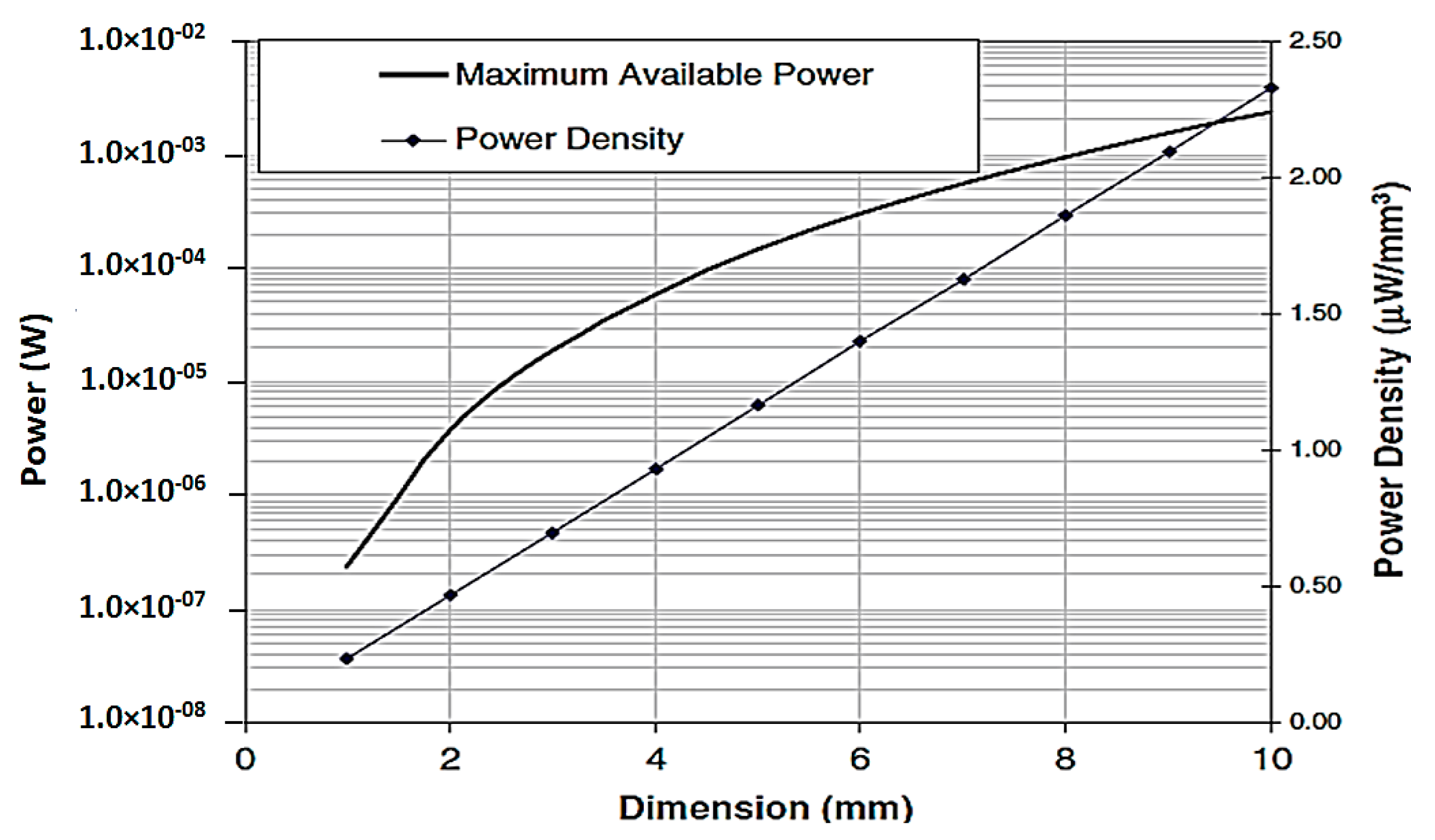
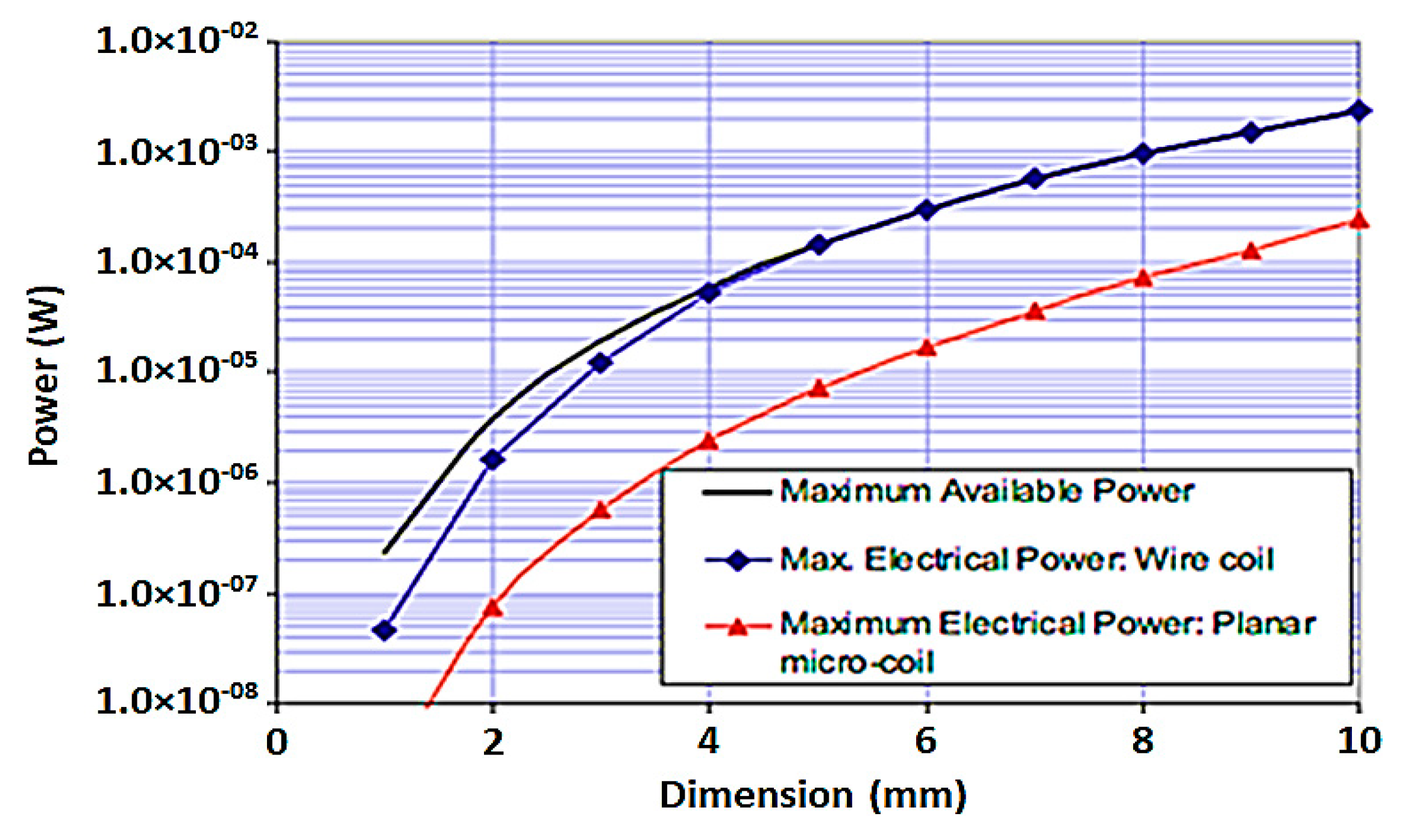
2.3. Maximum Power from an Electromagnetic Generator
3. Relation between Electromagnetic Energy Harvesting and Autonomous Sensors
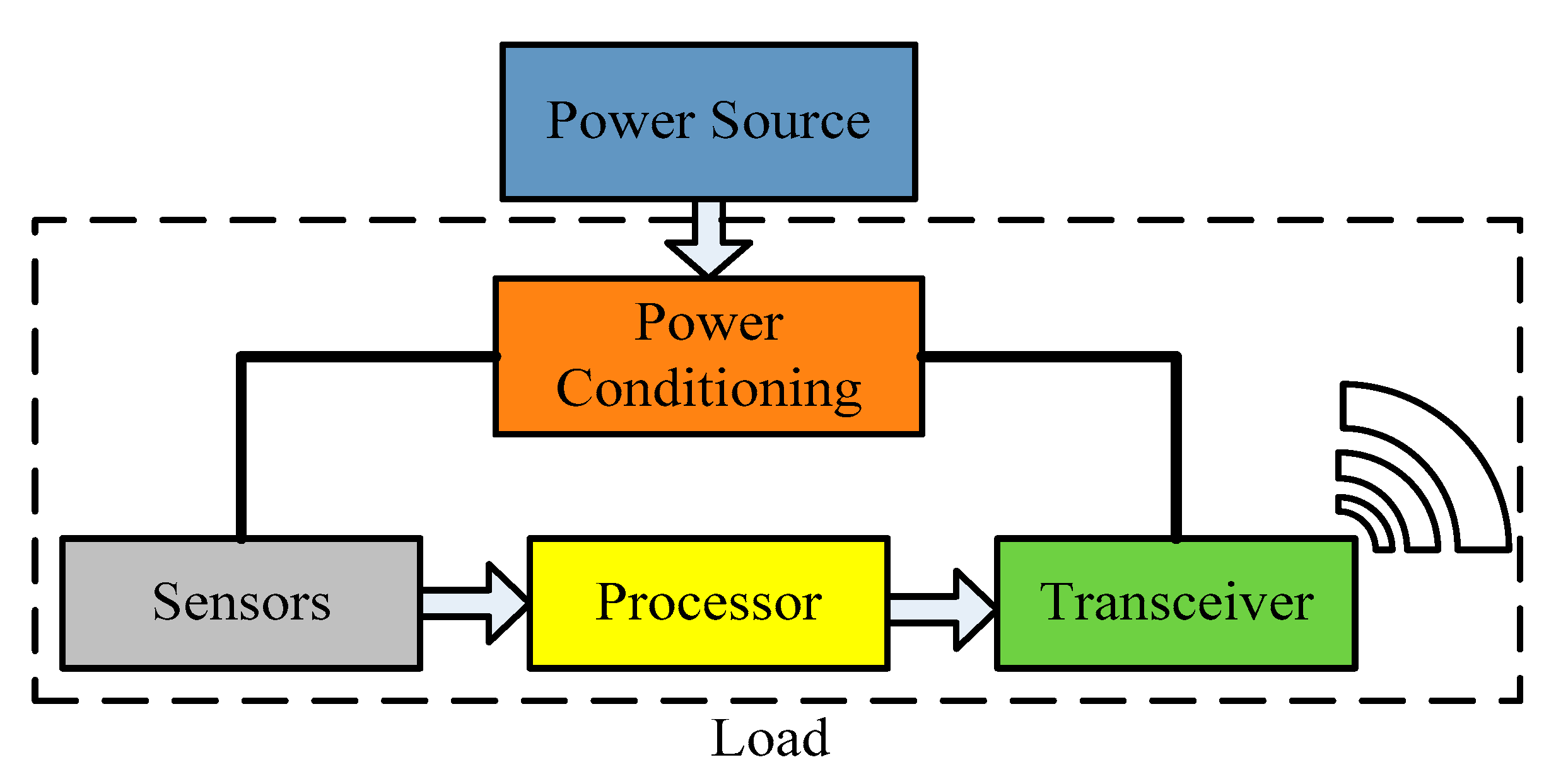
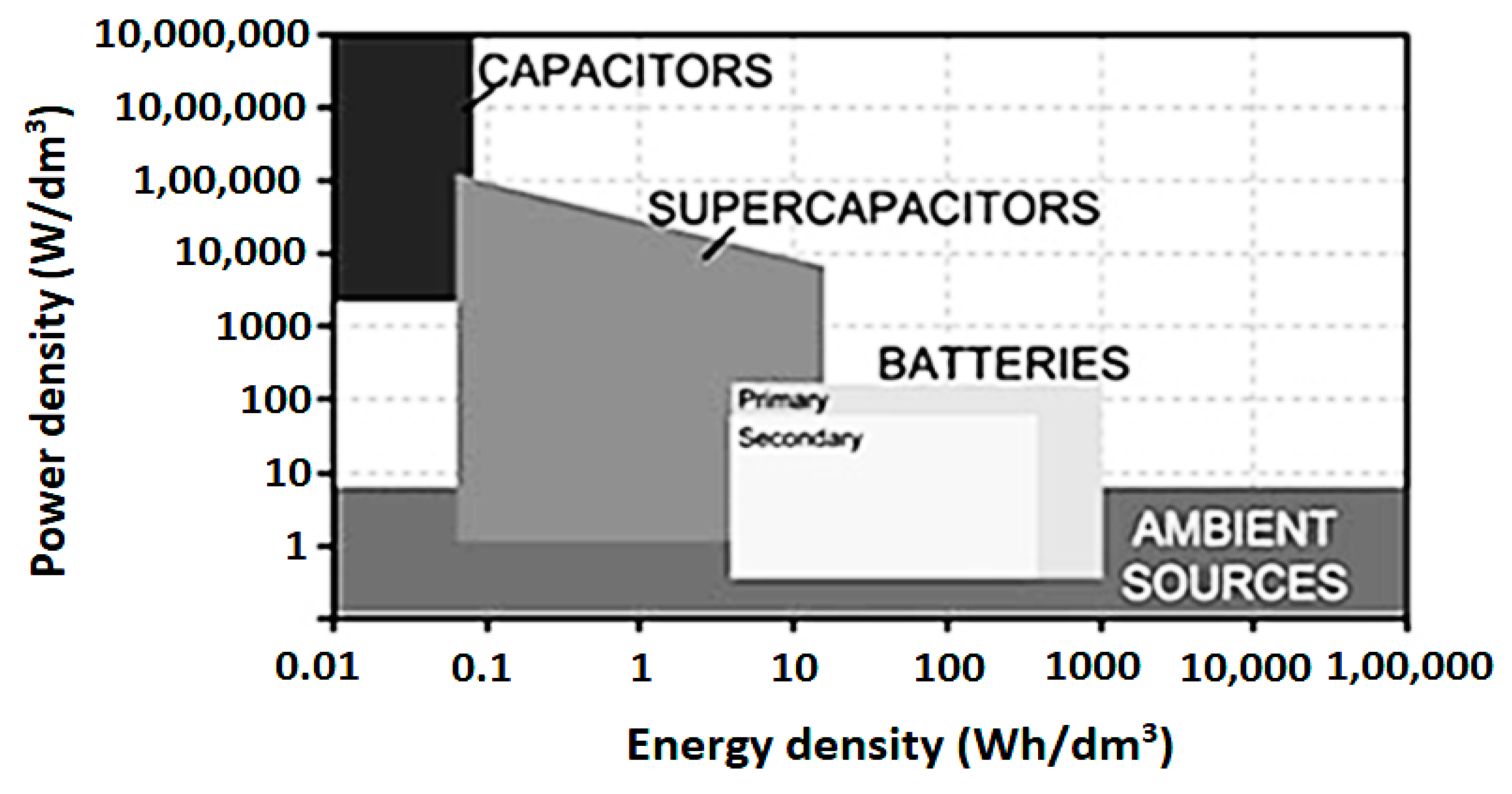
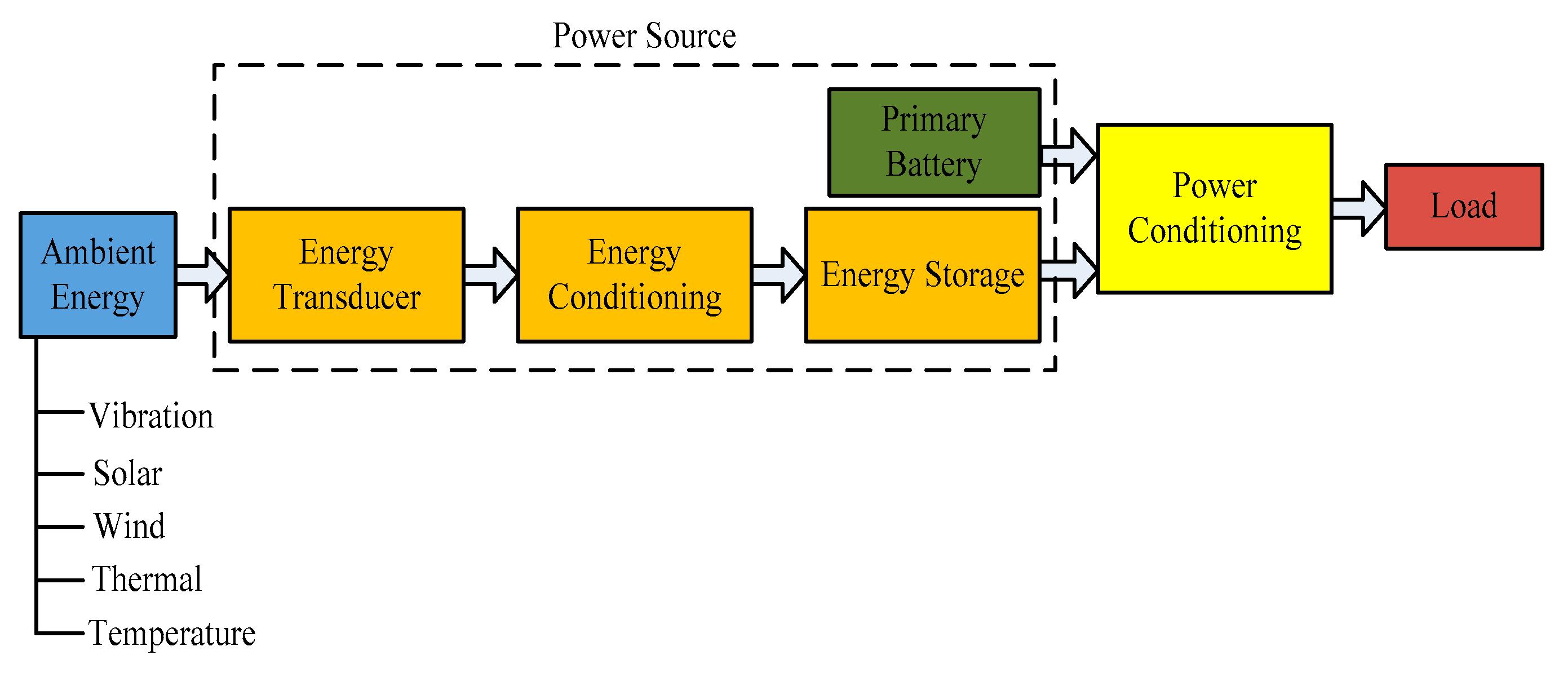
3.1. Autonomous Sensors Power Source
3.2. Autonomous Sensor in Electromagnetic Energy Harvesting Systems
3.3. Autonomous Sensor in Hybrid Electromagnetic Energy Harvesting Systems
3.4. Autonomous Sensors Electromagnetic Energy Harvesting Systems with Radio Frequency
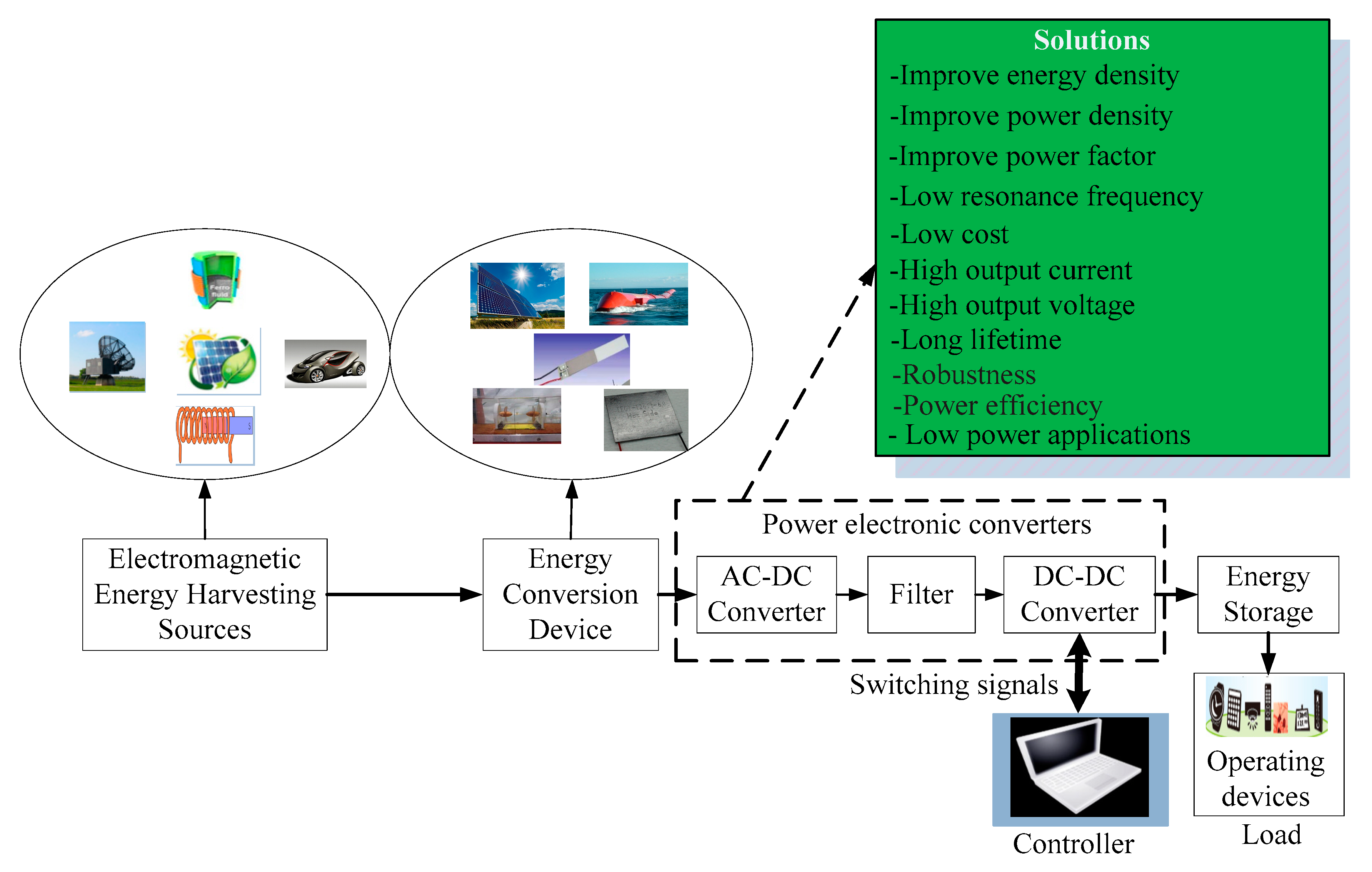
4. Power Electronic Technologies in Electromagnetic Energy Harvesting
4.1. A Standard Circuit for Energy-Harvesting
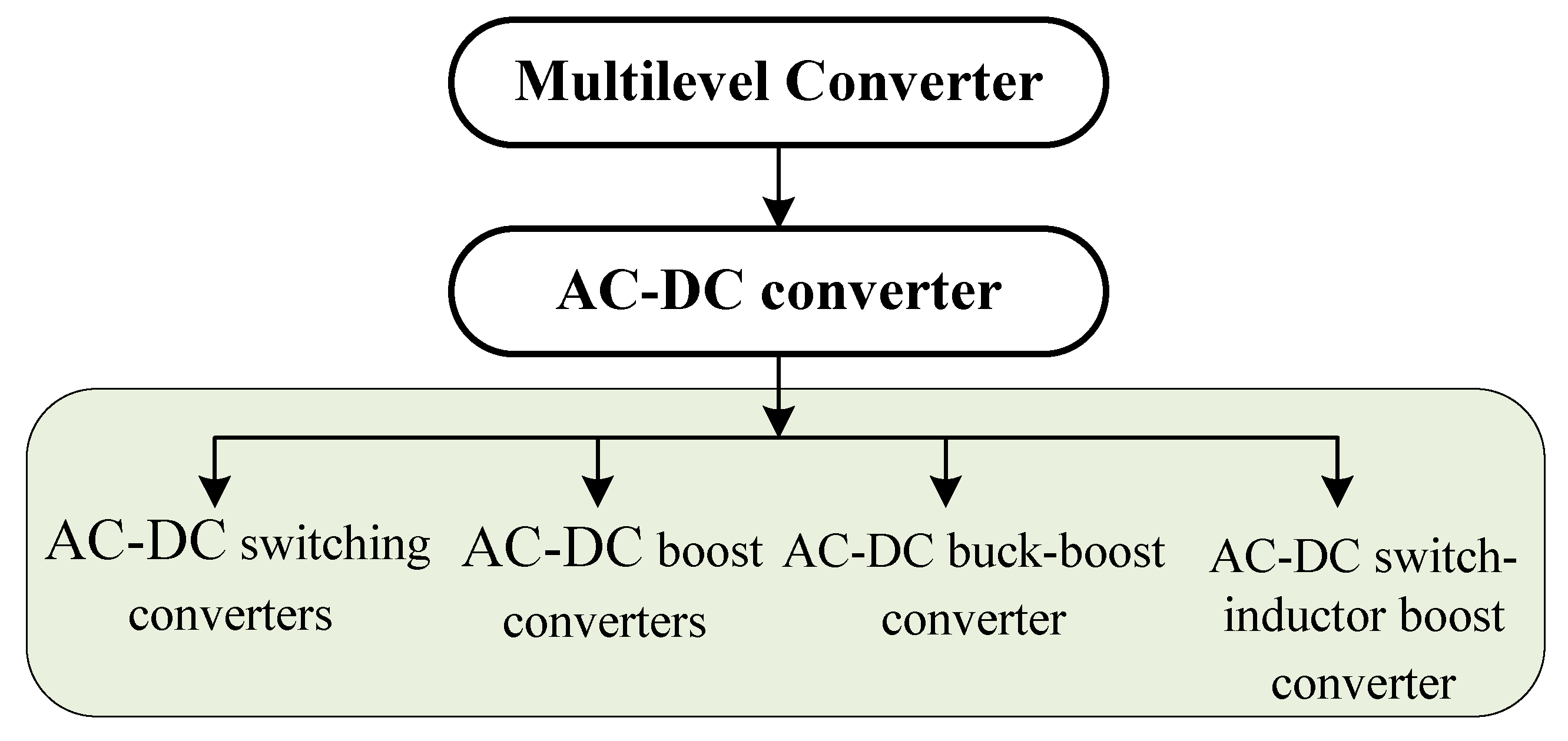
4.2. Converter Technology for Electromagnetic Energy Harvesting System
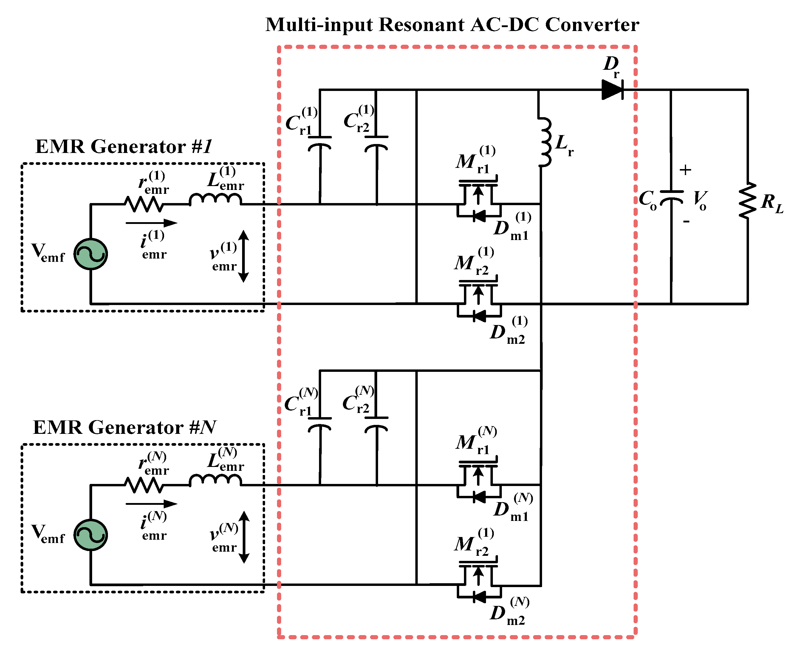
4.2.1. AC to DC Converter
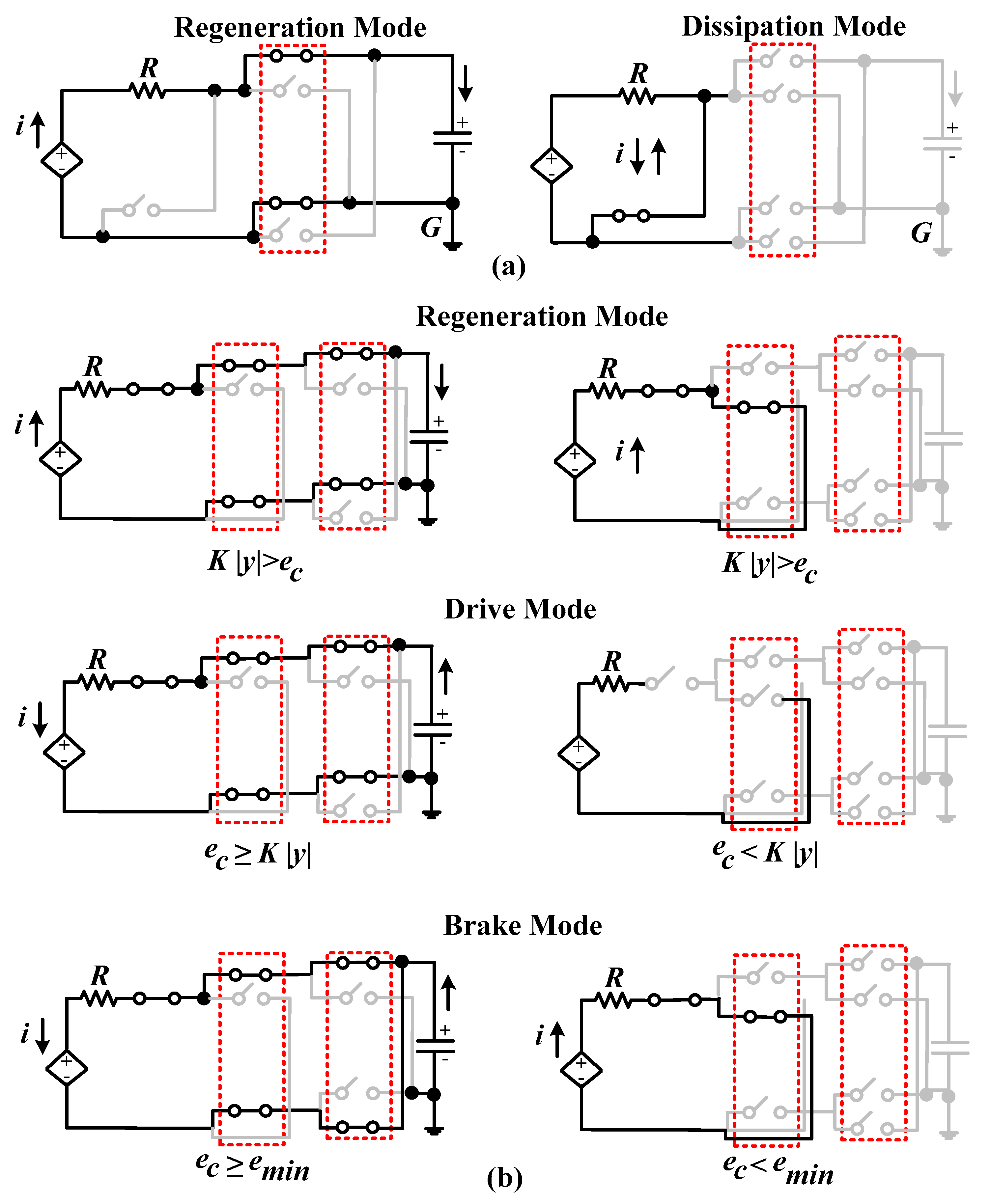
4.2.2. AC to DC Switching Converter
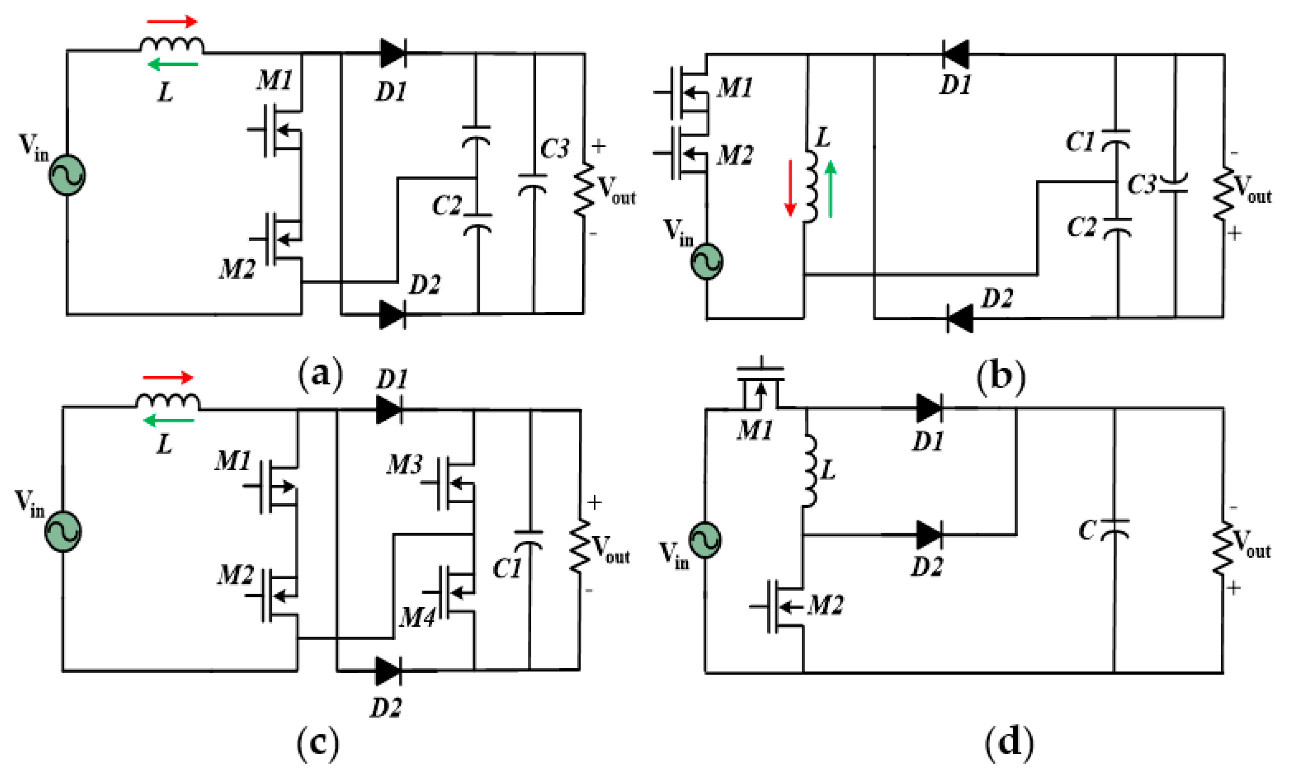
4.2.3. AC to DC Boost and Buck–Boost Converter
4.2.4. AC to DC Switch-Inductor Boost Converter
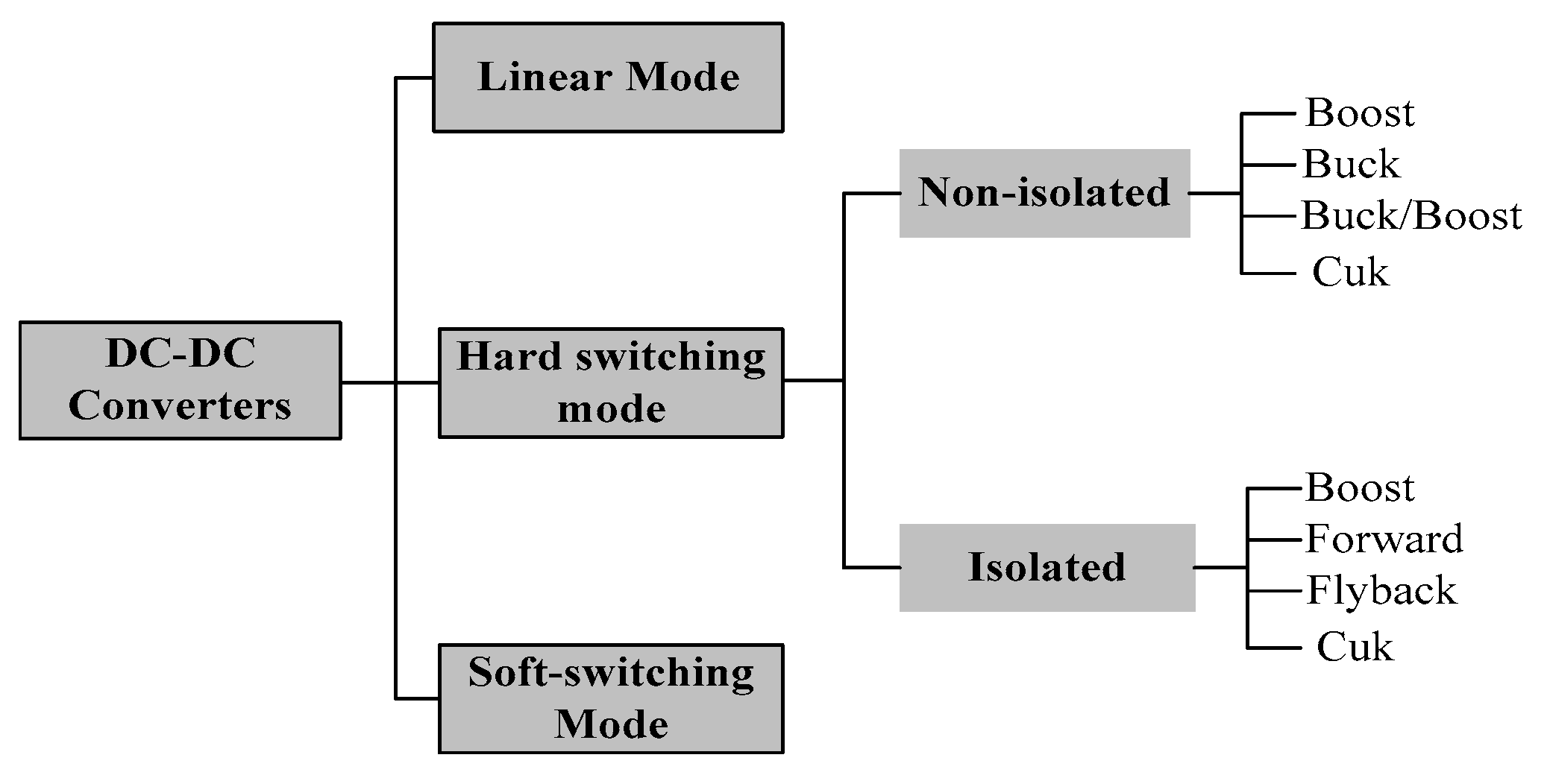
4.2.5. DC to DC Converter
5. Overview of Electromagnetic Energy Harvesting Techniques and Prototypes
5.1. Electromagnetic Energy Harvester Devices
5.2. Other Related Works on Electromagnetic Energy Harvesters Devices
6. Issues and Challenges
7. Conclusions and Recommendations
- More studies should be carried to improve energy density, power efficiency, and low resonance frequency for EMEH deceives.
- A switching device with the PWM technique can control the power in AC-DC converters but reduces the power factor and adds harmonics, which can be avoided by a low pass filter and PWM switch. Whereas, in a DC-DC converter for power factor improvement, a power factor correction capacitor is a good option.
- With regards to gaining accurate system performance and market acceptance, security, flexibility, long life, and stability problems of the EH transducer need to be addressed.
- Optimization techniques can be utilized to get the optimal parameter geometry shape of the EMEH devices such as length, width, and thickness.
- An intelligent real-time interface controller board can be performed to implement the EMEH circuit prototype for the robust, smart, and efficient converter, controller, and inverter.
- It is important to address a capable energy storage scheme such as supercapacitor charging/discharging, protection, reliability, scale, expense, life cycle, and overall management.
- Further research on the power, safety, control interface, energy management, and features of an advanced EMEH device are needed to improve the efficiency of energy storage in EH applications.
Author Contributions
Funding
Conflicts of Interest
References
- Bo, L.D.; Gardonio, P.; Turco, E. Analysis and scaling study of vibration energy harvesting with reactive electromagnetic and piezoelectric transducers. J. Sound Vib. 2020, 484, 115510. [Google Scholar] [CrossRef]
- Kim, J. A Study on the Analytic Power Estimation of the Electromagnetic Resonant Energy Harvester for the High-Speed Train. Electronics 2020, 9, 403. [Google Scholar] [CrossRef] [Green Version]
- Wu, Z.; Tang, J.; Zhang, X.; Yu, Z. An energy harvesting bracelet. Appl. Phys. Lett. 2017, 111, 013903. [Google Scholar] [CrossRef]
- Sarker, M.R.; Julai, S.; Sabri, M.F.M.; Said, S.M.; Islam, M.; Tahir, M. Review of piezoelectric energy harvesting system and application of optimization techniques to enhance the performance of the harvesting system. Sens. Actuators A Phys. 2019, 300, 111634. [Google Scholar] [CrossRef]
- Moghe, R.; Yang, Y.; Lambert, F.; Divan, D. A scoping study of electric and magnetic field energy harvesting for wireless sensor networks in power system applications. In Proceedings of the 2009 IEEE Energy Conversion Congress and Exposition, San Jose, CA, USA, 20–24 September 2009; pp. 3550–3557. [Google Scholar]
- Grossi, M. Energy Harvesting Strategies for Wireless Sensor Networks and Mobile Devices: A Review. Electronics 2021, 10, 661. [Google Scholar] [CrossRef]
- Jiao, D.; Ke, L.; Liu, S.; Chan, F.T. Optimal Energy-Delay in Energy Harvesting Wireless Sensor Networks with Interference Channels. Sensors 2019, 19, 785. [Google Scholar] [CrossRef] [PubMed] [Green Version]
- Wang, H.; Li, W.; Xu, D.; Kan, J. A Hybrid Microenergy Storage System for Power Supply of Forest Wireless Sensor Nodes. Electronics 2019, 8, 1409. [Google Scholar] [CrossRef] [Green Version]
- Li, Y.; Hamed, E.A.; Zhang, X.; Luna, D.; Lin, J.-S.; Liang, X.; Lee, I. Feasibility of Harvesting Solar Energy for Self-Powered Environmental Wireless Sensor Nodes. Electronics 2020, 9, 2058. [Google Scholar] [CrossRef]
- Sarker, M.R.; Mohamed, R.; Saad, M.H.M.; Tahir, M.; Hussain, A.; Mohamed, A. A Hybrid Optimization Approach for the Enhancement of Efficiency of a Piezoelectric Energy Harvesting System. Electronics 2021, 10, 75. [Google Scholar] [CrossRef]
- Banerjee, S.; Bairagi, S.; Ali, S.W. A critical review on lead-free hybrid materials for next generation piezoelectric energy harvesting and conversion. Ceram. Int. 2021, 47, 16402–16421. [Google Scholar] [CrossRef]
- Wang, Z.L.; Song, J. Piezoelectric nanogenerators based on zinc oxide nanowire arrays. Science 2006, 312, 242–246. [Google Scholar] [CrossRef]
- Zhao, L.; Duan, J.; Liu, L.; Wang, J.; Duan, Y.; Vaillant-Roca, L.; Yang, X.; Tang, Q. Boosting power conversion efficiency by hybrid triboelectric nanogenerator/silicon tandem solar cell toward rain energy harvesting. Nano Energy 2021, 82, 105773. [Google Scholar] [CrossRef]
- Shakeel, M.; Rehman, K.; Ahmad, S.; Amin, M.; Iqbal, N.; Khan, A. A low-cost printed organic thermoelectric generator for low-temperature energy harvesting. Renew. Energy 2020, 167, 853–860. [Google Scholar] [CrossRef]
- Li, X.; Li, Z.; Bi, C.; Liu, B.; Su, Y. Study on Wind Energy Harvesting Effect of a Vehicle-Mounted Piezo-Electromagnetic Hybrid Energy Harvester. IEEE Access 2020, 8, 167631–167646. [Google Scholar] [CrossRef]
- Ghany, A.; Shehata, E.; Elsayed, A.-H.; Mohamed, Y.; Alhelou, H.H.; Siano, P.; Diab, A. Novel Switching Frequency FCS-MPC of PMSG for Grid-Connected Wind Energy Conversion System with Coordinated Low Voltage Ride Through. Electronics 2021, 10, 492. [Google Scholar] [CrossRef]
- Bakytbekov, A.; Nguyen, T.Q.; Li, W.; Cottrill, A.L.; Zhang, G.; Strano, M.S.; Salama, K.N.; Shamim, A. Multi-source ambient energy harvester based on RF and thermal energy: Design, testing, and IoT application. Energy Sci. Eng. 2020, 8, 3883–3897. [Google Scholar] [CrossRef]
- Gholikhani, M.; Shirazi, S.Y.B.; Mabrouk, G.M.; Dessouky, S. Dual electromagnetic energy harvesting technology for sustainable transportation systems. Energy Convers. Manag. 2021, 230, 113804. [Google Scholar] [CrossRef]
- Falk, M.; Shleev, S. Hybrid dual-functioning electrodes for combined ambient energy harvesting and charge storage: Towards self-powered systems. Biosens. Bioelectron. 2019, 126, 275–291. [Google Scholar] [CrossRef]
- Tang, X.; Wang, X.; Cattley, R.; Gu, F.; Ball, A.D. Energy Harvesting Technologies for Achieving Self-Powered Wireless Sensor Networks in Machine Condition Monitoring: A Review. Sensors 2018, 18, 4113. [Google Scholar] [CrossRef] [PubMed] [Green Version]
- Chamanian, S.; Uluşan, H.; Zorlu, Ö.; Baghaee, S.; Uysal-Biyikoglu, E.; Külah, H. Wearable battery-less wireless sensor network with electromagnetic energy harvesting system. Sens. Actuators A Phys. 2016, 249, 77–84. [Google Scholar] [CrossRef]
- Hu, Z.; Liu, Q.; Chou, S.-L.; Dou, S.-X. Two-Dimensional Material-Based Heterostructures for Rechargeable Batteries. Cell Rep. Phys. Sci. 2021, 2, 100286. [Google Scholar] [CrossRef]
- Li, Z.; Luo, J.; Xie, S.; Xin, L.; Guo, H.; Pu, H.; Yin, P.; Xu, Z.; Zhang, D.; Peng, Y.; et al. Instantaneous peak 2.1 W-level hybrid energy harvesting from human motions for self-charging battery-powered electronics. Nano Energy 2021, 81, 105629. [Google Scholar] [CrossRef]
- Ma, J.; Shang, P.; Zou, X.; Ma, N.; Ding, Y.; Sun, J.; Cheng, Y.; Tao, L.; Lu, C.; Su, Y.; et al. A hybrid transfer learning scheme for remaining useful life prediction and cycle life test optimization of different formulation Li-ion power batteries. Appl. Energy 2021, 282, 116167. [Google Scholar] [CrossRef]
- Alghisi, D.; Ferrari, V.; Crescini, D.; Touati, F.; Ben Mnaouer, A.B. Single- and multi-source battery-less power management circuits for piezoelectric energy harvesting systems. Sens. Actuators A Phys. 2017, 264, 234–246. [Google Scholar] [CrossRef]
- Sherazi, H.H.R.; Grieco, L.A.; Boggia, G. A comprehensive review on energy harvesting MAC protocols in WSNs: Challenges and tradeoffs. Ad Hoc Netw. 2018, 71, 117–134. [Google Scholar] [CrossRef]
- Antonopoulos, C.P.; Voros, N.S. Resource efficient data compression algorithms for demanding, WSN based biomedical applications. J. Biomed. Inform. 2016, 59, 1–14. [Google Scholar] [CrossRef] [Green Version]
- Li, K.; He, X.; Wang, X.; Jiang, S. A Nonlinear Electromagnetic Energy Harvesting System for Self-Powered Wireless Sensor Nodes. J. Sens. Actuator Netw. 2019, 8, 18. [Google Scholar] [CrossRef] [Green Version]
- Izhar; Khan, F.U. Electromagnetic based acoustic energy harvester for low power wireless autonomous sensor applications. Sens. Rev. 2018, 38, 298–310. [Google Scholar] [CrossRef]
- Kubba, A.E.; Jiang, K. A Comprehensive Study on Technologies of Tyre Monitoring Systems and Possible Energy Solutions. Sensors 2014, 14, 10306–10345. [Google Scholar] [CrossRef] [PubMed]
- Amirtharajah, R.; Chandrakasan, A. Self-powered signal processing using vibration-based power generation. IEEE J. Solid-State Circuits 1998, 33, 687–695. [Google Scholar] [CrossRef] [Green Version]
- Xu, Y.; Ha, D.S.; Xu, M. Energy harvesting circuit with input matching in boundary conduction mode for electromagnetic generators. In Proceedings of the 2017 IEEE International Symposium on Circuits and Systems (ISCAS), Baltimore, MD, USA, 28–31 May 2017; pp. 1–4. [Google Scholar]
- Gu, Y.; Liu, W.; Zhao, C.; Wang, P. A goblet-like non-linear electromagnetic generator for planar multi-directional vibration energy harvesting. Appl. Energy 2020, 266, 114846. [Google Scholar] [CrossRef]
- Kakou, P.; Barry, O. Simultaneous vibration reduction and energy harvesting of a nonlinear oscillator using a nonlinear electromagnetic vibration absorber-inerter. Mech. Syst. Signal. Process. 2021, 156, 107607. [Google Scholar] [CrossRef]
- Rahman, M.T.; Rana, S.S.; Salauddin, M.; Maharjan, P.; Bhatta, T.; Kim, H.; Cho, H.; Park, J.Y. A highly miniaturized freestanding kinetic-impact-based non-resonant hybridized electromagnetic-triboelectric nanogenerator for human induced vibrations harvesting. Appl. Energy 2020, 279, 115799. [Google Scholar] [CrossRef]
- He, J.; Fan, X.; Mu, J.; Wang, C.; Qian, J.; Li, X.; Hou, X.; Geng, W.; Wang, X.; Chou, X. 3D full-space triboelectric-electromagnetic hybrid nanogenerator for high-efficient mechanical energy harvesting in vibration system. Energy 2020, 194, 116871. [Google Scholar] [CrossRef]
- Li, Z.; Liu, Y.; Yin, P.; Peng, Y.; Luo, J.; Xie, S.; Pu, H. Constituting abrupt magnetic flux density change for power density improvement in electromagnetic energy harvesting. Int. J. Mech. Sci. 2021, 198, 106363. [Google Scholar] [CrossRef]
- Chen, J.; Peng, H.; Feng, Z.; Chen, Y.; Zeng, C.; Kang, Y. A Fully PCB Integrated Self-Powered Micro Generator for Vibration Electromagnetic Harvesting. In Proceedings of the 2020 IEEE Applied Power Electronics Conference Exposition (APEC), New Orleans, LA, USA, 15–19 March 2020; pp. 3594–3599. [Google Scholar]
- Siddique, A.R.M.; Mahmud, S.; Heyst, B.v. A comprehensive review on vibration based micro power generators using electromagnetic and piezoelectric transducer mechanisms. Energy Convers. Manag. 2015, 106, 728–747. [Google Scholar] [CrossRef]
- Iqbal, M.; Khan, F.U.; Mehdi, M.; Cheok, Q.; Abas, E.; Nauman, M.M. Power harvesting footwear based on piezo-electromagnetic hybrid generator for sustainable wearable microelectronics. J. King Saud Univ. Eng. Sci. 2020. [Google Scholar] [CrossRef]
- Chae, S.H.; Ju, S.; Choi, Y.; Chi, Y.-E.; Ji, C.-H. Electromagnetic Linear Vibration Energy Harvester Using Sliding Permanent Magnet Array and Ferrofluid as a Lubricant. Micromachines 2017, 8, 288. [Google Scholar] [CrossRef] [PubMed] [Green Version]
- Cho, S.J.; Kim, J.H. Linear electromagnetic electric generator for harvesting vibration energy at frequencies more than 50 Hz. Adv. Mech. Eng. 2017, 9, 168781401771900. [Google Scholar] [CrossRef]
- Yan, B.; Wang, Z.; Ma, H.; Bao, H.; Wang, K.; Wu, C. A novel lever-type vibration isolator with eddy current damping. J. Sound Vib. 2021, 494, 115862. [Google Scholar] [CrossRef]
- Parekh, M.; Magnusson, J.; Engdahl, G. Study of an Electromagnetic Damping Actuator-VDE Conference Publication. In Proceedings of the ACTUATOR 2018; 16th International Conference on New Actuators, Bremen, Germany, 25–27 June 2018. [Google Scholar]
- Li, S.; Xu, J.; Pu, X.; Tao, T.; Gao, H.; Mei, X. Energy-harvesting variable/constant damping suspension system with motor based electromagnetic damper. Energy 2019, 189, 116199. [Google Scholar] [CrossRef]
- Pan, Q.; He, T.; Xiao, D.; Liu, X. Design and Damping Analysis of a New Eddy Current Damper for Aerospace Applications. Lat. Am. J. Solids Struct. 2016, 13, 1997–2011. [Google Scholar] [CrossRef] [Green Version]
- Pei, Y.; Liu, Y.; Zuo, L. Multi-resonant electromagnetic shunt in base isolation for vibration damping and energy harvesting. J. Sound Vib. 2018, 423, 1–17. [Google Scholar] [CrossRef] [Green Version]
- Kiziroglou, M.; Wright, S.; Yeatman, E. Coil and core design for inductive energy receivers. Sens. Actuators A Phys. 2020, 313, 112206. [Google Scholar] [CrossRef]
- Han, Q.; Ding, Z.; Sun, W.; Xu, X.; Chu, F. Hybrid triboelectric-electromagnetic generator for self-powered wind speed and direction detection. Sustain. Energy Technol. Assess. 2020, 39, 100717. [Google Scholar] [CrossRef]
- Yen, K.T. Energy Harvesting Autonomous Sensor Systems: Design, Analysis, and Practical Implementation; CRC Press: Boca Raton, FL, USA, 2013; ISBN 9781138074095. [Google Scholar]
- Penella-López, M.T.; Gasulla-Forner, M.; Penella-López, M.T.; Gasulla-Forner, M. Powering Autonomous Sensors; Springer: Dordrecht, The Netherlands, 2011; pp. 1–7. [Google Scholar]
- Kalaivaani, P.; Krishnamoorthi, R. Design and implementation of low power bio signal sensors for wireless body sensing network applications. Microprocess. Microsyst. 2020, 79, 103271. [Google Scholar] [CrossRef]
- Mahmood, M.F.; Mohammed, S.L.; Gharghan, S.K.; Al-Naji, A.; Chahl, J. Hybrid Coils-Based Wireless Power Transfer for Intelligent Sensors. Sensors 2020, 20, 2549. [Google Scholar] [CrossRef]
- Landaluce, H.; Arjona, L.; Perallos, A.; Falcone, F.; Angulo, I.; Muralter, F. A Review of IoT Sensing Applications and Challenges Using RFID and Wireless Sensor Networks. Sensors 2020, 20, 2495. [Google Scholar] [CrossRef]
- Sunny, A.I.; Zhao, A.; Li, L.; Kanteh Sakiliba, S.K. Low-Cost IoT-Based Sensor System: A Case Study on Harsh Environmental Monitoring. Sensors 2020, 21, 214. [Google Scholar] [CrossRef]
- DeLuca, M.; Köck, A. Current Perspectives for Autonomous Sensor Nodes. Proceedings 2020, 56, 7. [Google Scholar] [CrossRef]
- Tholl, M.; Akarçay, H.; Tanner, H.; Niederhauser, T.; Zurbuchen, A.; Frenz, M.; Haeberlin, A. Subdermal solar energy harvesting—A new way to power autonomous electric implants. Appl. Energy 2020, 269, 114948. [Google Scholar] [CrossRef]
- Szarka, G.D.; Stark, B.H.; Burrow, S.G. Review of Power Conditioning for Kinetic Energy Harvesting Systems. IEEE Trans. Power Electron. 2011, 27, 803–815. [Google Scholar] [CrossRef]
- Wu, Z.; Cheng, T.; Wang, Z.L. Self-Powered Sensors and Systems Based on Nanogenerators. Sensors 2020, 20, 2925. [Google Scholar] [CrossRef] [PubMed]
- Wang, Z.L. Energy harvesting for self-powered nanosystems. Nano Res. 2008, 1, 1–8. [Google Scholar] [CrossRef] [Green Version]
- Wu, Z.; Wen, Y.; Li, P. A Power Supply of Self-Powered Online Monitoring Systems for Power Cords. IEEE Trans. Energy Convers. 2013, 28, 921–928. [Google Scholar] [CrossRef]
- Khan, S.A.; Rajkumar, R.K.; Wan, W.Y.; Syed, A. Supercapacitor-Based Hybrid Energy Harvesting for Low-Voltage System. In Supercapacitors—Theoretical and Practical Solutions; IntechOpen: London, UK, 2018. [Google Scholar]
- Yin, J.; Wen, Z.; Yu, J.; Shi, X.; Wang, G.; Yang, Y.-E.; Man, J.; Sun, J.; Cui, L. Self-templated hierarchical TiO2@C microrods with synergic battery/capacitor hybrid energy storage: Toward ultra-long cycling life and outstanding rate performance. J. Alloys Compd. 2019, 808, 151728. [Google Scholar] [CrossRef]
- Chan, K.-Y.; Pham, D.Q.; Demir, B.; Yang, D.; Mayes, E.L.; Mouritz, A.P.; Ang, A.S.; Fox, B.; Lin, H.; Jia, B.; et al. Graphene oxide thin film structural dielectric capacitors for aviation static electricity harvesting and storage. Compos. Part B Eng. 2020, 201, 108375. [Google Scholar] [CrossRef]
- Deka, B.K.; Hazarika, A.; Lee, S.; Kim, D.Y.; Park, Y.-B.; Park, H.W. Triboelectric-nanogenerator-integrated structural supercapacitor based on highly active P-doped branched Cu–Mn selenide nanowires for efficient energy harvesting and storage. Nano Energy 2020, 73, 104754. [Google Scholar] [CrossRef]
- Zhang, X.; Zhang, Z.; Pan, H.; Salman, W.; Yuan, Y.; Liu, Y. A portable high-efficiency electromagnetic energy harvesting system using supercapacitors for renewable energy applications in railroads. Energy Convers. Manag. 2016, 118, 287–294. [Google Scholar] [CrossRef]
- Bai, Y.; Muralidharan, N.; Sun, Y.-K.; Passerini, S.; Whittingham, M.S.; Belharouak, I. Energy and environmental aspects in recycling lithium-ion batteries: Concept of Battery Identity Global Passport. Mater. Today 2020, 41, 304–315. [Google Scholar] [CrossRef]
- Ahmed, F.; Kervadec, C.; Le Moullec, Y.; Tamberg, G.; Annus, P. Autonomous Wireless Sensor Networks: Implementation of Transient Computing and Energy Prediction for Improved Node Performance and Link Quality. Comput. J. 2018, 62, 820–837. [Google Scholar] [CrossRef]
- Nikolov, D.N.; Ganev, B.T.; Rusev, R.P. Energy harvesting power supply for an autonomous environmental sensor node. In Proceedings of the 2019 IEEE XXVIII International Scientific Conference Electronics (ET), Sozopol, Bulgaria, 12–14 September 2019; pp. 1–4. [Google Scholar]
- Jung, I.; Choi, J.; Park, H.-J.; Lee, T.-G.; Nahm, S.; Song, H.-C.; Kim, S.; Kang, C.-Y. Design principles for coupled piezoelectric and electromagnetic hybrid energy harvesters for autonomous sensor systems. Nano Energy 2020, 75, 104921. [Google Scholar] [CrossRef]
- Xu, Y.; Bader, S.; Magno, M.; Mayer, P.; Oelmann, B. Energy-autonomous On-rotor RPM Sensor Using Variable Reluctance Energy Harvesting. In Proceedings of the 2019 IEEE 8th International Workshop on Advances in Sensors and Interfaces (IWASI), Otranto, Italy, 13–14 June 2019; pp. 175–180. [Google Scholar]
- Fernando, A.S. Energy Harvesting for Autonomous Systems; IEEE: Piscataway, NJ, USA, 2012. [Google Scholar]
- Vu, H.S.; Nguyen, N.; Ha-Van, N.; Seo, C.; Le, M.T. Multiband Ambient RF Energy Harvesting for Autonomous IoT Devices. IEEE Microw. Wirel. Compon. Lett. 2020, 30, 1189–1192. [Google Scholar] [CrossRef]
- Saraereh, O.A.; Alsaraira, A.; Khan, I.; Choi, B.J. A Hybrid Energy Harvesting Design for On-Body Internet-of-Things (IoT) Networks. Sensors 2020, 20, 407. [Google Scholar] [CrossRef] [Green Version]
- Prauzek, M.; Konecny, J.; Borova, M.; Janosova, K.; Hlavica, J.; Musilek, P. Energy Harvesting Sources, Storage Devices and System Topologies for Environmental Wireless Sensor Networks: A Review. Sensors 2018, 18, 2446. [Google Scholar] [CrossRef] [PubMed] [Green Version]
- Liu, H.; Fu, H.; Sun, L.; Lee, C.; Yeatman, E.M. Hybrid energy harvesting technology: From materials, structural design, system integration to applications. Renew. Sustain. Energy Rev. 2021, 137, 110473. [Google Scholar] [CrossRef]
- Yang, F.; Du, L.; Chen, W.; Li, J.; Wang, Y.; Wang, D. Hybrid energy harvesting for condition monitoring sensors in power grids. Energy 2017, 118, 435–445. [Google Scholar] [CrossRef]
- Lau, D.; Song, N.; Hall, C.; Jiang, Y.; Lim, S.; Perez-Wurfl, I.; Ouyang, Z.; Lennon, A. Hybrid solar energy harvesting and storage devices: The promises and challenges. Mater. Today Energy 2019, 13, 22–44. [Google Scholar] [CrossRef]
- Zhu, M.; Lou, M.; Yu, J.; Li, Z.; Ding, B. Energy autonomous hybrid electronic skin with multi-modal sensing capabilities. Nano Energy 2020, 78, 105208. [Google Scholar] [CrossRef]
- Etim, N.-B.B.; Giaouris, D.; Papadopoulos, A.I.; Patsios, H.; Papadopoulou, S.; Voutetakis, S.; Seferlis, P.; Walker, S.; Taylor, P.; Gadoue, S. Adaptive Power Pinch Analysis for Energy management of Hybrid Energy Storage Systems. In Proceedings of the 2018 IEEE International Symposium on Circuits and Systems (ISCAS), Florence, Italy, 27–30 May 2018; pp. 1–5. [Google Scholar]
- Francesco, O. Disadvantages and Advantages of Energy Harvesting; Technical Articles; All About Circuits: Boise, ID, USA, 2019. [Google Scholar]
- Chamanian, S.; Ciftci, B.; Ulusan, H.; Muhtaroglu, A.; Kulah, H. Power-Efficient Hybrid Energy Harvesting System for Harnessing Ambient Vibrations. IEEE Trans. Circuits Syst. I Regul. Pap. 2019, 66, 2784–2793. [Google Scholar] [CrossRef]
- Ramírez, J.; Gatti, C.; Machado, S.; Febbo, M. Energy harvesting for autonomous thermal sensing using a linked E-shape multi-beam piezoelectric device in a low frequency rotational motion. Mech. Syst. Signal. Process. 2019, 133, 106267. [Google Scholar] [CrossRef]
- Zhang, X.; Grajal, J.; López-Vallejo, M.; McVay, E.; Palacios, T. Opportunities and Challenges of Ambient Radio-Frequency Energy Harvesting. Joule 2020, 4, 1148–1152. [Google Scholar] [CrossRef]
- Martins, G.C.; Mansano, A.L.; Stoopman, M.; Serdijn, W.A. Introduction to RF energy harvesting. In Wearable Sensors; Elsevier: Amsterdam, The Netherlands, 2021; pp. 311–336. [Google Scholar]
- Mouapi, A.; Hakem, N.; Delisle, G.Y. A new approach to design of RF energy harvesting system to enslave wireless sensor networks. ICT Express 2018, 4, 228–233. [Google Scholar] [CrossRef]
- Tan, G.P.; Bautista, J.J.P. Utilization of low cost RF harvester circuit in harnessing electrical energy from multiband RF signals. In Proceedings of the 2017 Asian Conference on Energy, Power and Transportation Electrification (ACEPT), Singapore, 24–26 October 2017; pp. 1–5. [Google Scholar]
- Li, J.; Xiong, K.; Cao, J.; Yang, X.; Liu, T. Energy Efficiency in RF Energy Harvesting-Powered Distributed Antenna Systems for the Internet of Things. Sensors 2020, 20, 4631. [Google Scholar] [CrossRef] [PubMed]
- Sarker, M.R.; Mohamed, R.; Saad, M.H.M.; Mohamed, A. dSPACE Controller-Based Enhanced Piezoelectric Energy Harvesting System Using PI-Lightning Search Algorithm. IEEE Access 2018, 7, 3610–3626. [Google Scholar] [CrossRef]
- Banguero, E.; Correcher, A.; Pérez-Navarro, Á.; Morant, F.; Aristizabal, A. A Review on Battery Charging and Discharging Control Strategies: Application to Renewable Energy Systems. Energies 2018, 11, 1021. [Google Scholar] [CrossRef] [Green Version]
- Gindullina, E.; Badia, L. Towards self-control of service rate for battery management in energy harvesting devices. In Proceedings of the 2017 IEEE International Conference on Communications Workshops (ICC Workshops), Paris, France, 21–25 May 2017; pp. 355–360. [Google Scholar]
- Walton, M.; Woods, J.; Zheng, G. Efficient charging for batteryless solutions in energy harvesting. In Proceedings of the 2019 11th Computer Science and Electronic Engineering (CEEC), Colchester, UK, 18–19 September 2019; pp. 7–11. [Google Scholar]
- Pozo, B.; Garate, J.I.; Araujo, J.A.; Ferreiro, S. Energy Harvesting Technologies and Equivalent Electronic Structural Models—Review. Electronics 2019, 8, 486. [Google Scholar] [CrossRef] [Green Version]
- Yang, F.; Du, L.; Yu, H.; Huang, P. Magnetic and Electric Energy Harvesting Technologies in Power Grids: A Review. Sensors 2020, 20, 1496. [Google Scholar] [CrossRef] [Green Version]
- Shen, Y.; Lu, K. Scavenging power from ultra-low frequency and large amplitude vibration source through a new non-resonant electromagnetic energy harvester. Energy Convers. Manag. 2020, 222, 113233. [Google Scholar] [CrossRef]
- Bolt, R.; Magno, M.; Burger, T.; Romani, A.; Benini, L. Kinetic AC/DC Converter for Electromagnetic Energy Harvesting in Autonomous Wearable Devices. IEEE Trans. Circuits Syst. II Express Briefs 2017, 64, 1422–1426. [Google Scholar] [CrossRef]
- Yekta, H.B.; Fakhari, V. Nonlinear modeling, design and parametric study of an effective harvester in large amplitude vibration using magnetoelectric transducer. J. Magn. Magn. Mater. 2021, 519, 167419. [Google Scholar] [CrossRef]
- Liu, K.; Chen, M.; Gong, Y.; Fan, S.; Wang, G. A 100 μW AC-DC Boost Converter for Electromagnetic Energy Harvesting with 0.2 V Peak Self-starting Voltage and 85% Efficiency. In Proceedings of the 2018 IEEE Asia Pacific Conference on Circuits and Systems (APCCAS), Chengdu, China, 26–30 October 2019; pp. 493–496. [Google Scholar]
- Bo, L.D.; Gardonio, P. Energy harvesting with electromagnetic and piezoelectric seismic transducers: Unified theory and experimental validation. J. Sound Vib. 2018, 433, 385–424. [Google Scholar] [CrossRef]
- Lallart, M.; Lombardi, G. Synchronized Switch Harvesting on ElectroMagnetic System: A nonlinear technique for hybrid energy harvesting based on active inductance. Energy Convers. Manag. 2020, 203, 112135. [Google Scholar] [CrossRef]
- Loong, C.N.; Chang, C.-C.; Dimitrakopoulos, E.G. Circuit nonlinearity effect on the performance of an electromagnetic energy harvester-structure system. Eng. Struct. 2018, 173, 449–459. [Google Scholar] [CrossRef]
- Ma, H.; Yan, B. Nonlinear damping and mass effects of electromagnetic shunt damping for enhanced nonlinear vibration isolation. Mech. Syst. Signal. Process. 2021, 146, 107010. [Google Scholar] [CrossRef]
- Moon, J.; Leeb, S.B. Power Electronic Circuits for Magnetic Energy Harvesters. IEEE Trans. Power Electron. 2015, 31, 270–279. [Google Scholar] [CrossRef]
- Asai, T.; Araki, Y.; Ikago, K. Energy harvesting potential of tuned inertial mass electromagnetic transducers. Mech. Syst. Signal. Process. 2017, 84, 659–672. [Google Scholar] [CrossRef] [Green Version]
- Filho, M.J.; De Vasconcellos, R.M.G.; Ferreira, A.A. Design and Optimization of Electromagnetic Transducer for Aeroelastic Energy Harvesting. In Proceedings of the 2019 4th International Symposium on Instrumentation Systems, Circuits and Transducers (INSCIT), Sao Paulo, Brazil, 26–30 August 2019; pp. 1–5. [Google Scholar]
- Cai, Q.; Zhu, S. Unified strategy for overall impedance optimization in vibration-based electromagnetic energy harvesters. Int. J. Mech. Sci. 2020, 165, 105198. [Google Scholar] [CrossRef]
- Wang, J.; Dancy, A.J.; Ha, D.S. Vibration Energy Harvesting Circuit with Impedance Matching and Wake-up for Freight Railcars. In Proceedings of the IECON 2018—44th Annual Conference of the IEEE Industrial Electronics Society, Washington, DC, USA, 21–23 October 2018; pp. 1975–1979. [Google Scholar]
- Dancy, A.J.; Li, J.; Ha, D.S. Split-Capacitor Boost Converter Operating in Boundary Conduction Mode with Impedance Matching for Kinetic Energy Harvesting. In Proceedings of the 2020 IEEE 63rd International Midwest Symposium on Circuits and Systems (MWSCAS), Springfield, MA, USA, 9–12 August 2020; pp. 203–207. [Google Scholar]
- Chen, J.; Peng, H.; Feng, Z.; Kang, Y. A GaN BCM AC-DC Converter for Sub-1V Electromagnetic Energy Harvesting with Enhanced Output Power. IEEE Trans. Power Electron. 2021, 1. [Google Scholar] [CrossRef]
- Tehrani, S.Z.; Ranjbar, H.; Vial, P.; Premaratne, P. A New Efficient Power Management Interface for Hybrid Electromagnetic-Piezoelectric Energy Harvesting System. In 16th International Conference on Information; Springer: Cham, Switzerland, 2019; Volume 800, pp. 537–542. [Google Scholar]
- Balato, M.; Costanzo, L.; Vitelli, M. Resonant electromagnetic vibration harvesters: Determination of the equivalent electric circuit parameters and simplified closed-form analysis for the identification of the optimal diode bridge rectifier DC load. Int. J. Electr. Power Energy Syst. 2017, 84, 111–123. [Google Scholar] [CrossRef]
- Rodriguez, J.C.; Nico, V.; Punch, J. A Vibration Energy Harvester and Power Management Solution for Battery-Free Operation of Wireless Sensor Nodes. Sensors 2019, 19, 3776. [Google Scholar] [CrossRef] [Green Version]
- Pahlavandust, M.; Yazdani, M.R. Single-switch boost DC-DC converter with zero-current-switching, high power density and low electromagnetic interference. AEU Int. J. Electron. Commun. 2020, 121, 153229. [Google Scholar] [CrossRef]
- Paul, S.; Lee, D.; Kim, K.; Chang, J. Nonlinear modeling and performance testing of high-power electromagnetic energy harvesting system for self-powering transmission line vibration deicing robot. Mech. Syst. Signal. Process. 2021, 151, 107369. [Google Scholar] [CrossRef]
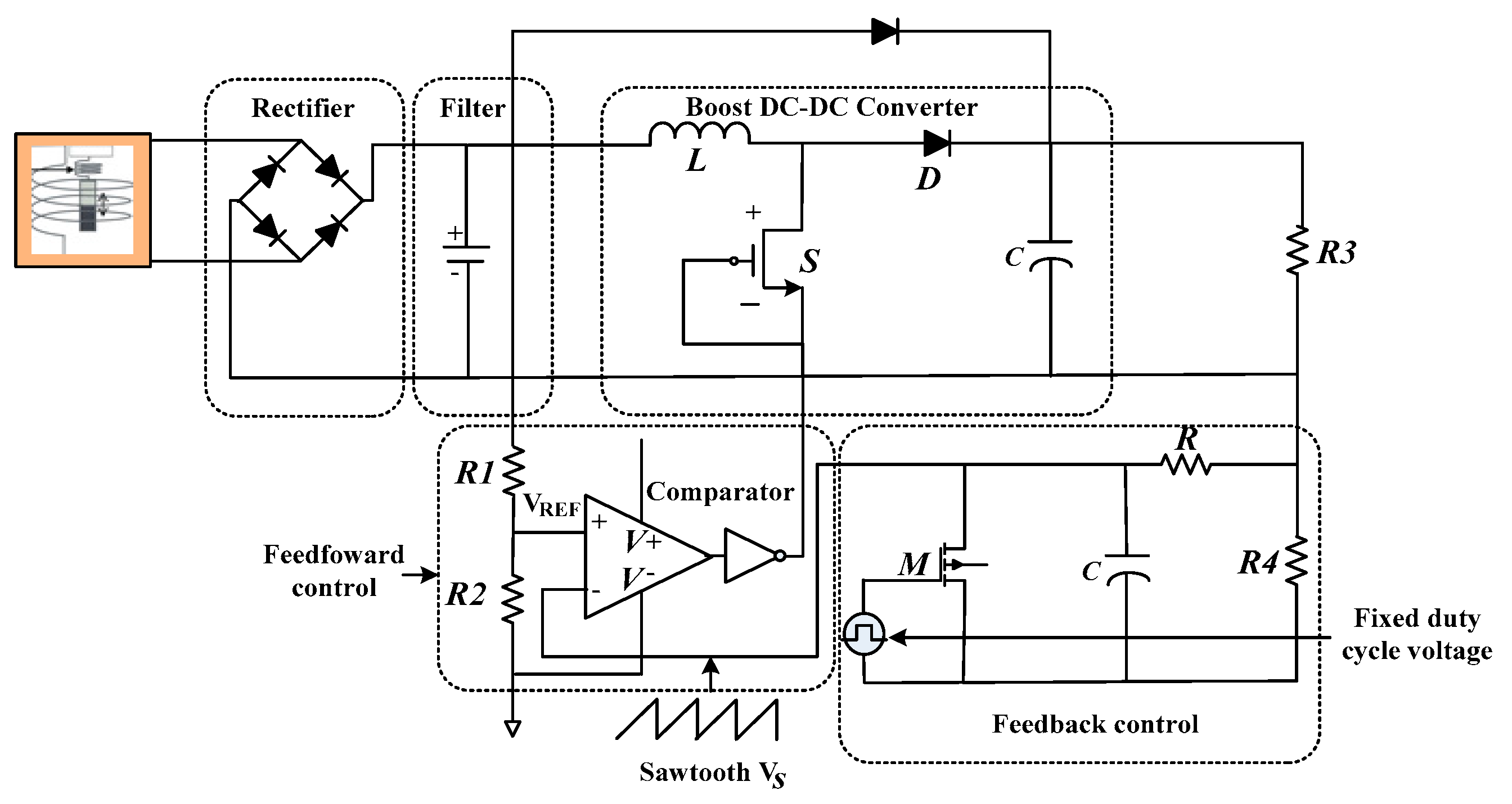
- Cao, X.; Chiang, W.-J.; King, Y.-C.; Lee, Y.-K. Electromagnetic Energy Harvesting Circuit with Feedforward and Feedback DC–DC PWM Boost Converter for Vibration Power Generator System. IEEE Trans. Power Electron. 2007, 22, 679–685. [Google Scholar] [CrossRef] [Green Version]
- Proynov, P.P.; Szarka, G.D.; Stark, B.H.; McNeill, N. Resistive matching with a feed-forward controlled non-synchronous boost rectifier for electromagnetic energy harvesting. In Proceedings of the 2013 Twenty-Eighth Annual IEEE Applied Power Electronics Conference and Exposition (APEC), Long Beach, CA, USA, 17–21 March 2013; pp. 3081–3086. [Google Scholar]
- Huang, T.-C.; Leu, Y.-G.; Huang, C.-W. Powering IoTs with a feedforward quasi universal boost converter energy harvester. Energy 2017, 133, 879–886. [Google Scholar] [CrossRef]
- Wang, X.; Liang, X.; Wei, H. A study of electromagnetic vibration energy harvesters with different interface circuits. Mech. Syst. Signal. Process. 2015, 58–59, 376–398. [Google Scholar] [CrossRef]
- Dong, X.; Huang, X. A Non-Resonant Type Electromagnetic Energy Harvester for Scavenging Vibration Energy. In Proceedings of the 2018 IEEE Sensors Applications Symposium (SAS), New Delhi, India, 28–31 October 2018; pp. 1–3. [Google Scholar]
- Arroyo, E.; Badel, A. Electromagnetic vibration energy harvesting device optimization by synchronous energy extraction. Sens. Actuators A Phys. 2011, 171, 266–273. [Google Scholar] [CrossRef]
- Xie, L.; Li, J.; Cai, S.; Li, X. Electromagnetic Energy-Harvesting Damper With Multiple Independently Controlled Transducers: On-Demand Damping and Optimal Energy Regeneration. IEEE/ASME Trans. Mechatron. 2017, 22, 2705–2713. [Google Scholar] [CrossRef]
- Thomas, S.; Reynolds, M.; Teizer, J. Electromagnetic Energy Harvesting for Sensing, Communication, and Actuation. In Proceedings of the 27th International Symposium on Automation and Robotics in Construction, Bratislava, Slovakia, 25–27 June 2010; pp. 183–192. [Google Scholar]
- Cai, Q.-L.; Zhu, S. Enhancing the performance of electromagnetic damper cum energy harvester using microcontroller: Concept and experiment validation. Mech. Syst. Signal. Process. 2019, 134, 106339. [Google Scholar] [CrossRef]
- Shen, W.; Zhu, S.; Zhu, H. Experimental study on using electromagnetic devices on bridge stay cables for simultaneous energy harvesting and vibration damping. Smart Mater. Struct. 2016, 25, 065011. [Google Scholar] [CrossRef]
- Peigney, M.; Siegert, D. Low-Frequency Electromagnetic Energy Harvesting from Highway Bridge Vibrations. J. Bridg. Eng. 2020, 25, 04020056. [Google Scholar] [CrossRef]
- Wang, X.; Liang, X.; Hao, Z.; Du, H.; Zhang, N.; Qian, M. Comparison of electromagnetic and piezoelectric vibration energy harvesters with different interface circuits. Mech. Syst. Signal. Process. 2016, 72–73, 906–924. [Google Scholar] [CrossRef]
- Hasheminejad, S.M.; Rabiee, A.H.; Markazi, A.H.D. Dual-Functional Electromagnetic Energy Harvesting and Vortex-Induced Vibration Control of an Elastically Mounted Circular Cylinder. J. Eng. Mech. 2018, 144, 04017184. [Google Scholar] [CrossRef]
- Zuo, L.; Cui, W. Dual-Functional Energy-Harvesting and Vibration Control: Electromagnetic Resonant Shunt Series Tuned Mass Dampers. J. Vib. Acoust. 2013, 135, 051018–0510189. [Google Scholar] [CrossRef] [PubMed] [Green Version]
- Rahimi, A.; Zorlu, Ö.; Muhtaroǧlu, A.; Külah, H. An electromagnetic energy harvesting system for low frequency applications with a passive interface ASIC in standard CMOS. Sens. Actuators A Phys. 2012, 188, 158–166. [Google Scholar] [CrossRef]
- Tang, Y.; Khaligh, A. A Multiinput Bridgeless Resonant AC–DC Converter for Electromagnetic Energy Harvesting. IEEE Trans. Power Electron. 2015, 31, 2254–2263. [Google Scholar] [CrossRef]
- P, V.K.; Mahesh, P.G.S. An Efficient Direct AC-DC Converter for Low Voltage Energy Harvesting System. Int. J. Sci. Dev. Res. 2017, 2, 426–432. [Google Scholar]
- Mitcheson, P.D.; Green, T.C.; Yeatman, E.M. Power processing circuits for electromagnetic, electrostatic and piezoelectric inertial energy scavengers. Microsyst. Technol. 2007, 13, 1629–1635. [Google Scholar] [CrossRef] [Green Version]
- Wang, H.; Tang, Y.; Khaligh, A. A Bridgeless Boost Rectifier for Low-Voltage Energy Harvesting Applications. IEEE Trans. Power Electron. 2013, 28, 5206–5214. [Google Scholar] [CrossRef]
- Siwakoti, Y.P.; Forouzesh, M.; Ha, P.N. Power Electronics Converters—An Overview, In Control of Power Electronic Converters and Systems; Chapter 1; Elsevier: Amsterdam, The Netherlands, 2018. [Google Scholar]
- Bradai, S.; Naifar, S.; Trigona, C.; Baglio, S.; Kanoun, O. An electromagnetic/magnetoelectric transducer based on nonlinear RMSHI circuit for power harvesting and sensing. Measurement 2021, 177, 109307. [Google Scholar] [CrossRef]
- Srinivasan, R.; Mangalanathan, U.; Gandhi, U. Dual input buck-boost converter for hybrid piezoelectric energy harvester—Supercapacitor sources. AEU Int. J. Electron. Commun. 2019, 111, 152926. [Google Scholar] [CrossRef]
- Kraśny, M.J.; Bowen, C.R. A system for characterisation of piezoelectric materials and associated electronics for vibration powered energy harvesting devices. Measurement 2021, 168, 108285. [Google Scholar] [CrossRef]
- Wang, H.; He, C.; Lv, S.; Sun, H. A new electromagnetic vibrational energy harvesting device for swaying cables. Appl. Energy 2018, 228, 2448–2461. [Google Scholar] [CrossRef]
- Zhang, H.; Corr, L.R.; Ma, T. Effects of electrical loads containing non-resistive components on electromagnetic vibration energy harvester performance. Mech. Syst. Signal. Process. 2018, 101, 55–66. [Google Scholar] [CrossRef]
- Cooley, C.G. Vibration properties of and power harvested by a system of electromagnetic vibration energy harvesters that have electrical dynamics. Mech. Syst. Signal. Process. 2017, 94, 237–252. [Google Scholar] [CrossRef] [Green Version]
- Carneiro, P.; dos Santos, M.P.S.; Rodrigues, A.; Ferreira, J.A.; Simões, J.A.; Marques, A.T.; Kholkin, A.L. Electromagnetic energy harvesting using magnetic levitation architectures: A review. Appl. Energy 2020, 260, 114191. [Google Scholar] [CrossRef] [Green Version]
- Baraskar, B.G.; Darvade, T.C.; Kambale, R.C.; Ryu, J.; Annapureddy, V. Harvesting stray magnetic field for powering wireless sensors. In Ferroelectric Materials for Energy Harvesting and Storage; Elsevier: Amsterdam, The Netherlands, 2021; pp. 249–278. [Google Scholar]
- Khandaker, M.R.A.; Wong, K.-K. Robust Secrecy Beamforming with Energy-Harvesting Eavesdroppers. IEEE Wirel. Commun. Lett. 2015, 4, 10–13. [Google Scholar] [CrossRef]
- Pietsch, K.; Hiller, B.; Godenau, H. Optimization of an electromagnetic micro generator. In Proceedings of the 2014 IEEE Fourth International Conference on Consumer Electronics Berlin (ICCE-Berlin), Berlin, Germany, 7–10 September 2014; pp. 420–423. [Google Scholar]
- Zhu, Y.; Moheimani, S.O.R.; Yuce, M.R. A 2-DOF wideband electrostatic transducer for energy harvesting and implantable applications. In Proceedings of the 2009 IEEE Sensors, Christchurch, New Zealand, 25–28 October 2009; Institute of Electrical and Electronics Engineers (IEEE): Piscataway, NJ, USA; pp. 1542–1545. [Google Scholar]
- Gupta, R.K.; Shi, Q.; Dhakar, L.; Wang, T.; Heng, C.H.; Lee, C. Broadband Energy Harvester Using Non-linear Polymer Spring and Electromagnetic/Triboelectric Hybrid Mechanism. Sci. Rep. 2017, 7, 41396. [Google Scholar] [CrossRef]
- Kausar, A.Z.; Reza, A.W.; Saleh, M.U.; Ramiah, H. Energizing wireless sensor networks by energy harvesting systems: Scopes, challenges and approaches. Renew. Sustain. Energy Rev. 2014, 38, 973–989. [Google Scholar] [CrossRef]
- Beeby, S.P.; Zhu, D. Vibration energy harvesting: Fabrication, miniaturisation and applications. In Proceedings of the Smart Sensors, Actuators, and MEMS VII; and Cyber Physical Systems, Barcelona, Spain, 21 May 2015; p. 951703. [Google Scholar]
- Edwards, B.; Aw, K.C.; Hu, A.P.; Tang, L.; Bryn, E. Hybrid electromagnetic-piezoelectric transduction for a frequency up-converted energy harvester. In Proceedings of the 2015 IEEE International Conference on Advanced Intelligent Mechatronics (AIM), Busan, Korea, 7–11 July 2015; pp. 1149–1154. [Google Scholar]
- Pan, C.T.; Wu, T.T. Development of a rotary electromagnetic microgenerator. J. Micromech. Microeng. 2006, 17, 120–128. [Google Scholar] [CrossRef]
- Glynne-Jones, P.; Tudor, M.; Beeby, S.; White, N. An electromagnetic, vibration-powered generator for intelligent sensor systems. Sens. Actuators A Phys. 2004, 110, 344–349. [Google Scholar] [CrossRef] [Green Version]
- Cepnik, C.; Lausecker, R.; Wallrabe, U. Review on Electrodynamic Energy Harvesters—A Classification Approach. Micromachines 2013, 4, 168–196. [Google Scholar] [CrossRef] [Green Version]
- Liu, H.; Chen, T.; Sun, L.; Lee, C. An Electromagnetic MEMS Energy Harvester Array with Multiple Vibration Modes. Micromachines 2015, 6, 984–992. [Google Scholar] [CrossRef]
- Saibal, R. Electromechanical—MEMS Vibrational Energy Harvesting. Integrated ICT Hardware & Systems; Tyndall National Institute: Dublin, Ireland, 2021. [Google Scholar]
- Uluşan, H.; Gharehbaghi, K.; Zorlu, Ö.; Muhtarolu, A.; Külah, H. A fully integrated and battery-free interface for low-voltage electromagnetic energy harvesters. IEEE Trans. Power Electron. 2015, 30, 3712–3719. [Google Scholar] [CrossRef]
- Lu, Z.; Wen, Q.; He, X.; Wen, Z. A Nonlinear Broadband Electromagnetic Vibration Energy Harvester Based on Double-Clamped Beam. Energies 2019, 12, 2710. [Google Scholar] [CrossRef] [Green Version]
- Sokolov, A.; Mallick, D.; Roy, S.; Kennedy, M.P.; Blokhina, E. Modelling and Verification of Nonlinear Electromechanical Coupling in Micro-Scale Kinetic Electromagnetic Energy Harvesters. IEEE Trans. Circuits Syst. I Regul. Pap. 2019, 67, 565–577. [Google Scholar] [CrossRef]
- Gao, L.; Lu, S.; Xie, W.; Chen, X.; Wu, L.; Wang, T.; Wang, A.; Yue, C.; Tong, D.; Lei, W.; et al. A self-powered and self-functional tracking system based on triboelectric-electromagnetic hybridized blue energy harvesting module. Nano Energy 2020, 72, 104684. [Google Scholar] [CrossRef]
- Moreno-Ramírez, C.; Iniesta, C.; González, A.; Olazagoitia, J.L. Development and Characterization of a Low-Cost Sensors System for an Acoustic Test Bench. Sensors 2020, 20, 6663. [Google Scholar] [CrossRef]
- Moreno, C.; González, A.; Olazagoitia, J.L.; Vinolas, J. The Acquisition Rate and Soundness of a Low-Cost Data Acquisition System (LC-DAQ) for High Frequency Applications. Sensors 2020, 20, 524. [Google Scholar] [CrossRef] [PubMed] [Green Version]
- Hajinajaf, N.; Mehrabadi, A.; Tavakoli, O. Practical strategies to improve harvestable biomass energy yield in microalgal culture: A review. Biomass Bioenergy 2021, 145, 105941. [Google Scholar] [CrossRef]
- Zhou, G.; Huang, L.; Li, W.; Zhu, Z. Harvesting Ambient Environmental Energy for Wireless Sensor Networks: A Survey. J. Sens. 2014, 2014, 1–20. [Google Scholar] [CrossRef] [Green Version]
- Merz, C.; Kupris, G.; Niedernhuber, M. Design and optimization of a radio frequency energy harvesting system for energizing low power devices. In Proceedings of the 2014 International Conference on Applied Electronics, Pilsen, Czech Republic, 9–10 September 2014; Institute of Electrical and Electronics Engineers (IEEE): Piscataway, NJ, USA; pp. 209–212. [Google Scholar]
- Yunus, U. Design and Implementation of RF Energy Harvesting System for Low-Power Electronic Devices. J. Electron. Mater. 2016, 45, 3842–3847. [Google Scholar]
- Thein, C.K.; Foong, F.M.; Shu, Y.-C. Damping ratio and power output prediction of an electromagnetic energy harvester designed through finite element analysis. Sens. Actuators A Phys. 2019, 286, 220–231. [Google Scholar] [CrossRef]
- Iqbal, M.; Nauman, M.M.; Khan, F.U.; Abas, P.E.; Cheok, Q.; Iqbal, A.; Aissa, B. Multimodal Hybrid Piezoelectric-Electromagnetic Insole Energy Harvester Using PVDF Generators. Electronics 2020, 9, 635. [Google Scholar] [CrossRef] [Green Version]
- Xi, F.; Pang, Y.; Liu, G.; Wang, S.; Li, W.; Zhang, C.; Wang, Z.L. Self-powered intelligent buoy system by water wave energy for sustainable and autonomous wireless sensing and data transmission. Nano Energy 2019, 61, 1–9. [Google Scholar] [CrossRef]
- Prakasam, P.; Kumar, T.S.; Velmurugan, T.; Nandakumar, S. Efficient power distribution model for IoT nodes driven by energy harvested from low power ambient RF signal. Microelectron. J. 2020, 95, 104665. [Google Scholar] [CrossRef]


| Harvesting Method | Performance |
|---|---|
| Radio frequency | 10 μW |
| Wind | 20 mW |
| Temperature (ΔT = 5 °C) | 60 μW |
| Mechanical vibration | 3.35 mW |
| Automotive light sensor | 1.03 mW |
| Refs. | Topology | Advantages | Disadvantages | Frequency | Load | Efficiency (%) | Applications |
|---|---|---|---|---|---|---|---|
| [130] | AC-DC converter | High efficiency with low frequency | Not recommended for use at high power levels | Low | Resistive | 86.3% | EH |
| [131] | AC-DC switching converter | Suitability for low power micro devices | -Biasing voltage of diode high -Difficult to overcome low input voltage | 50-kHz | Resistive | High | EH |
| [132] | AC-DC boost and buck–boost converter | Capable to i. step-up and ii. step-down voltage levels | -Complex design -Difficult to implement | 50-kHz | Resistive | High | EH |
| [133] | AC-DC switch-inductor boost converter | -Small size -Easy to implement -Low cost | -High noise -Low power capability | 50-kHz | Resistive | 71% | EH |
| Refs. | Converter | Implementation Difficulty | Switch Time | Frequency | Load | Efficiency (%) | Applications |
|---|---|---|---|---|---|---|---|
| [136] | Buck | Simple | Low | 53 Hz | Resistive | 59% | EH |
| [115] | Boost | Simple | Low | 40 Hz | Resistive | High | EMEH |
| [28] | Buck–boost converter | Complex | High | 8 Hz | Resistive | 41.7% | EMEH |
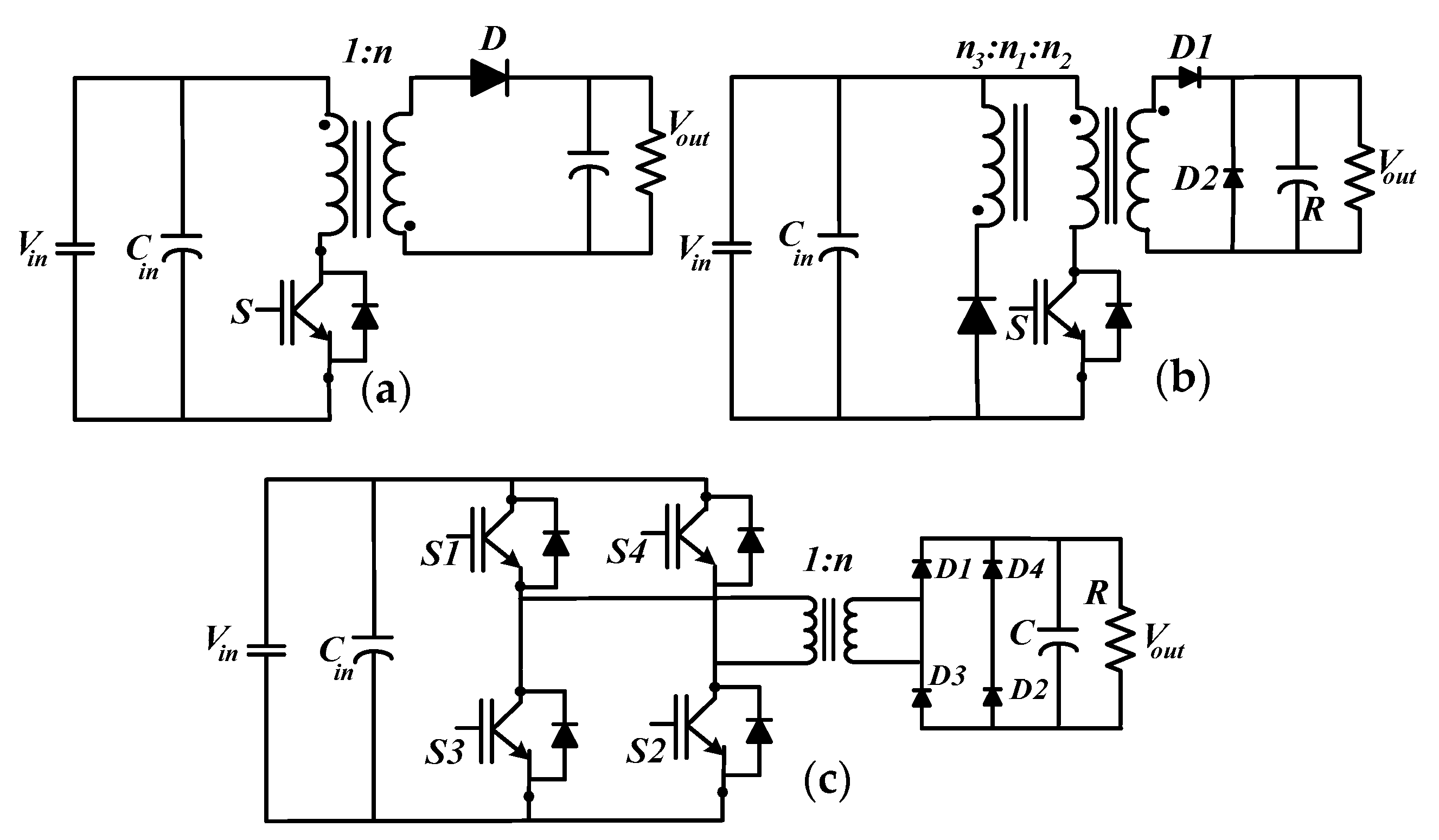
| [39] | Flyback converter | Complex | High | 50 Hz | Resistive | Low | EH |
| [96] | Full-bridge converter | Complex | Low | 30kHz | Resistive | 87–88% | EMEH |
| Product (Company) | Description/Functionality | Shape |
|---|---|---|
| Power Line Sensor (Protura) [143] | - Sends information using general packet radio service. - Driven by a two-piece, specially built transformer that controls from the magnetic field along the transmission line scavenges. - Powered by a harvesting circuit when the line current is more than 55 A. The auxiliary supply power donut (USi) powers the device when the current is lower than the provided value [144]. - Transmits data on demand | 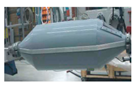 |
| Power Donut (USi) [145] | - Transfers on-demand data through a global mobile communications wireless cell phone technology framework. - Operates using harvested energy given line currents of above 50 A. | 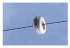 |
| Polydimethylsiloxane (PDMS) [146] | PDMS are largely utilized electronegativity polymer films in the triboelectric nano-generator. The PDMS dimension is 50 mm × 50 mm and is designed as a support case for soft PDMS springs. | 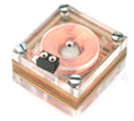 |
| References | Description/Functionality | Figures |
|---|---|---|
| [147] | Several magnetic field designs for harvesting techniques have been proposed in previous studies. The power line sensor (Protura) is an available item that extracts energy from electromagnetic fields. | 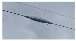 Power line sensor (Protura). |
| [70] | It is a hybrid power-producing method for sensors. In this system, a number of coil-grappled magnets joined to a cantilever are utilized to produce power from an electromagnetic generator. With the system, around 25.45 mW can be obtained with a frequency of 60 Hz. | 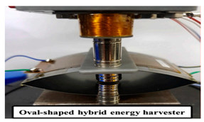 Electromagnetic hybrid energy harvester. |
| [148] | This model generates a power of 58 µW combined with a resistive load of 15 kΩ. In the form of electrical power with a resonant frequency of 50 Hz, an acceleration of 0.59 m/s2, and a power density of 307 μW/m3, the generator may deliver 30% of the total input power to the load. The prototype geometry was set with an applied volume of 0.15 cm3 and a component volume of 0.1 cm3. |  Micro generator cantilever with magnet scale. |
| [149] | It is an electromagnetic piezoelectric hybrid harvester’s power dynamic device. On the basis of the elementary mathematical model, the proposed model was designed and exhibited with the simulation. The initial results show that 46.2 μW and 3.6 μW output powers can be obtained by the portable system from electromagnetic and piezoelectric transducers, respectively, with an excitation frequency of 5 Hz. | 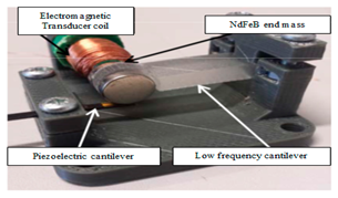 Prototype of a hybrid harvester. |
| [150] | A similar axial–flux permanent magnets generator with eight poles with a diameter of 5 mm. The coil was fabricated differently, given the four layers of copper wound around the stator. NdFeB magnets were utilized in the rotor. These fabrications resulted in a total coil resistance of 30 Ω. When the rotor was rotated using a spindle, given an air gap of 1 mm, the generator delivered a maximum power of 0.412 mW at 2.2 krpm. The authors also indicated the device later generated stator coils using low temperature co-fired ceramic materials. With the use of this technique and with the modification of the test setup, the output power levels reached 1.89 mW at 13,325 rpm. |  Stator with filament windings shown in one layer. |
| [151] | A generator with four magnets, with a volume length of 1.1 cm, a width of 0.9 cm, and a height 0.85 cm. The outcome of this generator is 1 V from an input range of 150 mV at resonance frequency 106 Hz with an acceleration level of 2.6 m/s2. The generator attached with a car engine and from the system produces a peak power of 3.9 mW, which can be obtained with a peak power of 157 µW. |  Electromagnetic generator powered by vibration. |
| [152] | An electromagnetic generator (EG) with discrete coil fabricated with silicon materials. The dimensions of the EG are 525-µm-thick silicon wafer and 25-µm-thick copper wire. The EG produces 0.38V with a frequency of 6.4 kHz. |  Diagram of silicon electromagnetic generator with discrete coil. |
| [153] | This structure contains three spring-mass systems and the proof masses are patterned with double-layer spiral-shaped aluminum coils with dimensions of 10 μm in width and 1 μm in depth. On the other hand, the dimensions of the MEMS EMEH chip, 3 mm in diameter, and 2 mm in height, are mounted through a supporting beam on top of the harvester array. The downside to such a scheme is, it is complicated and costly. Therefore, proper selection of materials at low cost is the best solution to overcome this problem. | 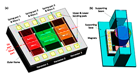 Working principle illustration of electromagnetic MEMS energy harvester (a); setup of electromagnetic MEMS energy harvester (b). |
| [154,155] | It is a meso scale vibration-based EMEH devices with double-layer spring FR4 materials. The basic principle of this vibration transducer is one side fixed and another side open free to move and generate electrical charge via pressure. Therefore, the advantage of such devices is that they can run low-power sensors that are currently powered by the battery; such devices are suitable for the IoT applications. |  (a) Measurement setup of MEMS electromagnetic vibration energy harvester, (b) Meso-scale prototype of Electromagnetic vibration energy harvester. |
| [156,157] | It is a nonlinear vibration-based EMEH structure. The model consists of a combination of Polyethylene terephthalate film, magnets, copper coils, and aluminum shells. The advantage of this model is the upper and lower copper coils are connected in series to gain a maximum voltage outcome. The restriction of this model was the production of a cost-effective combination of composite materials. | 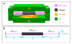 Schematic of the double-clamped beam electromagnetic vibration energy harvester. |
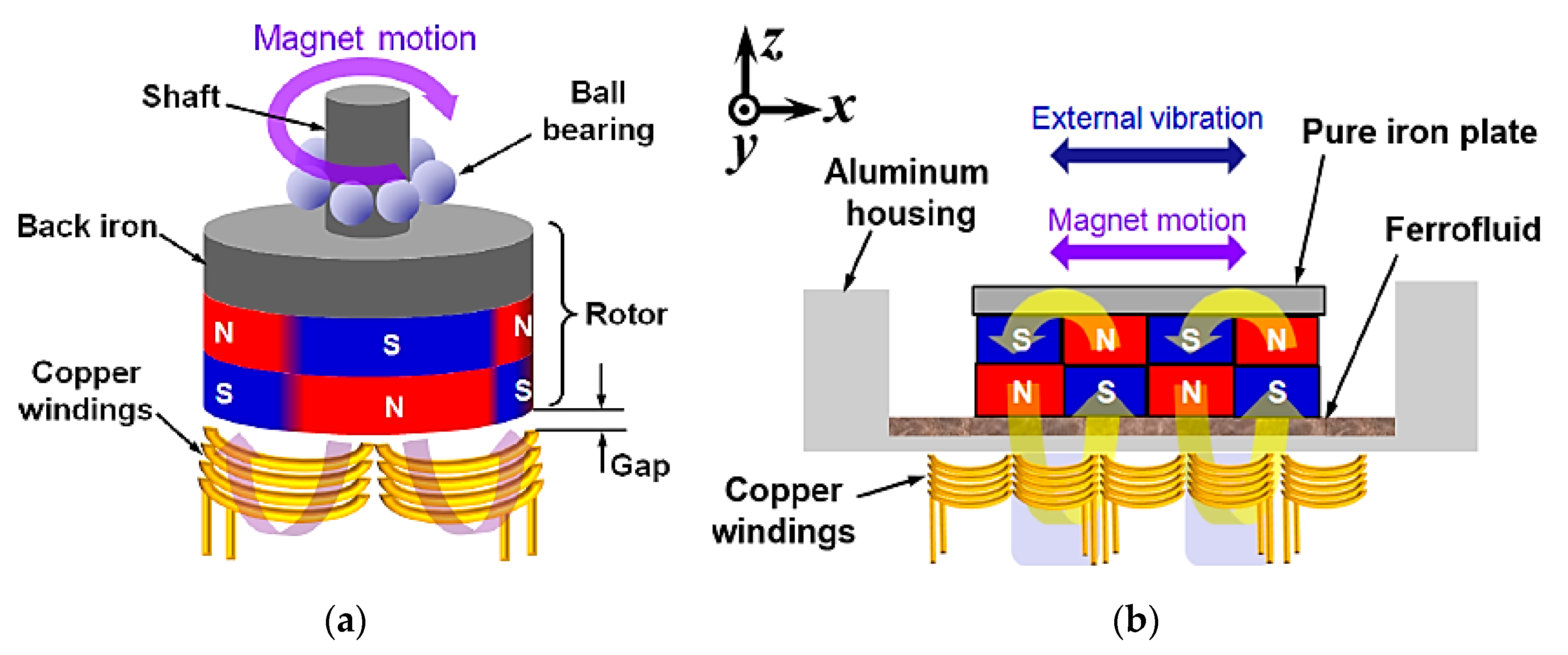
| [41] | It is an EMEH device, which consists of aluminum, pure iron, and copper winding in the top side, and coil bobbins, copper windings, and aluminum in the bottom side respectively. The dimension of this model is 3.7 mm copper winding pitch, which matches the width of the magnet. The minimum distance between the magnet array and the coil is 0.2 mm, which is the aluminum housing’s minimum thickness. The schematic diagram and fabrication of the electromagnetic energy harvester. The dimension of each magnet after fabrication is 3.18 × 12.7 × 1.59 mm3 and 12.7 × 12.7 × 0.2 mm3. The restriction of this model manufacturing process, however, is time consuming with low output power generation. Therefore, the optimal materials and the required dimensions of the systems can be fine-tuned to overcome this problem optimization technique. | 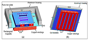 Electromagnetic energy harvester fabrication of the (unit: mm): (a) top side; (b) bottom. |
Publisher’s Note: MDPI stays neutral with regard to jurisdictional claims in published maps and institutional affiliations. |
© 2021 by the authors. Licensee MDPI, Basel, Switzerland. This article is an open access article distributed under the terms and conditions of the Creative Commons Attribution (CC BY) license (https://creativecommons.org/licenses/by/4.0/).
Share and Cite
Sarker, M.R.; Saad, M.H.M.; Olazagoitia, J.L.; Vinolas, J. Review of Power Converter Impact of Electromagnetic Energy Harvesting Circuits and Devices for Autonomous Sensor Applications. Electronics 2021, 10, 1108. https://doi.org/10.3390/electronics10091108
Sarker MR, Saad MHM, Olazagoitia JL, Vinolas J. Review of Power Converter Impact of Electromagnetic Energy Harvesting Circuits and Devices for Autonomous Sensor Applications. Electronics. 2021; 10(9):1108. https://doi.org/10.3390/electronics10091108
Chicago/Turabian StyleSarker, Mahidur R., Mohamad Hanif Md Saad, José Luis Olazagoitia, and Jordi Vinolas. 2021. "Review of Power Converter Impact of Electromagnetic Energy Harvesting Circuits and Devices for Autonomous Sensor Applications" Electronics 10, no. 9: 1108. https://doi.org/10.3390/electronics10091108
APA StyleSarker, M. R., Saad, M. H. M., Olazagoitia, J. L., & Vinolas, J. (2021). Review of Power Converter Impact of Electromagnetic Energy Harvesting Circuits and Devices for Autonomous Sensor Applications. Electronics, 10(9), 1108. https://doi.org/10.3390/electronics10091108