Article

Power Quality Enhancement in Electric Arc Furnace Using Matrix Converter and Static VAR Compensator

1
Department of Electronics and Instrumentation Engineering, RMK Engineering College, Gummidipoondi, Kavaraipettai 601206, India
2
Department of Computer Science Engineering, RMK Engineering College, Gummidipoondi, Kavaraipettai 601206, India
3
Department of Electrical and Electronics Engineering, Sri Venkateswara College of Engineering, Sriperumbudur, Chennai 602117, India
4
Department of Electrical Engineering, College of Electronics and Information Engineering, Sejong University, 209 Neungdong-ro, Gwangjin-gu, Seoul 05006, Korea
5
Department of Energy System Engineering, Chung-Ang University, 84 Heukseok-ro, Dongjak-gu, Seoul 156-756, Korea
6
Department of Mechanical Engineering, College of Engineering, Taif University, P.O. Box 11099, Taif 21944, Saudi Arabia
7
Mechanical Engineering Department, King Abdulaziz University, P.O. Box 80204, Jeddah 21589, Saudi Arabia
*
Authors to whom correspondence should be addressed.
Electronics 2021, 10(9), 1125; https://doi.org/10.3390/electronics10091125
Submission received: 3 April 2021 / Revised: 1 May 2021 / Accepted: 7 May 2021 / Published: 10 May 2021
(This article belongs to the Section Power Electronics)

Abstract

:
In recent years, non-linear loads on the distribution side are increasing rapidly. Notably, the electric arc furnace (EAF) is the most used non-linear load due to its diverse applications for industrial needs. However, EAF has some disadvantages like uneven distribution of heat inside the furnace, release of unwanted gases, increased level of harmonics, and Flickers in voltages. Specifically, power quality concerns are more and need comprehensive solutions. In this work, a matrix converter (MC) along with static VAR compensator (SVC) is proposed, and the hybrid exponential-hyperbolic furnace model is adapted in MATLAB platform. Simulations are carried out for different cases and the observed results are compared with existing methodologies. It was perceived that the power quality parameters such as peak current and voltages, total harmonic distortions (THDs), voltage flickers, and power factors are enhanced compared with existing methodologies. Precisely, the THD of current and voltage attains a prime rate of about 2.85% and 29.54%, respectively. Moreover, the proposed model’s voltage flicker and power factor offer a grander scale of about 1.26% and 0.9975, respectively. The enhanced scheme provides more significant advantages to the large-scale steel manufacturing plant with EAF.

1. Introduction

Nowadays, the usage of steel in the modern world is increasing rapidly due to the higher demand rate. It is used in various fields such as construction, infrastructure, transportation, medical, and weapons. Notably, around 52% of the steel is used for building and infrastructure purposes, and the remaining in other sectors like domestic appliances, mechanical equipment, electrical appliances, etc. The steel production was around 189 million tons in the 1950s, and it increased to 1869 million tons in 2019. Among the countries, China produces approximately 1000 million tonnages of steel every year and stands first in steel production. Secondly, India has around 120 million tonnages every year [1]. The increasing usage of steel is achieved only by the mass production of crude steel. The electric arc furnace (EAF) is the primary industrial device used in many industries for steel production. It works in several megavolts with kilo ampere electrical loads. Extensive research is happening in the field of EAF in recent times. As it consumes more electric energy, a slight increase of efficiency can offer a superior scale of power savings [2].
EAFs are mainly used for melting and dissolving the iron; used for steel production. Since it consumes a higher magnitude of power, the problems related to power quality like harmonics, flickers, and voltage fluctuations also increase exceedingly due to the non-linear voltage-current characteristics (VIC) of EAF. The magnitude of voltage fluctuation is based on the length of the electric arc. These shortcomings result in the improper working of the devices, rapid aging, and reduced efficiency in transmitting and receiving sides [3]. EAF causes power quality issues due to its non-linear characteristics. The distortion in the furnaces arises mainly due to flickers (due to sub-cycle distortions), harmonics (due to intra-cycle distortion), and interferences (due to high-frequency distortion). These three categories can play a vital role in deciding the performance and quality of the EAFs [4]. The other issues that may arise in EAFs are the voltage sag and swell, interruptions, transients, voltage unbalance, and fluctuations. Moreover, it is essential to reduce the power loss, reduction in electricity consumption, maximum voltage input, and capacity improvement [5]. This work concentrates on the overall performance enhancement of the EAF. The literature survey is performed and described as follows based on these needs.
Several works demonstrate the performance of the EAF with enhanced power quality parameters. Notably, Jose Rodriguez et al. [6] summarized the control and modulation methods of Matrix converters (MC). Various matrix converters and control algorithms were presented with numerous controls and modulation methods [7]. The author concluded that the predictive current and torque control provided more advantages when compared to other conventional methods, namely Venturini, scalar, and carrier-based PWM and SVM [8]. Further, Naveed Ashraf et al. [9] introduced a new single-phase buck book MC with minimized switching stresses. This converter assisted in rectifying the voltage swell and sag in the power systems.
Additionally, a bipolar gain was used for direct ac to ac conversion, and the proposed converter could be used as a voltage and frequency controller. Moreover, Srividhya et al. [10] suggested a fuzzy logic-based indirect MC with vector controller and fuzzy logic controller that offered a better result in the voltage sag conditions [11,12]. Additionally, Tabish nazir Mir et al. [13] demonstrated the usage of MC that improved the power quality in the source and load side. The reference and the adaptive model outputs were analyzed, and the error values given to the PI controller. The controller changed the inputs to the adaptive model until the error becomes zero, and the advantages of using MC in the non-linear load were presented with simulation results.
Moreover, Yao Sun et al. [14] dealt with the addition of diodes in MC used in the high-power area. This new converter provided extra advantages: eliminating voltage imbalance and the distinct advantages like neatly packed structure, simple commutation techniques, bidirectional power flow, and sinusoidal input and outputs. Further, the low switching loss and better reliability could be achieved by this diode-clamped MC. Additionally, D Casadei et al. [15] addressed the instability phenomenon of the power systems, and the instability was reduced using the DSP controller as feedback in the MC. The voltage and current values in the input and output sides calculated using the processor, and the DSP controller controlled the PWM control strategy.
Additionally, Gary W. Chang et al. [16] evaluated the effect of neural network-based electric arc furnaces. This method was used to access the waveform distortions, variations in the voltage, and the reactive power components’ performance. The simulation output was compared with the existing systems, and it offered better results, and this method can be used in any non-linear load. The RBFNN and LUT method were employed for studying the dynamic characteristics and modeling of voltage and current waveforms. Moreover, M. Barbouche et al. [17] concentrated on silicon carbide (SiC) growth using a small EAF. SiC and MG-Si were mainly used in many electronic applications and solar power generation applications. This work used Raman spectroscopy to analyze the SiC and the entire mechanical parts were produced, assembled, and tested using LabVIEW NI environment.
Likewise, the artificial neural network was adopted to model EAFs [2] and arc-length computation. Specifically, this system found the arc length in stable and unstable conditions. The furnace efficiency and productivity were improved using the ANN-based electric arc furnace. Further, Rahmatollah Hooshmand et al. [18] discussed a new time-domain model for EAF. The performance of EAF was analyzed using three models, namely hyperbolic model, complete exponential model, and the proposed exponential-hyperbolic model. The proposed exponential, hyperbolic model offered an excellent approximation without initial conditions of EAF. The voltage-current characteristics and total harmonic distortion (THD) were derived with good approximation. Moreover, Philippe Ladoux et al. [19] performed a comparison between ac and dc converters for the electric arc furnace. A new control strategy was used based on diode rectifiers and choppers to suppress the effect of flickers and increase efficiency.
Furthermore, Yogesh V et al. [20] described the challenges in PID controller design. A complete literature review was presented on the controller’s plan and the control algorithms. The issues faced in the past and the current scenario were addressed satisfactorily. The tuning methods were separated accordingly to internal mode, fractional order, soft computing, and robust control schemes. Additionally, Jignesh Kumar Patel et al. [21] provided various digital controllers in any power controller network. There were different types of controllers like traditional analog, advanced hybrid, and technological digital controllers. The control algorithms might vary from a simple to an advanced artificial intelligence-based control. The evolution of DC converters to power electronic converters happened with a mono level switch to multi-level converter topologies.
Further, Wan-Rone Liou et al. [22] adapted a PWM array, with analog to digital controllers (input), digital to analog converters (output), and a processor control unit for power controller circuits. An advanced hybrid control algorithm was adapted to attain a unity power factor. A higher efficient power conversion was achieved by this method. The acquired power factor was very close to unity, and the ripple voltage performance was close to 100%. In addition, Ricardo Lucio et al. [23] introduced an active control algorithm for the non-linear and changing load. This filter-based control algorithm was used in an electric arc furnace as the load is non-linear and dynamic [24]. The output was used as a reference and fed into the input circuit for power factor corrections.
Moreover, Yu-Wei Liu et al. [25] demonstrated static VAR compensator (SVC) application and active filter for power quality improvement connecting the EAF. Simulation study confirmed the enhancement notably power factor and balance load current. Further, fuzzy logic control was adapted for the optimal design of SVC to enhance the voltage profile of the system connecting the EAF [26]. The compensating device rapidly controlled the system parameters that enhance the voltage profile of the system and reduced harmonic currents. Moreover, a novel topology was developed by Ebrahim Babaei et al. [27] based on the application of dynamic voltage restorer (DVR) and direct converters. This scheme verified its capability for compensation of voltage distortions.
Also, Ahsan Habib et al. demonstrated the effectiveness of DVR to alleviate the power quality disturbances using a phase-locked loop, proportional integral, and supercapacitors. The proposed scheme offered a better efficacy in power quality [28]. Moreover, the synchronous detection method and digital control based on instantaneous power theory were demonstrated for the control active power filter. The digital management offered better power quality than the synchronous detection method [29].
Consolidating all the reports, a unique EAF model with advanced control technology is required to enhance the system power quality, namely, integrated innovative power converters with compensating devices. From the literature surveys, it is found that the application of matrix converter (MC) along with static VAR compensator (SVC) was not demonstrated for electric arc furnace to enhance the power quality. Notably, MC is attracting more attention recently due to its exciting features, namely compact design, bidirectional power flow, controllable input reactive power, and sinusoidal input/output currents [30]. In addition, they have stretched a good height of technological maturity that permits their practical and industrial application in a variety of domains, notably industrial drives, power supplies, and aerospace applications [31]. Based on the limitations from surveys and advantages of MC, this work focuses on the following objects:
  • To design the cutting-edge electric furnace model for a virtual demonstration.
  • To adopt the advanced power converters for EAF.
  • To integrate the compensating devices along with advanced power converters.
  • To improve the overall performance of the power supply, such as arc voltage, arc current, THDI (Current THD), THDV (Voltage THD), power factor, and voltage flicker.
Considering the above objectives, this article organized as follows: Section 2 demonstrates the proposed methodology comprised of various components. Section 3 describes the detailed results and discussion based on the observed outcomes from the simulation. Subsequently, a comparative analysis between various models is performed in Section 4. Finally, conclusions are made based on the observed results in Section 5.

2. Proposed Methodologies

This section illustrates the proposed scheme comprised of Source, HV/MV transformer, SVC, furnace transformer, Matrix converter along with DSP based controller and the electric furnace as demonstrated in Figure 1. The design parameters of the SVC comprises of 415 V, 8 MVA rated capacity with 22.5 mH of reactor bank paralleled with 223.6 μ F of capacitor bank. The impedances of source and furnace transformers are considered as 0.052 + j0.46 and 0.336 + j3.23 respectively with system frequency of 50 Hz. Moreover, the input fuction of the EAF is descried using the following syntax:
  • function v = fcn(f,i)
  • C = 23,000;
  • D = 5000;
  • m = 0.8;
  • Vat0 = 200;
  • vt = Vat0 × (1 + (m × f));
  • v = sign(i) × (vt + (C/(D + abs(i))));
A detailed description of various elements of the proposed scheme is discussed below.

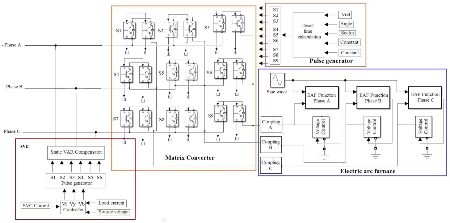
2.1. Matrix Converter (MC)

The proposed scheme uses a matrix converter and an input filter that supplies power to the electric furnace, as illustrated in Figure 2. The output voltage and current of the MC to input voltage and current are derived as follows [30,31,32,33]:
V 0 = V a V b V c = S A a S B a S C a S A b S B b S C b S A c S B c S C c   ×   V A V B V C = S × V i
I i = I A I B I C = S A a S A b S A c S B a S B b S B c S C a S C b S C c   ×   I a I b I c = S T × I 0
where ST denotes a transpose of matrix S, and states of each bidirectional switches are represented as Sxy (x indicates A, B, and C and y denote a state a, b, and c) that can be derived as follows:
S x y = 0               i f             S x y           i s           o p e n 1               i f             S x y           i s           c l o s e
MC uses the space vector modulation (SVM) control algorithm that represents the three-phase current and voltage on the vector plane. Each output phase is given as an input to the stage considering the states of switches. A total of twenty-seven switching states are admissible to evade the short and open circuit in the incoming side using the above functions. Among the combinations, three groups are formed based on the output phases relating to the respective input phases. The output of the MC is based on the SVM parameters such as instantaneous voltage and current, and phase angles of the input ( i ) and output voltages ( 0 ). Moreover, a duty period for each switching operation is computed to attain the desired output voltage and frequency referring at the MC. The below equations represent a switching time concerning two-phase angles.
δ 1 + = 2 3 T s q sin α 0 + π 6 sin π 3 α i δ 3 = 2 3 T s q sin α 0 + π 6 sin α i δ 4 = 2 3 T s q sin π 6 α 0 sin π 3 α i δ 6 + = 2 3 T s q sin π 6 α 0 sin α i
where δ 1 + + δ 3 + δ 4 + δ 6 +     T s Further, the MC input current and the output voltage are estimated using the below equations.
V 0 = 2 3   V a + a . V b + a 2 . V c = V 0   m a x . e j 0
I i = 2 3   I A + a . I B + a 2 . I C = I i   m a x . e j β i
where ‘a’ is an operator that can be represented as e j 2 π 3 . Then the terms V x   a n d   I x   x = a , b , c are the output voltages and input currents of the MC respectively. Moreover, the term V 0   m a x and I i   m a x are the scale of output voltage and input current, respectively, and the term 0 and β i are the angles (voltage and current respectively). Further, various switching operations states and the respective output voltage and the input current are illustrated in Table 1 derived using a DSP based controller.
Further, the input filter circuit is designed using a capacitor (Cf), inductor (Lf), and resistor (Rs), and the equivalent single-phase model is illustrated in Figure 3.
From the above figure, the input current Is(s) is expressed as the function of the input voltage (Vs) and MC input current (IMC). Further, the frequency response of the output voltage and current of the filter (i.e., input voltage and current to MC) is expressed as follows:
I i s = 1 R f C f + 1 L f C f s 2 + s R f L f + 1 L f C f   I M C s           V i s = 0
V c f s = R f s 1 L f C f s 2 + s R f L f + 1 L f C f   I M C s           V i s = 0
The canonical representation of the above equations are expressed as follows:
a s = ω n 2 s 2 + 2 ξ ω n s + ω n 2 b s
c s = s ω n α ξ + ω n 2 s 2 + 2 ξ ω n s + ω n 2 b s
ω n = 1 L f C f   , ξ = R f 2 C f L f   , Q = 1 R f L f C f
where ω n , ξ and Q denotes the natural frequency, damping factor, and quality factor, respectively.

2.2. Furnace Transformer
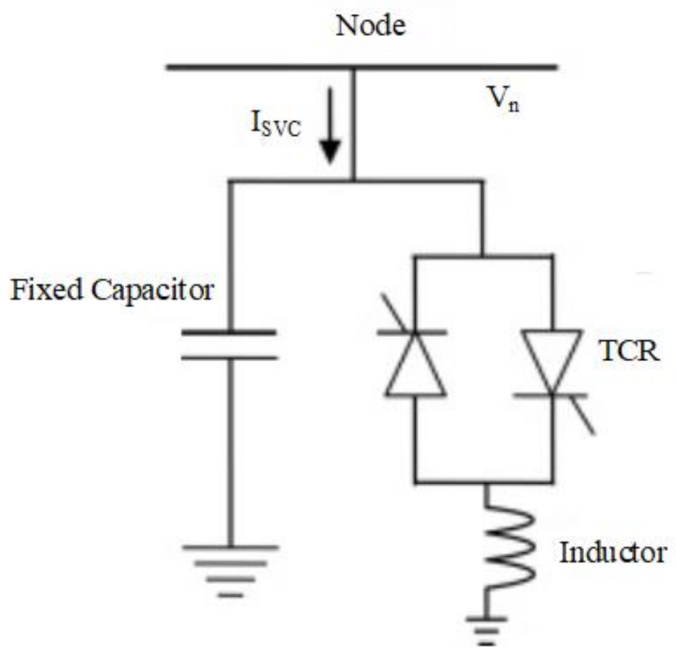
The furnace transformer involves a unique design, and its circuit equation can be derived as follows:
E t r = 3 Z 1 I e + U 1
where Z 1 defines the impedance of the furnace transformer that can be formulated using Equation (13). Further, the term I e and U 1 denote the electrode current and source voltage, respectively.
Z 1 = R 1 2 I 2 . T + X 1 2 T
where R1 and X1 are the resistance and reactance of the transformer, and they can be represented as below:
R 1 = P E F P a r c 3 I e 2
X 1 = 1 3 I e U 1 2 P E F P a r c 2 3 I e 2
where P E F and P a r c are the furnace and arc power, respectively.

2.3. SVC

To obtain steady-state power for EAF and improvement of voltage profile, SVC is adapted that can inject or absorb the reactive power based on the incoming circuit nature [34,35]. It consists of a fixed capacitor, inductor and thyristor controlled rectifier, as illustrated in Figure 4. The total reactive power injection or absorption of the device can be expressed as follows [30,31]:
Q S V C = B × V 2
where ‘B’ denotes a susceptance offered by the SVC that can control the reactive power (positive value terms the injection and negative scale represent the absorption) and V represents the voltage. The range of the susceptance can be formulated as follows:
B m a x = 1 S b Q c a p + X T p u
B m i n = 1 S b Q i n d X T p u
where S b represent the base power in MVA, X T p u is the transformer reactance in per unit, Q c a p and Q i n d are the reactive capacitance and reactive inductive, respectively, and B m a x and B m i n are the maximum and minimum reactive power of the capacitor and inductor, respectively. The total capacitance required for the design is calculated using the following equation.
C = B c a p 2 π f
The following condition needs to satisfy for adequate compensation:
Q S V C = Q l o a d Q u n c o m p e n s a t e d
B c a p = Q l o a d Q u n c o m p e n s a t e d V r m s 2
Q S V C ,   m i n < Q S V C < Q S V C ,   m a x

2.4. Electric Arc Furnace (EAF)

The modeling of EAF is performed based on the V-I Characteristics (VIC), which comprises a solution of a non-linear differential equation that meticulously approximates the actual arc furnace. The accurate and linearized model VIC is compared to justify the precision between them as represented in Figure 5. The vital parameters such as ignition and extinction voltage are considered to determine the arc length during the operation. Various time-domain models can be derived by approximating the actual VIC and described in the following sub-sections.

2.4.1. Approximation Model

Based on the characteristic plot of V-I (voltage-current), a linear piecewise model EAF is derived. With the arc length during arc furnace operation, the ignition voltage ( V i g ) and extinction voltage of arc ( V e x ) are determined. The actual furnace model is derived in a virtual platform using two linear equations. Therefore, the complete on cycle model is considered, and the relation between voltages of arc and current of arc is described as follows:
V o l t a g e = S 1 i i f i i i 1 S 2 i + V i g ( 1 S 2 / / S 1 ) i f i < i i 2 S 2 i V i g ( 1 S 2 / S 1 ) i f i 2 i < i 1
where
i 1 = V i g S 1
i 2 = V e x S 2 V i g 1 S 2 1 S 1
where ‘S1 ‘and ‘S2‘ represent a linear slope achieved from VIC approximation between the limits −i1 and, i1 and i2 respectively; i1 and i2 are the arc current attained at the ignition extinction voltage of the arc, respectively.

2.4.2. Piecewise Model

The accurate piecewise non-linear model can be developed by assuming a portion of V-I characteristics. The processes of melting of arc are divided into different sections. Initially, the magnitude of the voltage rises to ignition voltage v i g from extinction voltage v e x . Then, the resistor acts as a furnace arc, and the polarity of current varies from i3 to i1. Secondly, the dissolving process gets started. Henceforth, an unexpected voltage drop of exponential through the electrode has occurred, and therefore voltage of the arc is reduced to v s t from v i g . Moreover, the current of the arc rises lightly from i1 to i2. Finally, a general dissolving procedure has taken place, i.e., the voltage of the arc linearly falls smoothly and slows down from v s t to v e x , as described in Equation (26).
V o l t a g e = S 1 i ( i 3 i i 1 . i n c ) ( i 1 i i 3 , d e c ) V s t + ( V i g V s t ) exp ( ( i i 1 ) / i T ) i 1 i i 2 , i n c V s t + i i 2 S 2 i i 2 , i n c V e x + ( i i 3 ) S 3 i i 3 , d e c V s t + ( V s t V i g ) exp ( ( i + i 1 ) / i T ) i 2 i i 1 V s t + ( i + i 2 ) S 2 i < i 2 , d e c V e x + ( i + i 3 ) S 3 i < i 3 , i n c
where S 1 , S 2 , and S 3 are the equivalent slopes of each section.
i 1 = v i g S 1 i T = 1.5 i 1 i 2 = 3 i 1 i 3 = v e x S 1

2.4.3. Hybrid Model (Exponential-Hyperbolic)

The exponential furnace model is derived from V-I characteristics, and it can be derived as follows:
V e = V a t × 1 e i I 0            
where V e denotes the arc voltage derived from the exponential model; V a t represent the threshold voltage; i defines the arc current per phase; and I 0 denotes a current constant that represents the positive and negative steepness of the model.
The hyperbolic furnace model derived from the same VIC using the following equation.
V h = V a t + C D + i
where V h denotes the arc voltage obtained from the hyperbolic model; the variables C and D represent the arc power and current.
Then the hybrid model ( V h y b ) is developed by combining both models, i.e., exponential and hyperbolic. It can be formulated using the below equation.
V h y b = V a t + C D + i                   f o r   l o w   c u r e n t V a t × 1 e i I 0       f o r   h i g h   c u r e n t      
where V a t = A + B . l ; A and B are the measurements from the experimental formula; and l represent the arc length in centimeters. Further, the sinusoidal flicker in the power system is derived using the below equation.
V a t = V a t 0 1 + m . sin ω f . t
where m and ω f denotes a modulation index and flicker frequency, respectively.
It is a known fact that the flicker measurement is based on the RMS voltage of the system and its respective frequency. The percentage measurement of flicker is computed using the equation below.
% V o l t a g e   f l i c k e r = R M S   V o l t a g e   o f   m o d u l a t i n g   w a v e f o r m   R V M W A v e r a g e   R M S   v o l t a g e   A R V
R V M W = V 2 = V 2 p V 1 p 2 2   and   A R V = V 2 p 2 2 + V 1 p 2 2 = V 2 p + V 1 p 2 2
where V 2 p and V 1 p represent the upper and lower peak voltage, respectively. After substituting the above equations, the percentage of voltage flicker is derived as follows:
% V o l t a g e   f l i c k e r = V 2 p + V 1 p V 2 p V 1 p

3. Results and Discussions

The comprehensive model is designed in MATLAB Simulink software, and the simulations are done for different cases. The input voltage and current, and the corresponding output are studied for the three models. It consists of a three-phase input source shifted by the angle 120° apart. The voltage-controlled source is adapted as a non-linear time-varying case that represents the furnace model. The complete description of the model developed in Simulink is illustrated in Figure 6. The output of the system is a non-linear time-varying voltage that can be generated due to the input given as arc current. The model’s vital parameters can be extracted, such as three-phase voltage and current and THD for two cases, namely with and without SVC. In addition, flicker measurements are carried out using Figure 7 that can be implemented in the SIMULINK.
The proposed system is simulated to demonstrate the power quality of the supply by illustrating the voltage and current harmonics, power factor, and voltage flicker. The complete description of the observed results is discussed in the following subsections.

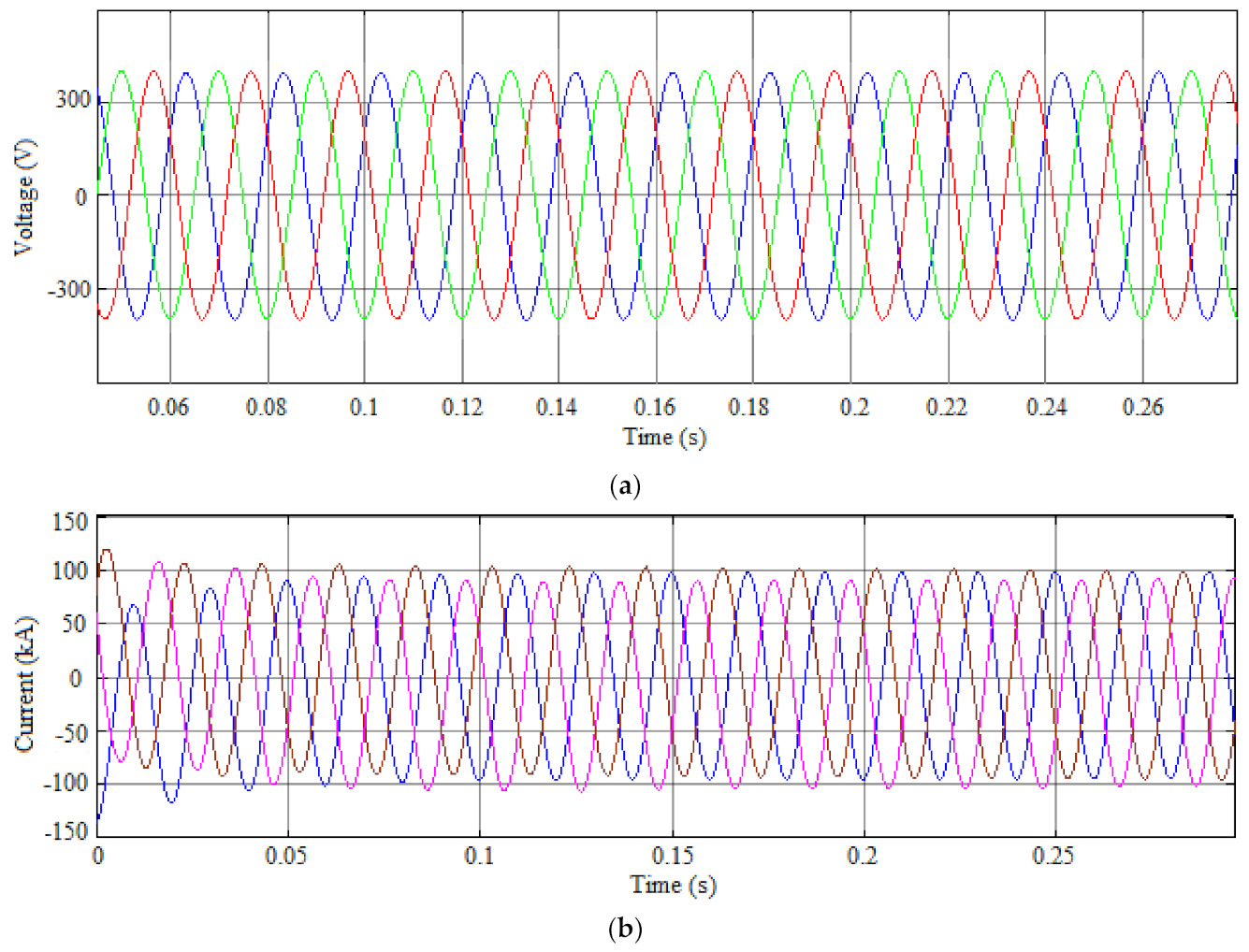
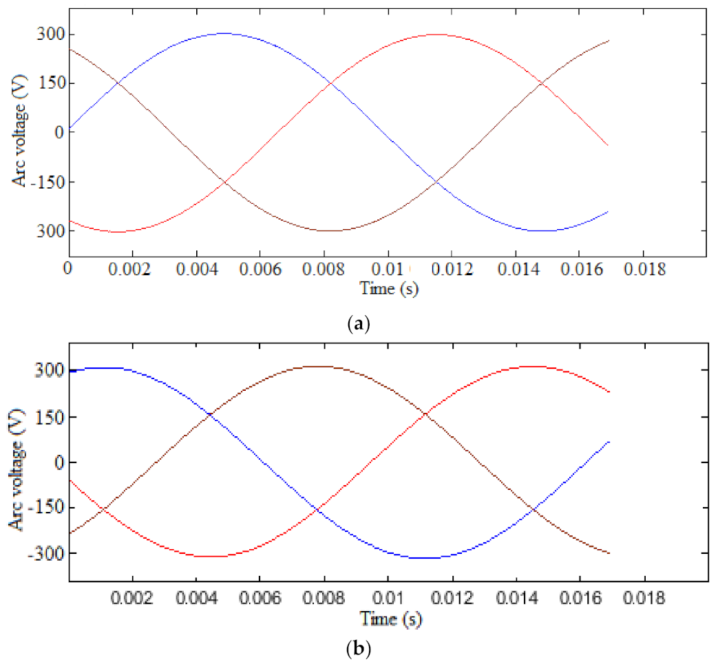
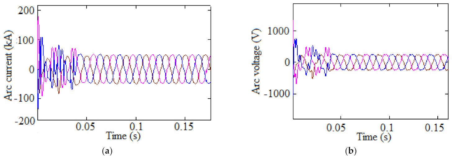
3.1. Current and Voltage Waveforms

As stated earlier, the application of MC is simulated for two conditions, namely with and without SVC integration into the developed model. The input voltage and current for the matrix converter are derived from the filter circuit, as illustrated in Figure 8a,b respectively. It is observed that the waveforms exhibit a controlled three-phase input that can be given to the MC to meet the demand of the non-linear load (EAF). This is due to adapting compensating devices that maintain a controlled input to the converting segment.
Further, the waveforms of arc currents are illustrated in Figure 9 for both cases. It is observed that there is a trivial variation of current magnitude between the hybrid model with MC and a hybrid model with MC and SVC, i.e., 121.59 kA, and 123.26 kA, respectively. The wave shapes of both cases are nearly similar, with a slight variation in the angle.
Similarly, the waveform for arc voltages is computed and illustrated in Figure 10. It is observed that there is a variation in the voltage magnitude between the two cases as described in the arc current. The voltage magnitudes are logged as 308 V and 314 V, i.e., with MC and MC-SVC. It is observed that the proposed system injects the required voltage to the source that could stabilize the arc voltages commendably.

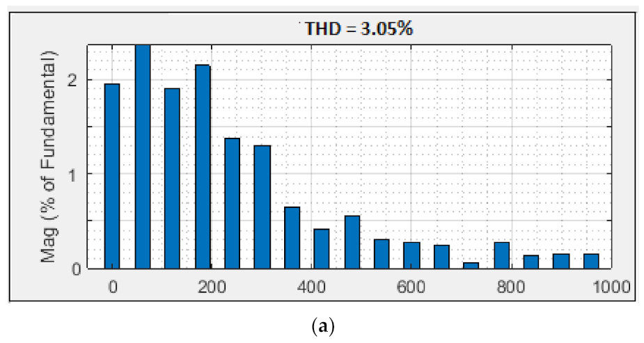
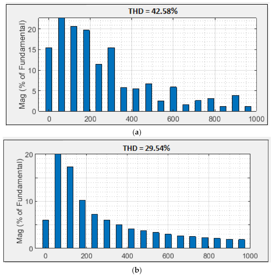
3.2. Harmonic Analysis
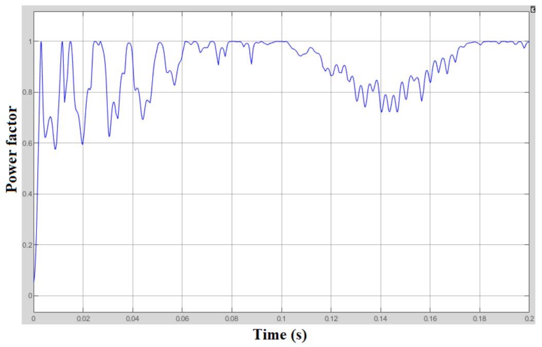
The analysis of current harmonics is carried out for both cases and the respective THDs are illustrated in Figure 11. It is observed that the hybrid model with MC shows the least THD of about 3.16%. In addition, the THD of the hybrid model with MC and SVC condense the rate further reached about 2.85%, which is the smallest compared with the hybrid model with MC. This is due to the enhancement of power quality parameters with SVC integration.
Subsequently, the voltage harmonics are evaluated, and the respective characteristics are illustrated in Figure 12. From the analysis, it is perceived that the THD of the SVC model logged a better range of about 29.54%, which is exceptionally great compared with the MC model (42.58%).
It is noted that the proposed compensating scheme enhances not only the power factor of the system but also aids in maintaining the THD level of the system within a band, as described earlier.

3.3. Power Factor

After compensation, the systems power factor is measured with respect to time. SVC injected the reactive power to a great extent to attain a better power factor, as demonstrated in Figure 13. The load current combines with the compensating current of the SVC that affects the closer to unity power factor, i.e., 0.9975. This ensures a superior power quality enhancement for high non-linear loads, notably EAF.

3.4. Voltage Flicker

The magnitude of voltage flicker is computed using dynamic characteristics that represent the melting process of the furnace. This operation exhibits severe voltage flickering, and this can be derived through simulation study based on Equation (34). The evaluation of voltage flicker can be considered as continuous voltage sags and swells. The proposed compensating system, i.e., SVC can compensate voltage sag and swell as well as voltage flicker. The observed results of flickering for voltage waveform and the respective current components for a hybrid model with MC and SVC are illustrated in Figure 14. It is known that there would be severe evidence of flicker during the melting process of the furnace. However, the proposed model logged the most petite range than the hybrid model with MC.

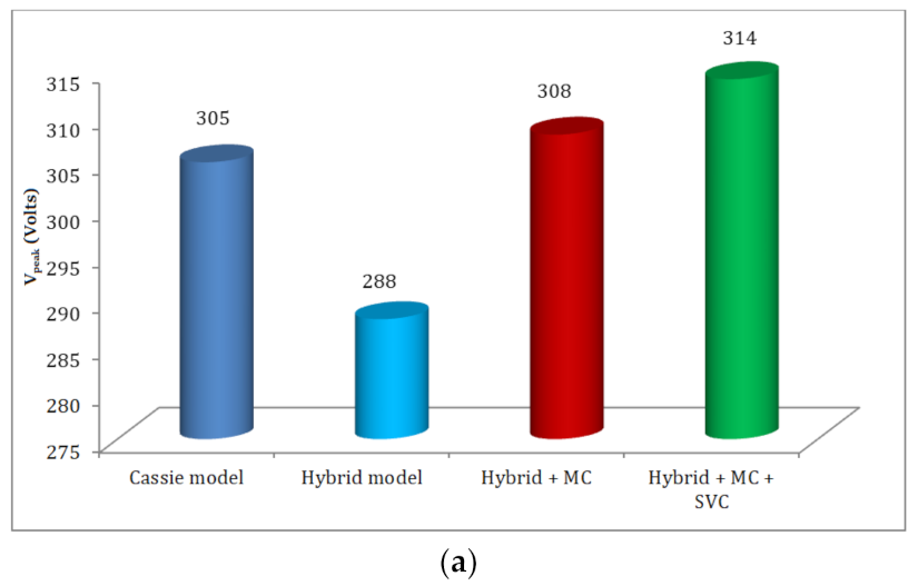
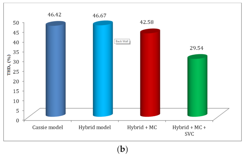
4. Comparative Analysis

The comparative analysis is performed between the proposed and existing model for various power quality parameters such as Ipeak, Vpeak, THDV, THDI, voltage flicker, and power factor. The existing models considered in this study are the Cassie model and the hybrid model (exponential-hyperbolic), and these performances are compared with the hybrid-MC and hybrid-MC-SVC model illustrated in Figure 15, Figure 16 and Figure 17.
From the above figures, it is perceived that the peak voltage and current of the proposed model show a more excellent value of 314 V and 123.26 kA, respectively, which are more significant than other models. Moreover, the current and voltage THD is less for the proposed model (2.8% and 29.54%, respectively), as illustrated in the above figures. Further, the voltage flicker is compared with other existing models, and it shows a minor percentage of 1.26%. Finally, the power factor of the proposed scheme exhibits a higher value of 0.9975, which is greater than the other existing models. The overall performance of the proposed model shows more excellent value due to their combined function of MC and SVC.
Considering all these inferences, it is observed that the proposed model with MC and SVC enhances the quality of the power supply, and this can be applied to the real-time furnace operation for effective characteristics.

5. Conclusions

This work demonstrated an advanced time-domain EAF model with DSP-based MC and SVC. This proposed model enhanced the overall power quality of the system. The following conclusions are made based on the observed results:
  • The proposed model offers superior outcomes compared with existing EAF models.
  • Arc currents and voltages (peak value) show greater magnitudes of about 123.26 kA and 314 V, respectively.
  • The proposed scheme offers the slightest current and voltage THD values of about 2.85% and 29.54%.
  • The voltage flickering of the proposed model shows minimum scale compared with other existing models, i.e., 1.26%.
  • The power factor of the proposed scheme shows a superior rate of about 0.9975.
With these enhanced outcomes, the proposed method can be adapted for real-time application i.e., a steel manufacturing plant that can offer enriched power quality with energy-efficient operation.

Author Contributions

Conceptualization, B.S.J.; Methodology, B.S.J. and J.B.; Software, B.S.J.; Validation, R.K.; Formal Analysis, R.K. and M.H.A. (Mohammed H. Alsharif); Data Curation, B.S.J.; Writing—Original Draft Preparation, B.S.J. and R.K.; Writing—Review & Editing, M.H.A. (Mohammed H. Alsharif) and A.A.A.; Supervision, M.H.A. (Mohamed H. Ahmed); Funding Acquisition, M.-K.K. All authors have read and agreed to the published version of the manuscript.

Funding

This research was supported by the Chung-Ang University Research Grants in 2021. This research was also supported by Basic Science Research Program through the National Research Foundation of Korea (NRF) funded by the Ministry of Education (2020R1A2C1004743). In addition, this research support by the Taif University Researchers Supporting Project number (TURSP-2020/77), Taif University, Taif, Saudi Arabia.

Conflicts of Interest

The authors declare no conflict of interest.

References

  1. World Steel Association. World Steel in Figures. 2020. Available online: https://www.worldsteel.org/en/dam/jcr:f7982217-cfde-4fdc-8ba0-795ed807f513/World%2520Steel%2520in%2520Figures%25202020i.pdf (accessed on 1 May 2021).
  2. Garcia-Segura, R.; Castillo, J.V.; Martell-Chavez, F.; Longoria-Gandara, O.; Aguilar, J.O. Electric Arc Furnace Modeling with Artificial Neural Networks and Arc Length with Variable Voltage Gradient. Energies 2017, 10, 1424. [Google Scholar] [CrossRef]
  3. Teklić, A.T.; Filipović-Grčić, B.; Pavić, I. Modelling of three-phase electric arc furnace for estimation of voltage flicker in power transmission network. Electr. Power Syst. Res. 2017, 146, 218–227. [Google Scholar] [CrossRef]
  4. IEEE 1993. IEEE Recommended Practices and Requirements for Harmonic Control in Electrical Power Systems; IEEE: New York, NY, USA, 1993. [Google Scholar]
  5. Ozgun, O.; Abur, A. Development of an arc furnace model for power quality studies. In Proceedings of the IEEE Power Engineering Society Summer Meeting, Edmonton, AB, Canada, 18–22 July 1999; Volume 1, pp. 507–511. [Google Scholar]
  6. Rodriguez, J.R.; Rivera, M.; Kolar, J.W.; Wheeler, P.W. A Review of Control and Modulation Methods for Matrix Converters. IEEE Trans. Ind. Electron. 2012, 59, 58–70. [Google Scholar] [CrossRef]
  7. Khosravi, M.; Amirbande, M.; Khaburi, D.A.; Rivera, M.; Riveros, J.; Rodriguez, J.; Vahedi, A.; Wheeler, P. Review of model predictive control strategies for matrix converters. IET Power Electron. 2019, 12, 3021–3032. [Google Scholar] [CrossRef]
  8. Zhang, G.; Yang, J.; Sun, Y.; Su, M.; Zhu, Q.; Blaabjerg, F. A Predictive-Control-Based Over-Modulation Method for Conventional Matrix Converters. IEEE Trans. Power Electron. 2017, 33, 3631–3643. [Google Scholar] [CrossRef]
  9. Ashraf, N.; Izhar, T.; Abbas, G. A Single-Phase Buck-Boost Matrix Converter with Low Switching Stresses. Math. Probl. Eng. 2019, 2019, 1–19. [Google Scholar] [CrossRef]
  10. Vidhya, D.S.; Venkatesan, T.; Kanagaraj, N. Fuzzy Logic Controller for Variable Boost Function in Quasi Z Source Indirect Matrix Converter during Voltage Sag Condition. Int. J. Fuzzy Syst. 2016, 19, 1093–1103. [Google Scholar] [CrossRef]
  11. Basri, H.M.; Mekhilef, S. Experimental Evaluation of Model Predictive Current Control for a Modified Three-Level Four-Leg Indirect Matrix Converter. IET Electr. Power Appl. 2017, 12, 114–123. [Google Scholar] [CrossRef]
  12. Garcia, C.F.; Rivera, M.E.; Rodriguez, J.R.; Wheeler, P.W.; Pena, R.S. Predictive Current Control with Instantaneous Reactive Power Minimization for a Four-Leg Indirect Matrix Converter. IEEE Trans. Ind. Electron. 2017, 64, 922–929. [Google Scholar] [CrossRef]
  13. Mir, T.N.; Singh, B.; Bhat, A.H. New Modulation Techniques for Single Phase to Three Phase Matrix Converter. In Proceedings of the 2018 IEEE International Conference on Power Electronics, Drives and Energy Systems (PEDES), Chennai, India, 18–21 December 2018; pp. 1–6. [Google Scholar]
  14. Sun, Y.; Xiong, W.; Su, M.; Li, X.; Dan, H.; Yang, J. Topology and Modulation for a New Multilevel Diode-Clamped Matrix Converter. IEEE Trans. Power Electron. 2014, 29, 6352–6360. [Google Scholar] [CrossRef]
  15. Casadei, D.; Clare, J.; Empringham, L.; Serra, G.; Tani, A.; Trentin, A.; Wheeler, P.; Zarri, L. Large-Signal Model for the Stability Analysis of Matrix Converters. IEEE Trans. Ind. Electron. 2007, 54, 939–950. [Google Scholar] [CrossRef]
  16. Chang, G.; Liu, Y.; Huang, H.; Chu, S. Harmonic analysis of the industrial power system with an AC electric arc furnace. In Proceedings of the 2006 IEEE Power Engineering Society General Meeting, Montreal, QC, Canada, 18–22 June 2006; p. 4. [Google Scholar]
  17. Barbouche, M.; Hajji, M.; Ezzaouia, H. Electric Arc Furnace Design and Construction for Metallurgical and Semiconductor Re-search. Inter. J. Adv. Manuf. Technol. 2016, 82, 997–1006. [Google Scholar] [CrossRef]
  18. Hooshmand, R.; Banejad, M.; Esfahani, M.T. A New Time Domain Model for Electric Arc Furnace. J. Electr. Eng. 2008, 59, 195–202. [Google Scholar]
  19. Ladoux, P.; Postiglione, G.; Foch, H.; Nuns, J. A Comparative Study of AC/DC Converters for High-Power DC Arc Furnace. IEEE Trans. Ind. Electron. 2005, 52, 747–757. [Google Scholar] [CrossRef]
  20. Hote, Y.V.; Jain, S. PID Controller Design for Load Frequency Control: Past, Present and Future Challenges. IFAC Pap. OnLine 2018, 51, 604–609. [Google Scholar] [CrossRef]
  21. Patel, J.; Sood, V.K. Review of Digital Controllers in Power Converters. In Proceedings of the 2018 IEEE Electrical Power and Energy Conference (EPEC), Toronto, ON, Canada, 10–11 October 2018; pp. 1–8. [Google Scholar]
  22. Liou, W.-R.; Lacorte, W.B.; Caberos, A.B.; Yeh, M.-L.; Lin, J.-C.; Lin, S.-C.; Sun, C.-S. A Programmable Controller IC for DC/DC Converter and Power Factor Correction Applications. IEEE Trans. Ind. Inform. 2012, 9, 2105–2113. [Google Scholar] [CrossRef]
  23. Ribeiro, R.L.D.A.; De Azevedo, C.C.; De Sousa, R.M. A Robust Adaptive Control Strategy of Active Power Filters for Power-Factor Correction, Harmonic Compensation, and Balancing of Nonlinear Loads. IEEE Trans. Power Electron. 2012, 27, 718–730. [Google Scholar] [CrossRef]
  24. Liu, Y.-W.; Rau, S.-H.; Wu, C.-J.; Lee, W.-J. Improvement of Power Quality by Using Advanced Reactive Power Compensation. IEEE Trans. Ind. Appl. 2017, 54, 18–24. [Google Scholar] [CrossRef]
  25. Naderipour, A.; Abdul-Malek, Z.; Gandoman, F.H.; Nowdeh, S.A.; Shiran, M.A.; Moghaddam, M.J.H.; Davoodkhani, I.F. Optimal Designing of Static Var Compensator to Improve Voltage Profile of Power System Using Fuzzy Logic Control. Energy 2020, 192, 116665. [Google Scholar] [CrossRef]
  26. Babaei, E.; Kangarlu, M.F.; Sabahi, M. Mitigation of Voltage Disturbances Using Dynamic Voltage Restorer Based on Direct Converters. IEEE Trans. Power Deliv. 2010, 25, 2676–2683. [Google Scholar] [CrossRef]
  27. Habib, A.; Rani, S.; Hasan, M.; Chowdhury, D. Mitigation of Power Quality Disturbances Using Dynamic Voltage Restorer with PI Controller, PLL and Super Capacitor Based Storage System. In Proceedings of the 2020 IEEE Region 10 Symposium (TENSYMP), Dhaka, Bangladesh, 5–7 June 2020; pp. 120–125. [Google Scholar]
  28. Kabir, A.; Mahbub, U. Synchronous detection and digital control of Shunt Active Power Filter in power quality improvement. In Proceedings of the 2011 IEEE Power and Energy Conference at Illinois, Urbana, IL, USA, 25–26 February 2011; pp. 1–5. [Google Scholar]
  29. Siami, M.; Khaburi, D.A.; Rodriguez, J. Simplified Finite Control Set-Model Predictive Control for Matrix Converter-Fed PMSM Drives. IEEE Trans. Power Electron. 2017, 33, 2438–2446. [Google Scholar] [CrossRef]
  30. Vijayagopal, M.; Zanchetta, P.; Empringham, L.; De Lillo, L.; Tarisciotti, L.; Wheeler, P. Control of a Direct Matrix Converter with Modulated Model-Predictive Control. IEEE Trans. Ind. Appl. 2017, 53, 2342–2349. [Google Scholar] [CrossRef]
  31. Siami, M.; Khaburi, D.A.; Rivera, M.; Rodriguez, J. A Computationally Efficient Lookup Table Based FCS-MPC for PMSM Drives Fed by Matrix Converters. IEEE Trans. Ind. Electron. 2017, 64, 7645–7654. [Google Scholar] [CrossRef]
  32. Zhang, J.; Li, L.; Dorrell, D.G. Control and Applications of Direct Matrix Converters: A Review. Chin. J. Electr. Eng. 2018, 4, 18–27. [Google Scholar]
  33. Samet, H.; Mojallal, A.; Ghanbari, T.; Farhadi, M.R. Enhancement of SVC performance in electric arc furnace for flicker suppression using a Gray-ANN based prediction method. Int. Trans. Electr. Energy Syst. 2019, 29, e2811. [Google Scholar] [CrossRef]
  34. Vardani, B. Optimum Location of SVC in an IEEE 33 Bus Radial Distribution System Using Power Sensitivity Index. In Proceedings of the 2019 International Conference on Electrical, Electronics and Computer Engineering (UPCON, Aligarh, India, 8–10 November 2019; pp. 1–5. [Google Scholar]
  35. Nasir, M.S.A.; Jumaat1, S.A. Impact of Static Var Compensator (SVC) Installation in Power System Stability. J. Electr. Volt. Appl. 2020, 1, 20–26. [Google Scholar]
Figure 1. Proposed model.
Electronics 10 01125 g001
Figure 2. Matrix converter with input filter.
Electronics 10 01125 g002
Figure 3. Equivalent model of the input filter circuit.
Electronics 10 01125 g003
Figure 4. Model of SVC.
Electronics 10 01125 g004
Figure 5. VIC-Actual and piecewise linear approximation model.
Electronics 10 01125 g005
Figure 6. EAF model with DSP-based controller, MC, and SVC.
Electronics 10 01125 g006
Figure 7. Flicker generation.
Electronics 10 01125 g007
Figure 8. Voltage and current (input to MC).
Electronics 10 01125 g008
Figure 9. Waveform of arc current (a) Hybrid with MC, (b) Hybrid with MC and SVC.
Electronics 10 01125 g009
Figure 10. Waveform of arc voltage (a) Hybrid with MC, (b) Hybrid with MC and SVC.
Electronics 10 01125 g010
Figure 11. Current harmonics at PCC (a) Hybrid with MC, (b) Hybrid with MC and SVC.
Electronics 10 01125 g011aElectronics 10 01125 g011b
Figure 12. Voltage harmonics at PCC (a) Hybrid with MC, (b) Hybrid with MC and SVC.
Electronics 10 01125 g012
Figure 13. Power factor.
Electronics 10 01125 g013
Figure 14. Flicker analysis (a) Current (b) Voltage.
Electronics 10 01125 g014
Figure 15. (a) Ipeak in kA (b) THDI (%).
Electronics 10 01125 g015
Figure 16. (a) Vpeak in Volts (b) THDV (%).
Electronics 10 01125 g016aElectronics 10 01125 g016b
Figure 17. (a) Voltage flicker in % (b) Power factor.
Electronics 10 01125 g017
Table 1. States of switches and their respective input and output.
On States of Switches V 0 0 I i β i
S A a S B b S B c 2 / 3 V A B 0 2 / 3 I a π / 6
S B a S A b S A c 2 / 3 V A B 0 2 / 3 I a π / 6
S B a S C b S C c 2 / 3 V B C 0 2 / 3 I a π / 2
S C a S B b S B c 2 / 3 V B C 0 2 / 3 I a π / 2
S C a S A b S A c 2 / 3 V C a 0 2 / 3 I a 7 π / 6
S A a S C b S C c 2 / 3 V C a 0 2 / 3 I a 7 π / 6
S B a S A b S B c 2 / 3 V A B 2 π / 3 2 / 3 I b π / 6
S A a S B b S A c 2 / 3 V A B 2 π / 3 2 / 3 I b π / 6
S C a S B b S C c 2 / 3 V B C 2 π / 3 2 / 3 I b π / 2
S B a S C b S B c 2 / 3 V B C 2 π / 3 2 / 3 I b π / 2
S A a S C b S A a 2 / 3 V C A 2 π / 3 2 / 3 I b 7 π / 6
S C a S A b S C c 2 / 3 V C A 2 π / 3 2 / 3 I b 7 π / 6
S B a S B b S A c 2 / 3 V A B 4 π / 3 2 / 3 I c π / 6
S A a S A b S B c 2 / 3 V A B 4 π / 3 2 / 3 I c π / 6
S C a S B b S C c 2 / 3 V B C 4 π / 3 2 / 3 I c π / 2
S B a S B b S C c 2 / 3 V B C 4 π / 3 2 / 3 I c π / 2
S A a S A b S C c 2 / 3 V C A 4 π / 3 2 / 3 I c 7 π / 6
S C a S C b S C c 2 / 3 V C A 4 π / 3 2 / 3 I c 7 π / 6
S A a S A b S A c 0-0-
S B a S B b S B c 0-0-
S C a S C b S C c 0-0-
S A a S B b S C c V i m a x i I 0 m a x β 0
S A a S C b S B c V i m a x i I 0 m a x β 0
S C a S A b S B c V i m a x i + 2 π / 3 I 0 m a x β i + 2 π / 3
S B a S A b S C c V i m a x i + 2 π / 3 I 0 m a x β i + 2 π / 3
S B a S C b S A c V i m a x i + 4 π / 3 I 0 m a x β i + 4 π / 3
S C a S B b S A c V i m a x i + 4 π / 3 I 0 m a x β i + 4 π / 3
Publisher’s Note: MDPI stays neutral with regard to jurisdictional claims in published maps and institutional affiliations.

