1. Introduction
The slot-type of discontinuities on diverse kinds of patch antennas has been investigated for more than four decades due to their usefulness in various fields of application as well as the savings they would produce in terms of cost, size, and weight [
1]. There exists in the literature different seminal studies regarding slots on dielectric materials, which have been proposed with theoretical and experimental approaches primarily to improve antenna performance by adding slots [
2,
3,
4]. For example, modification of the resonant mode of a rectangular patch antenna [
5], achieving dual-polarization in a microstrip antenna [
6], dual-frequency patch antennas [
7], circularly polarized small-size microstrip antenna [
8], broadband frequency response [
9], etc. More recently, other applications of slots on the designing stage have been substantially proposed for solving several issues in communication, sensing, and antenna performance. For example, increased operating bandwidth antennas have been achieved by introducing slots within the antenna structure [
10,
11,
12]. A narrowband configurable rotator was designed by using a frequency selective surface (FS) [
13]. This FSS device was based on a circular substrate integrated waveguide (SIW) cavity with a slot on the front and two orthogonal slots on the back. Another work proposed a new design of a slotted circular patch antenna loaded with a metasurface that improved the system performance by allowing a total exposure of the solar cells to sunlight [
14]. This antenna was fabricated with a lattice of
square solar cells. In the same year, a microfabricated point symmetric meander-line (ML) with slots inserted on the ground plane was presented to reduce the mutual coupling between narrowly spaced patches in a 2 × 1 antenna array [
15]; this antenna array was intended to work in WLAN applications. Other works have involved slots in biomass permittivity determination [
16], a dual-band microstrip antenna with enhanced gain for energy harvesting [
17], miniaturized UHF antennas [
18], and a dual-band antenna for wearable applications [
19].
Previous works have been typically analyzed using a full-wave numerical solver like commercial CAD/CAE software such as COMSOL, Computer Simulation Technology (CST), or ANSYS. Additionally, optimization algorithms, as well as computer-aided tools, are employed to optimize the designs of the antennas and meet desired goals. Several works have been proposed to overcome some limitations of previous modeling approaches such as complexity or accuracy. Authors have developed a modeling method based on the volume integral equation-based modeling method suitable for a patch or slot antenna on a thin finite dielectric substrate. They noted that results showed a small error by comparison with fine finite-element method (FEM) simulations, measurements, or the analytical mode-matching approach [
20]. A new approach for antenna model optimization to obtain the infinitesimal dipole model (IDM) was proposed by applying the space map (SM) concept [
21]. In later work, authors identified a way to overcome a computational complexity issue caused by the combination of IDM and full-wave analysis on the optimization process of finite ground plane antenna. So, using IDM and SM optimization they achieved lower simulation runtime compared to an optimization using a complete antenna model. An extended model of coax-fed printed metasurface antenna, which allows computing the input impedance of the metasurface and other key antenna parameters such as gain and efficiency has been presented [
22]. A study on the impact of slot parameters on the first three resonant frequencies of a patch antenna has been proposed to find a relation between the slot’s parameters and antenna performance [
23]. In their results, the authors showed that the slot has a different influence on each resonant frequency mode, and the frequency changes showed unequal sensitivity to the variation of the given slot parameters. Moreover, changes in resonant frequencies would exhibit unintuitive results. Slots also have been used in flexible antennas to achieve monopole-like radiation patterns and pattern reconfigurability. For example, an ultrawideband antenna with monopole-like radiation patterns was achieved by using two arranged rings concentrically around the main annular-ring circular patch antenna [
24]. A similar approach presented a conformal antenna with electronically tuning capability of its radiation. The reconfigurability is achieved by activating and deactivating the slots using PIN diodes, to switch between TM02 (monopole-like mode) and perturbed TM02 distributions (broadside mode) of the antenna [
25]. Additionally, pair rectangular slots were recently proposed for extending the axial ratio in patch antennas as explained in [
26].
In this paper, we extend [
23] to the analysis of the influence of the rectangular slot on the resonant frequency belonging to the dominant (TM010) mode of a patch antenna. Our results answered those questions incorporated in [
23] regarding the number of resonant frequency changes with the length, width, and slot position; and how sensitive the resonant frequency is to a particular slot parameter. Moreover, we found an expression that can describe the impact of slot parameters on the value of the resonant frequency under consideration. This paper is organized as follows. In
Section 2, we describe the antenna design, the parametric analysis of the slot geometry modifications, the fabrication process, and the experimental setup. In
Section 1, we start describing the antenna design, the parametric analysis of the slot, and the experimental setup. In
Section 2, we present results from simulations and measurements. Thus, a comparison between them is also presented. Additionally, we introduce a model that describes the changes in antennas’ parameters due to slot geometry. Finally, in
Section 4 and
Section 5, we conclude from our findings and propose future works.
2. Antenna Design and Experimental Setup
In this section, we describe the modifications applied to a rectangular patch antenna in order to establish a relationship between the antenna’s geometry and its electrical response. Modifications concern variations in both position and width of single rectangular slot added to the radiating patch. Several parametric simulations were performed given specific slot positions and widths. Next, we analyze antenna parameter changes due to the slot, such as the resonant frequency, the magnitude of the reflection coefficient, the input impedance, the surface current, and the electric field. Finally, we fabricated six antennas to validate the simulation results.
2.1. Antenna Design and Configuration
A simple and usual method of analysis for conventional microstrip antennas (RPA’s) is the Transmission Line Model (LT) [
27]. Equations (
1)–(
4) describe the LT method and allow one to calculate the parameters of a conventional patch antenna design, i.e., resonant frequency of the dominant mode
, length extension of the patch
, effective dielectric constant
, patch width, and patch length. This method requires previous information about the dielectric constant
, the thickness of the substrate
h, and the antenna frequency
.
In the equations above,
W,
,
,
L, and
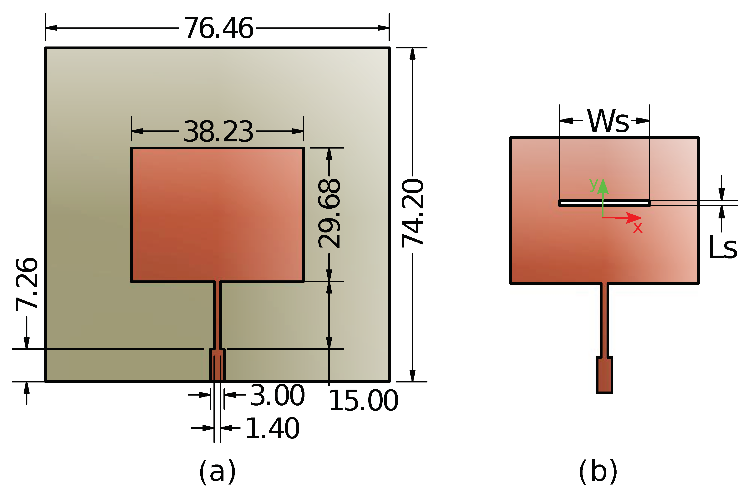
represents the patch width, the effective dielectric constant (taking into account the surrounding space), the patch length extension due to fringing effect, the physical length of the patch, and the speed of light, respectively. We present the geometry of the proposed antenna where the conventional (reference) and the slot-loaded antennas are displayed on
Figure 1a and
Figure 1b, respectively. In order to set the resonant frequency within the ISM radio band, which allows the antenna to handle many medical and industrial applications, we defined
GHz as the operation frequency of the dominant mode (
). The dimensions of the antenna were met by calculating Equations (
1)–(
4). We employed electrical parameters of a fiber-glass laminate substrate FR4 to design the antennas. This material has a nominal dielectric constant
of
, a height
h of
mm, and top and bottom copper cladding thicknesses
t of
mm. Additionally, the feeding line was a microstrip transmission line with a characteristic impedance of
. Therefore, we implemented a Quarter-Wavelength impedance transformer (QWIT) for impedance matching between the antenna and the transmission line, and the input impedance of the antenna model was
[
28]. We modeled the conventional antenna using Computer Simulation Technology (CST), which is a high-performance software for electromagnetic analysis. The fact that the dielectric constant varies as the frequency increases, which occurs in low-cost substrate materials such as FR4, makes us expect the real dielectric value to be different from the nominal value. Hence, it became necessary to establish the actual dielectric constant that would allow the simulation to match the measurements. Therefore, we constructed a first prototype of a conventional patch antenna and then performed a parametric simulation of
. It allowed us to achieve the real dielectric constant
of
, i.e.,
less than the substrate specifications. Based on those results, the dielectric constant
was used in the subsequent simulations. In
Figure 2, we present a comparison between the measurements and the simulation of the reflection coefficient of the reference antenna. This figure includes the electrical response of the antenna with the nominal and fixed dielectric constant both before and after employing the impedance matching technique via QWT.
2.2. Parametric Analysis
This section presents a systematic analysis of impacts of the slot on antenna behavior. Hence, we aim to clarify the influence of the slot on several parameters of the antenna, such as the resonant frequency, the reflection coefficient, and the input impedance. Since the path of the surface current for dominant mode must follow only the y-axis, the slot represents a discontinuity that will disrupt the current flow in that direction. Thus, the surface current and the electric fields are studied to delve into changes in the antenna’s performance.
First, we defined the slot geometry for the initial numerical analysis. As a result, the slot was placed near the origin of the
x-
y coordinates, exactly at
mm and
mm. Additionally, the slot length (
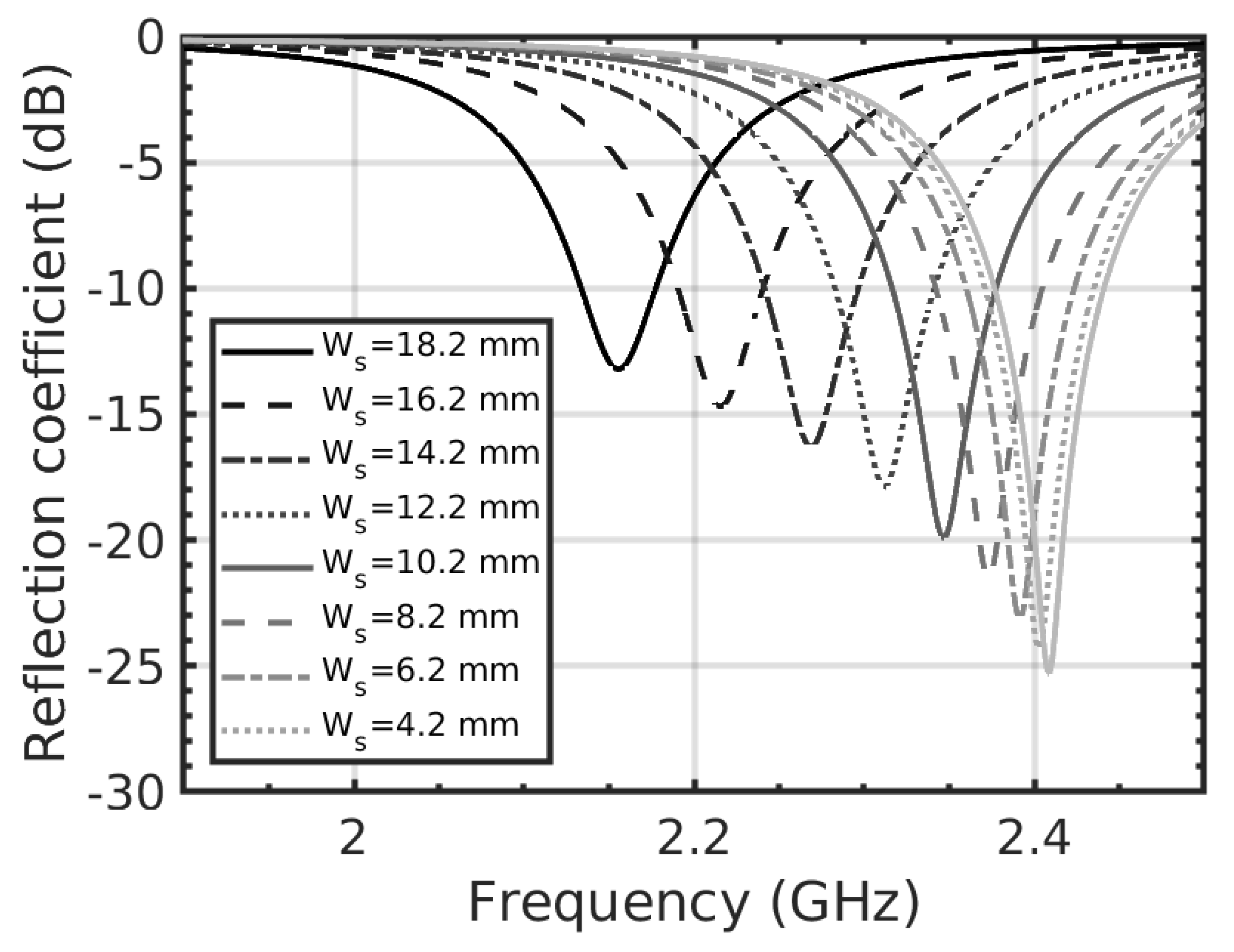
) was defined as a constant 1 mm. Then, a parameter sweep simulation was performed by changing the width of the slot (
) from
mm to
mm, resulting in nine steps. Results suggest a clear trend: both the resonant frequency and the reflection coefficient magnitude are displaced due to an increase in slot width, as shown in
Figure 3. A second parametric simulation was performed with regard to the changes in the
y-position (
) of the slot and the slot width. Here, the slot length and
x-position remained at 1 mm and 0 mm, respectively. We prevented the slot from reaching the radiating edges of the dominant mode
; therefore, values from
mm to
mm in steps of 3 mm (ten steps, and
mm away from each radiating edge) were given to
. For every slot position, we established the slot width
at four different values:
mm,
mm,
mm, and
mm. Overall, there were forty iterations to be performed.
In the third simulation stage, we analyzed changes in input the impedance (), the surface current, and the electric field due to the slot. These analyses were only concerned with variations in the y-slot position, i.e., mm, mm, mm, mm, and mm, whereas the slot width remained fixed at mm. Since the antennas were going to be experimentally connected to a spectrum analyzer through an SMA to N adapter (which increases the transmission line (TL) length), it was necessary to add 7 mm to the LT of the antenna model (only for simulation concerns), bearing in mind that a TL behaves like an impedance transformer. Regarding antennas parameters, we calculated the surface current at non-radiating antenna edges ( mm) and the center of the patch ( mm) for the conventional antenna. Additionally, we calculated the surface current at non-radiating edges ( mm), the slot edges ( mm), and the center of the patch (through the slot mm) for the slot-loaded antenna.
Regarding the electric field, we knew that mode leads to a field configuration only with z-component within the patch antenna cavity. Other field-components are null according the cavity model. We have performed simulation to calculate the electric field within the antenna cavity. In order to do so, the electric field monitor was defined to measure electric field along mm, and considering three slot positions (,, and mm).
2.3. Fabrication and Experimental Setup
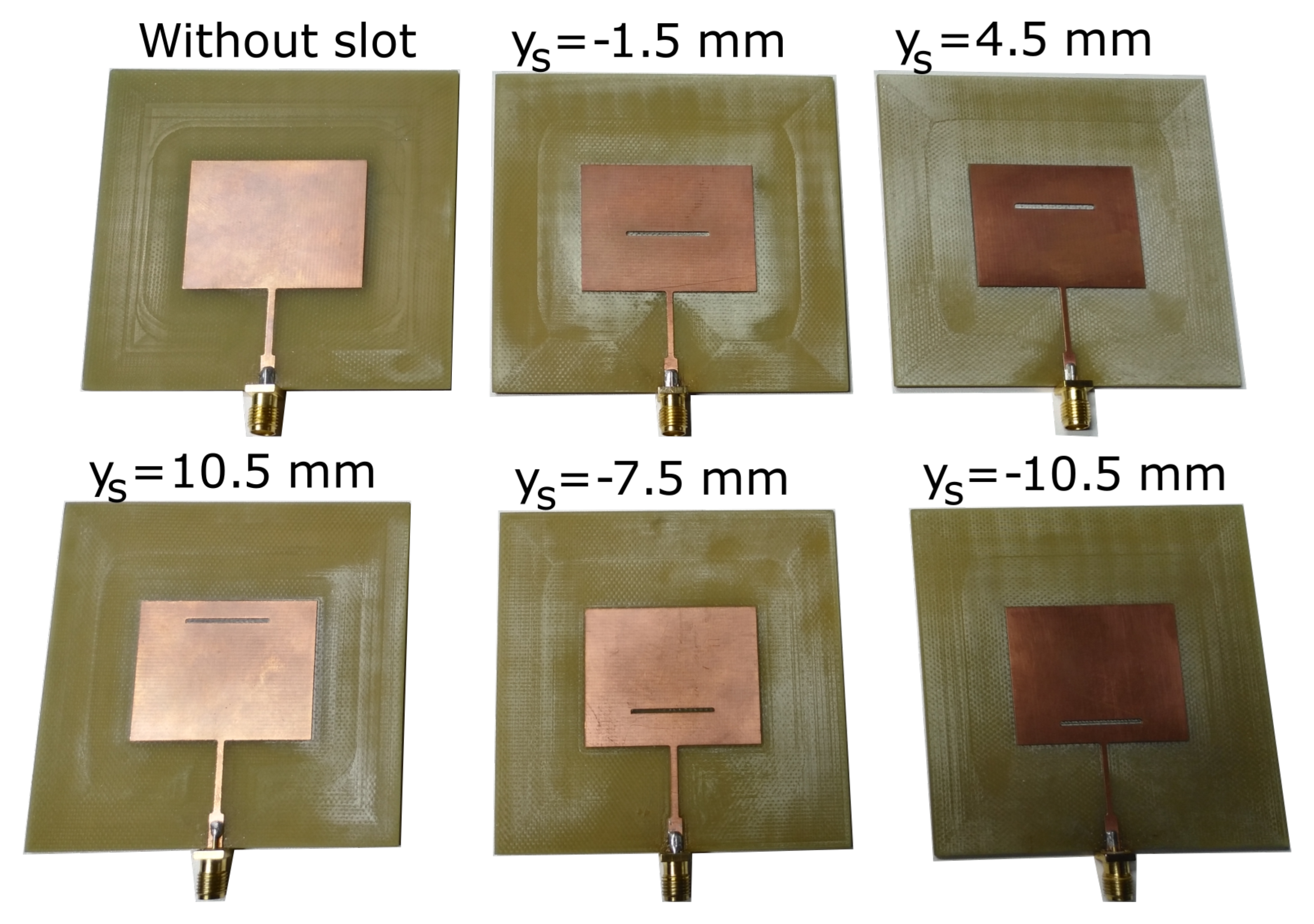
In order to experimentally evaluate the influence of the slot on the behavior of the antenna, five antenna prototypes were constructed. We chose antenna models with the slot
y-positions (
) at
mm,
mm,
mm,
mm, and
mm. So we tried to cover all the slot positions along the patch length. Additionally, the slot width
remained at
mm. To make a comparison, we built a reference antenna (without the slot) as well. The antenna models were saved as G-code commands required for Computer Numerical Control (CNC). In the CNC process, the radiating patches and transmission lines were cut using an end mill of
mm in diameter, and the perimeter was cut using an end drill of 1 mm in diameter. Additionally, for milling, we adjusted the penetration depth to approximately
mm. Therefore, the contours of the radiating patch and the transmission line guaranteed accurate properties such as straight side walls and small penetration depth into the substrate surface. We welded an SMA connector of
of impedance onto each antenna prototype. Subsequently, we connected the antennas to a Vector Network Analyzer (VNA) through an SMA-to-N adapter to take measurements of the resonant frequency, the input impedance, and the magnitude of the reflection coefficient on each antenna. In
Figure 4 and
Figure 5, respectively, we present the manufactured antennas and the experimental set up that we adopted. The following sections compare the results of the simulations and the measurements.
4. Discussion
Prior studies have reported the importance of slot modifications for antenna design; however, they have not provided analytic expressions that describe the impact of such modifications on the reflection coefficient of the antenna. In fact, the most relevant findings of our work are the analytic models presented in Equations (
5) and (
6). Those models describe how the dominant resonant frequency
and the amplitude of the reflection coefficient
change as a function of a parameterization of the slot position and width. Based on those results, we could claim that there are two mechanisms that influence variations in the resonant frequency and the amplitude of the reflection coefficient: (1) the increase in the electrical length and (2) the fluctuation in the input impedance; both due to the slot. Increasing the electrical length makes the resonant frequency shift toward lower values. With all the slot widths, the resonant frequency dropped suggesting an increase in the effective electrical length of the antenna patch.
Remarkably, when the slot was near both radiating edges, it had very little influence on the resonant frequency. In contrast, as the slot approaches the center of the radiating patch, the change in resonant frequency reached its maximum. A reasonable explanation for this behavior might be that the current distribution follows the sine function , which has its maximum in the middle of the patch (). Therefore, when the slot is located around the center of the patch, it represents a significant obstacle for the current path. In contrast, the resonant frequency would have similar value to the antenna without the slot (a rectangular patch) when the slot is located at either the upper or lower radiating edges. Hence, the resonant frequency of the antennas with the slots in their limit positions would be expected to be the same as one of the antenna without the slot.
On the other hand, the variation in the input impedance due to the slot position has a substantial connection with the amplitude of the reflection coefficient of the antenna. Negative slot y-positions influence larger variations in the input impedance (real and imaginary part), which cause the reflection coefficient to increase. On the contrary, as the slot y-position becomes positive, i.e., close to the second radiating edge, the tries to return to its reference value (antenna without the slot).
Regarding the electric field and the surface current, the slot produced abrupt changes in the path of the surface current, which changes the electric field configuration. So, around the slot there exist not only x and y, but also a z-component of the electric field. We deem that those results are a consequence of the changes in the surface current path due to the slot and the high current concentration around it.
Based on the cavity model applied to patch antennas, it is known that there exists only a z-component of the electric field within the cavity, which has a distribution described by cos(pi*x/L). Therefore, the strongest z-component of the electric field would be around the radiating edges (
and
) of the patch, and a slot placed in such a position would have a high influence on the electric field. On the contrary, a slot placed around the middle of the patch (
) would have minimal influence on the electric field. Since there is a relationship between the electric field and the resonant frequency of the patch antenna, the aforementioned trade-off between the electric field and the slot position could be extended to the relation between the slot position and the resonant frequency. In fact, our results showed that the shift of resonant frequency is proportional to a cosine function, as is shown in Equation (
5). Our results can be helpful to the improved understanding of modified antennas design for improving applications such as gain enhancement [
29], phase correction [
30], and beamsteering [
31].
As indicated previously, the model in Equation (
5) represented shifts in the frequency as the initial resonant frequency
plus a harmonic function perturbation. We found a parallel situation regarding the amplitude of reflection coefficient: its changes obeyed the
value of the original antennas plus a harmonic and an exponential function perturbation. Moreover, Equations (
5) and (
6) establish that those models can be used to find specific electrical parameters of a patch antenna without using any numerical software that implements a more complex solution method (such as finite elements) and requires expensive hardware resources and long execution times.
Although Equation (
5) does not involve physical parameters such as capacitance and inductance of the slot, it does accurately describe the experimental results taking into account the geometric characteristics of the slot, and it is an important parameter in antenna design. Furthermore, the slot describes the modifications in the Ez component of the electric field within the antenna (
Figure 11), which in turn control the resonance frequency (and other parameters,
Figure 12,
Figure 13 and
Figure 14). On the other hand, the proposed model can provide relationships beyond the known analytical models and take into account new parameters like the slot width and length that are not addressed in conventional models. Moreover, the model corresponds to the experimental results with almost negligible error, and it reaches results similar to those found with the models of transmission lines and resonant cavities, i.e., in the case when the dimensions of the slot approach zero.
In addition, our results addressed some interesting questions regarding slot antenna analyses asked by (Joler, 2015), which confirm the importance of understanding the relationship between the frequency and antenna parameters such as the length, width, or position of the slot.
5. Conclusions
This paper discussed the influence of slot parameter variations on the resonant frequency, reflection coefficient amplitude, and input impedance of a patch antenna. Analytical models of the influence of the slot on the rectangular microstrip patch antenna were developed, which was the main goal of this study. Those models allowed us to calculate the resonant frequency of the dominant () mode and the amplitude of the reflection coefficient of a slotted antenna with several slot positions and widths. The proposed models were verified using measurements which showed good agreement. Additionally, the models enabled a reliable and quick computation of the antenna’s parameters using a simple calculation.
The resonant frequency, reflection coefficient amplitude, surface current, and electric field distribution of the slotted antenna depend on the slot position. When the slot is at its upper limit, the resonant frequency and the amplitude of the reflection coefficient tend to be the same as those of the antenna without the slot. In addition, the resonant frequency of the slotted antenna and the reference antenna are alike even when the slot is at its lower limit (nearby the feeding edge). Regarding the reflection coefficient, it becomes maximum when the slot is near the feeding edge, which results in a major impedance mismatch. In every position, the slot presents an obstruction for the surface current path, which influences increments in the electrical length, changes in the resonant frequency, and the occurrence of new electric field components.


