Abstract
This paper provides a novel methodology for designing implanted multiple-input and multiple-output (MIMO) antennas in the automatic fashion. The proposed optimization consists of two sequential phases for firstly configuring the geometry of an implanted MIMO antenna and then sizing the design parameters through the hierarchy top-down optimization (TDO) and regression deep neural network (DNN), respectively. It tackles the difficulty in constructing the structure of antennas and also provides optimal values for the determined variables, sufficiently. This methodology results in valid electromagnetic (EM)-verified post-layout generation that is ready-to-fabricate. The effectiveness of the proposed optimization-oriented method is verified by designing and optimizing the implanted MIMO antenna in the frequency band of 4.34–4.61 GHz and 5.86–6.64 GHz suitable for medical applications at the emerging wireless band. For our design, we employ the actual biological tissues as bone, liquid (%1 sodium chloride, %40 sugar in distilled water), and plexiglass surroundings with a bio-compatible substrate, as aluminium oxide on a large ground plane, that is suitable to be used in a particular biomedical applications involving smart implants.
1. Introduction
Future wireless medical technologies are expected to explosively grow for controlling the bodily functions and to gather the data of different physiological parameters [1]. Over the last decade, implanted devices, especially implanted antennas, have got the attention of researchers due the compatible connection between the patient and physical doctors [2,3]. Multiple-input, multiple-output (MIMO) antennas are commonly used in the wireless communication systems due to the advanced capability in supporting data even under interference situations [4,5]. Hence, designing MIMO antennas that can be used for medical communication services can be a very good solution to increase the accuracy of the system.
Due to the complexity of MIMO antennas, it is not straightforward to model and design these circuits, and optimization-based approaches are importantly required. Reported various optimization methods around radio frequency and antenna designs are particle swarm optimization [6,7], ant colony optimization [8,9], chicken swarm optimization [10], harmony search algorithm [11], and genetic algorithm [12]; however, when the design parameters are in a huge number these methods can not be successful and intelligent based optimization methods are required [13].
Recently, machine learning and deep learning proved their talents in optimizing radio frequency designs and they can be a good solution for modeling and optimizing MIMO antennas [14]. They can model the complex designs by considering the relationships between the input and output data that in turn can be design parameters and/or design specifications, respectively [15].
This paper presents an automatic methodology for designing and optimizing implanted MIMO antennas; to the best of authors’ knowledge, the proposed method is for the very first time reported in the literature. This optimization-oriented process is performed by using two sequential methods as hierarchy top-down optimization (TDO) and regression deep neural network (DNN) for configuring the antenna geometry and sizing the design parameters, respectively. The TDO method is employed for constructing the general structure of the antenna and the DNN, a multi-layer neural network, with long short-term memory (LSTM) layers is used for predicting the optimal design parameters more accurately than the shallow neural networks (SNNs) [16]. As constructing the accurate DNN is significant, bayesian optimization (BO) is applied for determining the optimal hyperparameters. All the optimization process is executed in the environment where Microwave Studio (Dassault Systèmes) and numerical analyzer as MATLAB are working concurrently. The proposed method leads to generate electromagnetic (EM)-verified post layout generation and dependency on designers’ experiences is substantially reduced. Moreover, the difficulty of modeling and sizing complex design of implanted MIMO antenna is solved to the most highest degree.
This paper is organized as follows: Section 2 in a nutshell, presents the proposed methodology for modeling and sizing the implanted MIMO antennas. Section 3 is devoted to explain the practical construction of the proposed method, while Section 4 describes the simulation results of optimized antenna. Finally, Section 5 concludes this work.
2. Proposed Optimization Method
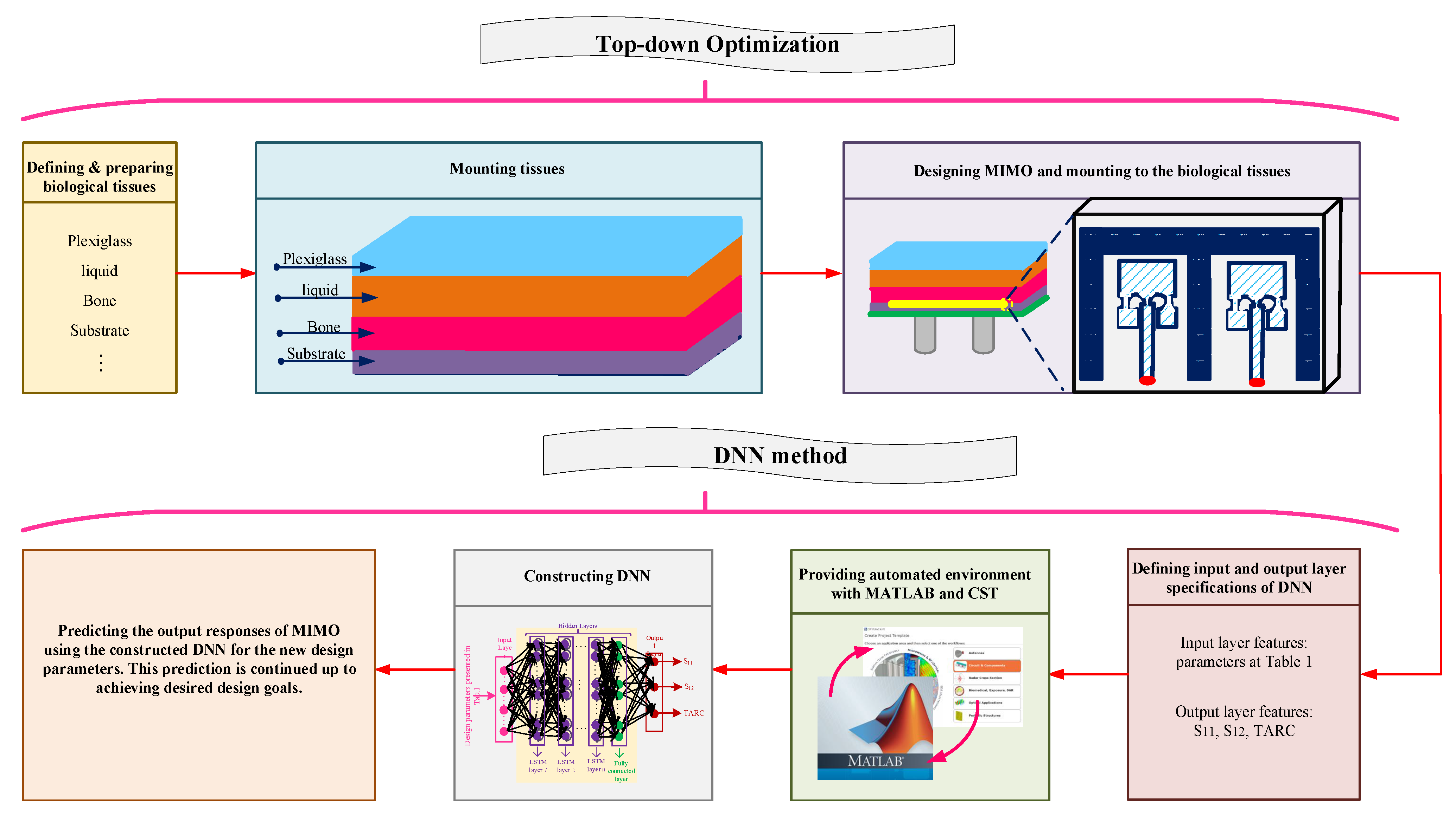
The proposed optimization-oriented algorithm consists of two sequential phases: (i) constructing the initial configuration of implanted MIMO antennas by employing the hierarchy TDO method, and (ii) optimizing the included design parameters using the regression DNN where LSTM layers are employed. This section provides comprehensive explanations about the used two sequential methods for modeling and sizing the implanted MIMO antennas, automatically. Algorithm 1 (at the end of this section) briefly summarizes the employed optimization methods and the comprehensive flowchart of the proposed method is summarized in Figure 1.
| Algorithm 1: Automatic methodology for optimizing implanted MIMO antennas using sequential TDO and DNN methods |
Phase I (TDO method) 1: Define the biological tissues and define the dielectric properties of each tissue; 2: Mount all the tissues over together with the sequence of bone, liquid, and plexiglass; 3: Design the MIMO antenna on the substrate and ground planes; Phase II (DNN method) 4: Determine the design parameters and specifications of the MIMO configuration; 5: Run parametric sweep for achieving the training and testing dataset for constructing DNN; 6: Achieve the optimal hyperparameters of the hidden layer using the BO method; 7: Train the LSTM-based regression DNN; 8: Predict the optimal design parameters by using the trained DNN. |
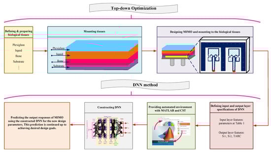
Figure 1.
Comprehensive graphical representation of the proposed method.
2.1. Top-Down Optimization for Configuring the Implanted MIMO Antenna
Providing the initial configuration for sizing the design parameters of antennas, especially implanted antennas, is an important task due to the complexity of designs. Hence, a strong method is required for designing and analyzing complicated designs. The top-down method is a hierarchy method where the design is broken into the smaller parts [17]. As the implanted antennas are the hierarchical designs, the TDO method can be an effective solution in generating the initial configuration.
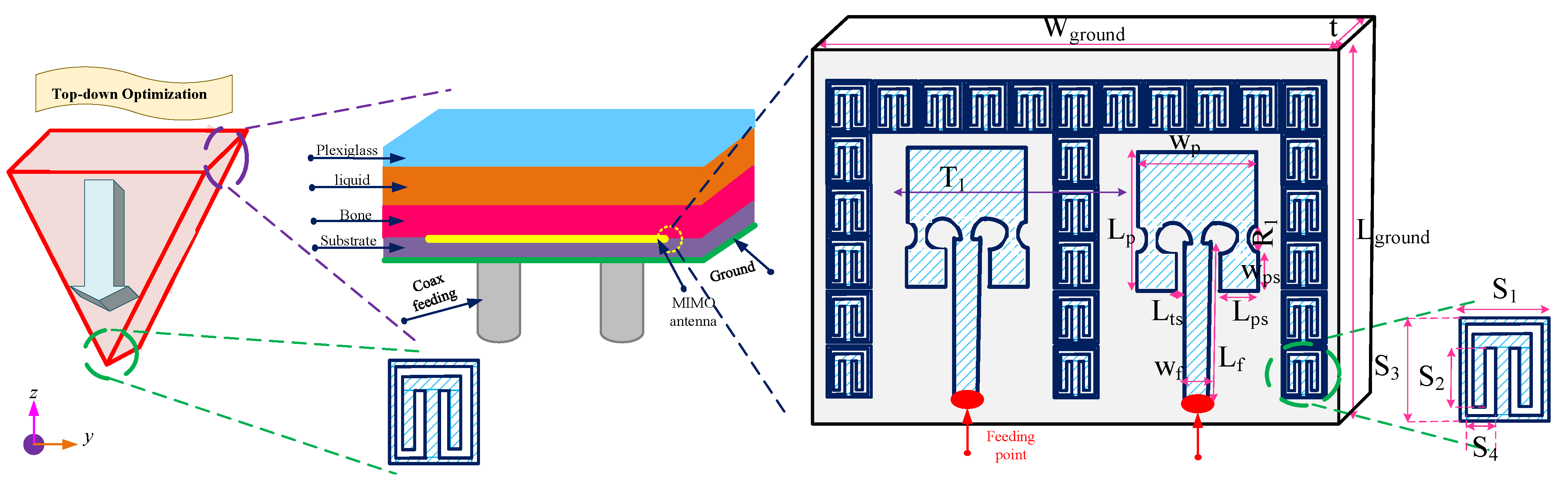
Figure 2 presents the hierarchy TDO method for generating the initial configuration of the implanted MIMO antenna. In this paper, we aim to design implanted MIMO antennas where biological tissues or their equivalent are mounted over them (Step-1). For top-optimization, the biomedical tissues as ‘bone’ and ‘liquid’ are employed that are covered by a ‘plexiglass’ layer (Step-2). Then the MIMO antenna is designed by setting the single antennas, feeding structures, substrate and ground plane. Afterwards, in the bottom-optimization phase, any small partitions of MIMO antenna are arranged in order. Thus, this method tackles the difficulty of constructing the complex geometry of antenna designs and provides the initial configuration for sizing the design parameters (Step-3).

Figure 2.
Hierarchy top-down optimization for configuring the implanted MIMO antenna geometry (width and length are in mm; drawing not in scale).
2.2. Regression DNN for Sizing the Design Parameters of Implanted MIMO Antenna
After generating the initial structure of the implanted MIMO antenna, determining the optimal design parameters is crucial leads to enhance their performance. For this case, deep learning approach is employed due to its suitable accuracy in modeling and predicting the various employed variables in the complex designs [16].
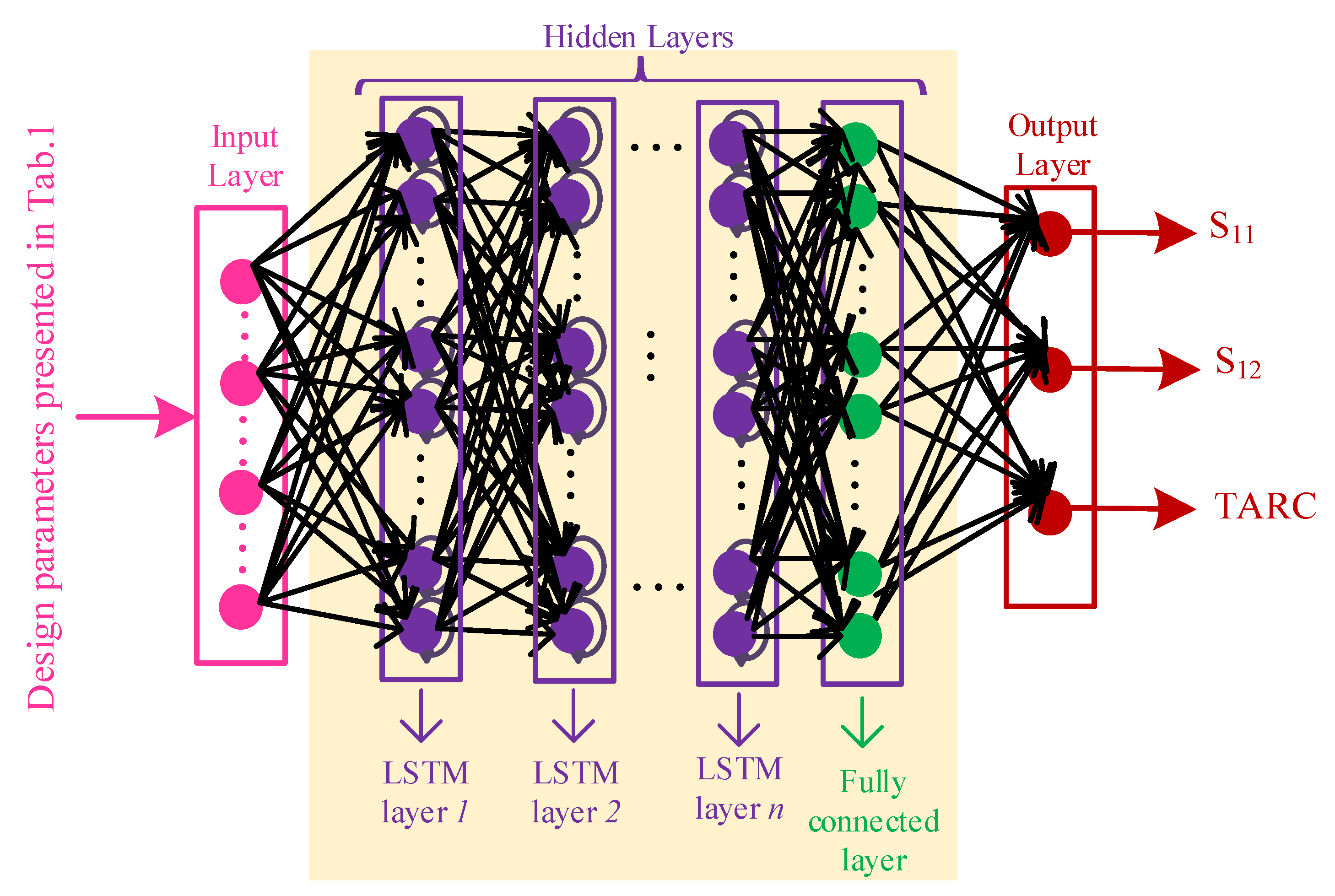
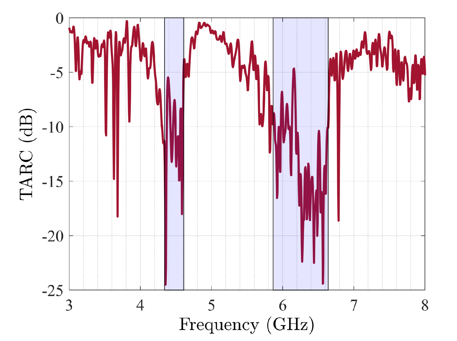
Figure 3 presents the proposed regression DNN in sizing the constructed implanted MIMO antenna in Section 2.1. As it is shown, each DNN structure includes input layer, hidden layers, and output layer. For our problem, the input layer features include the various design parameters presented in Table 1 and the output layer features predict the scattering parameters (S-parameters) and total active reflection coefficient (TARC) specifications in a large bandwidth (Step-4). The TARC is one the main characteristics used in MIMO designs which presents the total incident power to the total outgoing power as Equation (1) defines for zero phase weighting [18].
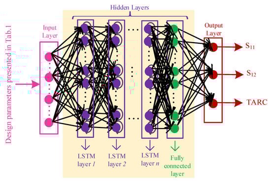
Figure 3.
Regression DNN for predicting the best design parameters of implanted MIMO antenna.

Table 1.
Design parameters of optimized implanted MIMO antenna in Figure 2.
Lastly, the hidden layers are constructed using the LSTM layers where the optimal hyperparameters are determined using the BO [19] for predicting the optimal number of layers and neurons.
For training any DNN, suitable amount of dataset including training, validation, and testing data is needed that can be achieved, for example, by running a parametric sweep. For this case, firstly the initial constructed antenna is generated in the CST Studio Suite (Dassault Systèmes). Then, an automated environment is created that is the collaboration of CST and numerical analyzer as MATLAB. CST has two important duties as (i) providing the output responses for the simulated design parameters and also (ii) preparing the outcome file includes all the simulation input and results. MATLAB collects all the input data namely as , , and and also the corresponding output data (, , and ). The training, validation, and testing data is split with the range of 70%, 15%, and 15%. This amount of data is generated by employing the Latin hypercube sampling technique [20] within the and range of current points achieved from the initial MIMO design in (Step-3) (Step-5). The input feature of optimization are the ones presented in Table 1 and the output features of optimization are the , , and TARC specifications that are collected by MATLAB. Afterwards, the hyperparameters of the regression DNN include number of neurons and number of LSTM layers are determined using the BO method (Step-6). For the proposed optimization method, the used activation function and loss function are the rectified linear unit (ReLU) and mean squared error, respectively. in the following, the DNN is constructed using the ‘trainNetwork’ function in the MATLAB environment (2).
After training the DNN, for ensuring about the accuracy of the network, the ‘predict’ function is used to measure the difference between the actual and the predicted output through the constructed DNN as (3) that is expected to be more than 90% (Step-7).
Finally, the constructed DNN is used for predicting the design parameters and optimizing the MIMO design up to achieving the optimal solutions (Step-8).
3. Practical Implementation of the Optimization-Oriented Method
The presented automatic methodology is employed in the CPU execution environment: it involves an Intel Core i7-4790 CPU @ 3.60 GHz with 32.0 GB RAM. As described in Section 2, firstly the TDO method is used for constructing the initial antenna geometry. For this case, sequentially biological tissues as: bone, liquid like %1 sodium chloride (NaCl) and %40 sugar dissolved in distilled water, and plexiglass are mounted over together. Then aluminium oxide (Al2O3) substrate with large ground plane are placed for constructing the MIMO antenna. The dielectric properties of tissues can be obtained from [21,22].
After constructing the various tissues and planes, the MIMO antenna must be generated. Figure 2 shows the general structure of MIMO configuration considered in this paper. It consists of two single antennas with transform distance surrounded by a 1-D periodic ring series around and in between the patch antennas. These rings are considered aiming to reducing the surface waves, hence the mutual coupling between the single patches. The ground plane has a large extension of 150 mm and 120 mm, along x and y directions, respectively. Such a dimension guarantees eliminating the diffraction effects that would not be present for a conformal configuration, when the antennas are bend around a medical implant.
In the second phase, the regression DNN that is constructed by the LSTM layers is utilized for predicting the optimal design parameters of constructed initial antenna design. The total obtained datset consists of 1000 sequences where each sequence includes multi-segment , and TARC values over the operation bandwidth. The optimal hyperparameter achieved from BO method represents n = 3 LSTM layers with 50 neurons in each layer. As the capability of each DNN is validated by the training/testing accuracy, the normalized training error for the regression DNN is around 0.09.
4. Simulation Results of the Optimized Implanted MIMO Antenna
This section presents the simulated output of the optimized implanted MIMO antenna using the TDO and DNN methods. Sequentially, the biological layers are mounted together and the MIMO antenna is placed on Al2O3 substrate. Afterwards, the proposed and trained DNN is employed for sizing the implanted MIMO antenna that are optimized in terms of S-parameters and TARC specification. Table 1 presents the achieved optimal design parameters for the configured antenna.
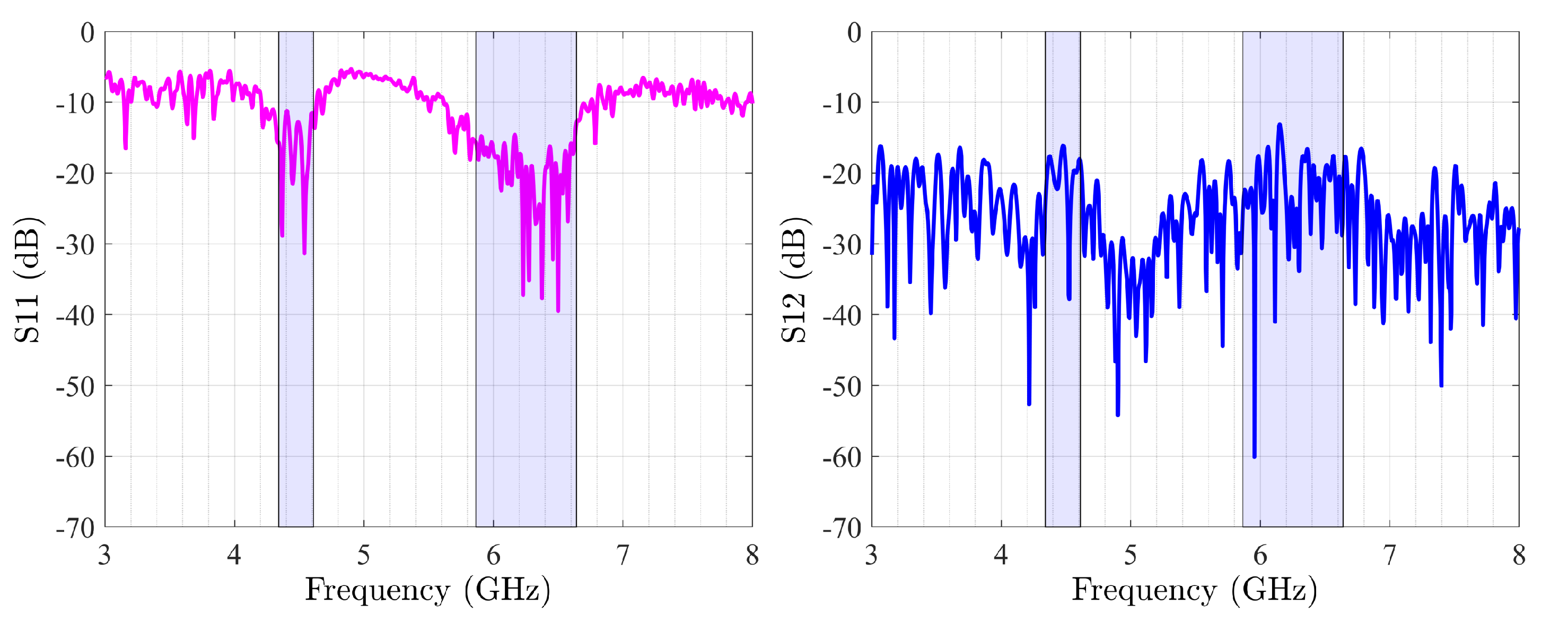
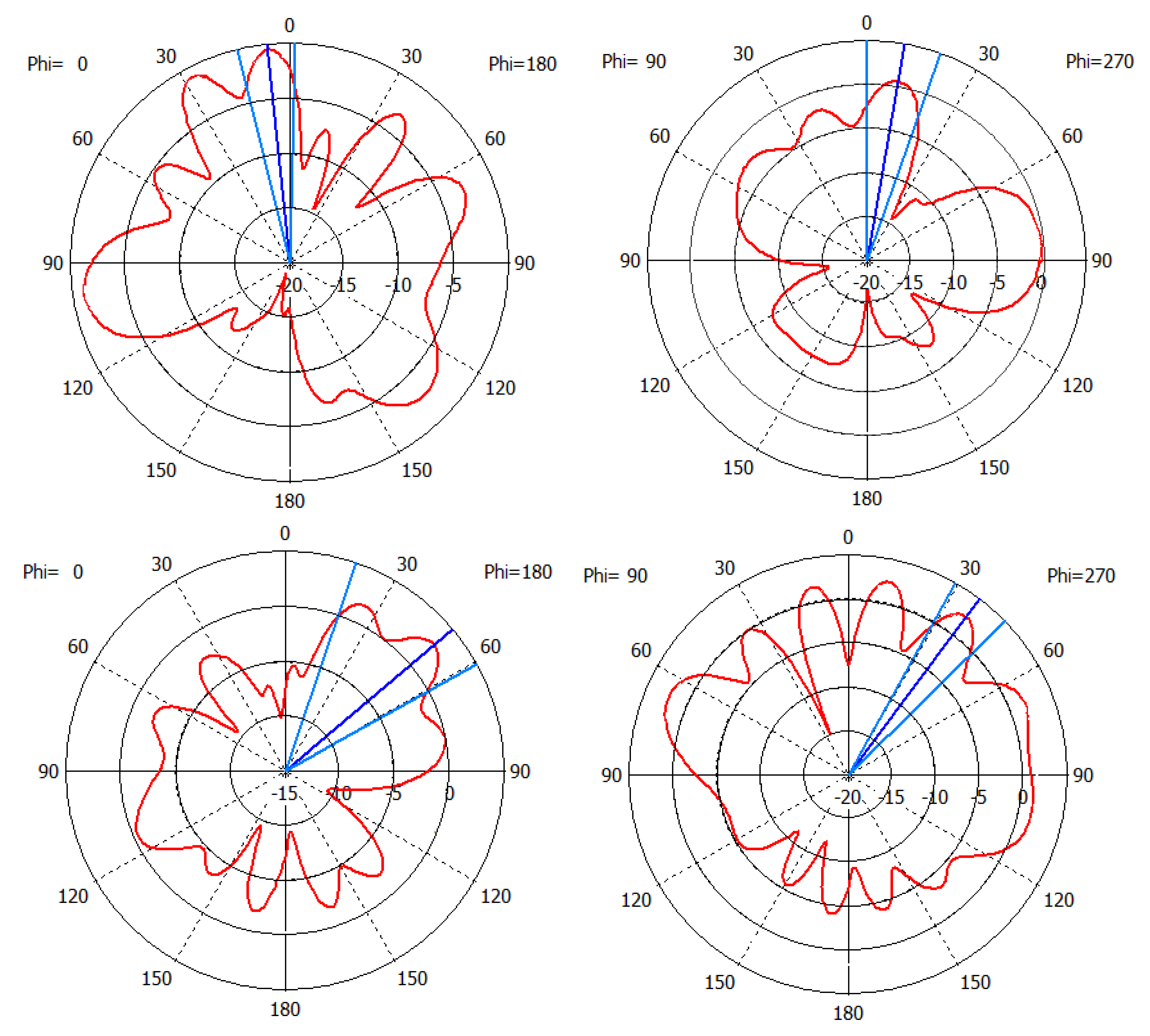
The presented MIMO antenna covers the two frequency bands of 4.34–4.61 GHz and 5.86–6.64 GHz. Figure 4 presents the output results of optimized antenna in terms of S-parameters. Another important specification of the implanted MIMO antenna is TARC: it is less than −10 dB in the two mentioned frequency bands. Figure 5 reports the obtained TARC value. The radiation pattern (co-pol term) of optimized antenna in the E- and H planes are depicted in Figure 6 for the centered frequencies of the two bands, i.e., 4.5 GHz and 6.2 GHz. The plots correspond to excitation of both ports with equal amplitude. Effects of the variable coupling between the antennas (even if low, see Figure 4 (right)) can be observed, that is further influenced by the dispersive behaviour of the resonators around them. Additionally, the variation of the frequency in the wide range—almost 50% (from 4.5 GHz to 6.3 GHz)—corresponds to a change in the relative () normalized distance, that in turn will affect the radiation pattern. In the present investigation, aiming to demonstrate the validity of the optimisation process, no attention has been paid to the effect of the ground plane, since in a further step the antennas will be positioned on a cylindrical/conical configuration, hence eliminating any diffraction effects from the finite dimension ground plane present here [23,24]. The reported value of the gain of the embedded MIMO antenna can be considered in case of link budget estimation.

Figure 4.
(left) and (right) of optimized implanted MIMO antenna array.
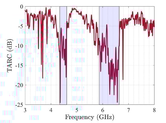
Figure 5.
TARC of optimized implanted MIMO antenna.
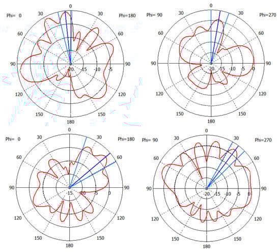
Figure 6.
Co-pol radiation pattern of the considered antenna in the E—(left) and H—(right) planes at 4.5 GHz (top) and 6.2 GHz (bottom).
5. Conclusions
Designing and optimizing high performance antennas, especially the implanted antennas with MIMO structure are not straightforward and require challenging efforts. For the first time, this study presents a novel optimization-oriented method for modeling and sizing the implanted MIMO antennas, automatically. Intelligent methods are proposed in this work for firstly building the initial configuration and then sizing the implanted MIMO using the TDO and DNN methods, sequentially. All process are performed automatically with the combination of CST and MATLAB. The superior performance of the proposed method is validated by designing an implanted MIMO antenna in the multi frequency band from 4.34 GHz to 4.61 GHz and from 5.86 GHz to 6.64 GHz that are emerging wireless bands for future medical applications. The optimized MIMO antenna to be used within the human body in these emerging wireless medical bands are firstly proposed in the present work.
Our proposed optimization paradigm is flexible and it can be developed by: (1) considering various biomedical tissues, (2) using various types of feeding points, (3) employing different optimization methods in configuring the initial structure of the MIMO antenna.
Author Contributions
Conceptualization, L.M. and L.K.; methodology, L.K.; software, L.K.; validation, L.K., L.M. and I.P.; formal analysis, L.M.; investigation, L.K.; resources, L.M. and I.P.; data curation, L.K.; writing—original draft preparation, L.K.; writing—review and editing, L.K., L.M. and I.P.; visualization, L.K.; supervision, I.P. and L.M.; project administration, L.M. and I.P.; funding acquisition, I.P. All authors have read and agreed to the published version of the manuscript.
Funding
This work was partially supported by a grant of the Romanian Ministry of Education and Research, CNCS—UEFISCDI, project number PN-III-P4-ID-PCE-2020-0404, within PNCDI III.
Conflicts of Interest
The authors have no conflict of interest.
References
- Ahmed, I.; Halder, S.; Bykov, A.; Popov, A.; Meglinski, I.V.; Katz, M. In-Body Communications Exploiting Light: A Proof-of-Concept Study Using Ex Vivo Tissue Samples. IEEE Access 2020, 8, 190378–190389. [Google Scholar] [CrossRef]
- Magill, M.K.; Conway, G.A.; Scanlon, W.G. Circularly Polarized Dual-Mode Wearable Implant Repeater Antenna With Enhanced Into-Body Gain. IEEE Trans. Antennas Propag. 2020, 68, 3515–3524. [Google Scholar] [CrossRef] [Green Version]
- Soliman, M.M.; Chowdhury, M.E.H.; Khandakar, A.; Islam, M.T.; Qiblawey, Y.; Musharavati, F.; Zal Nezhad, E. Review on Medical Implantable Antenna Technology and Imminent Research Challenges. Sensors 2021, 21, 3163. [Google Scholar] [CrossRef] [PubMed]
- Usman, M.; Kobal, E.; Nasir, J.; Zhu, Y.; Yu, C.; Zhu, A. Compact SIW Fed Dual-Port Single Element Annular Slot MIMO Antenna for 5G mmWave Applications. IEEE Access 2021, 9, 91995–92002. [Google Scholar] [CrossRef]
- Mendoza, H.A.; Corral-Briones, G. A Three Dimensional MIMO Channel Model for Unmanned Aerial Vehicle in Urban Environments. IEEE Open J. Commun. Soc. 2021, 2, 1419–1430. [Google Scholar] [CrossRef]
- Budhu, J.; Rahmat-Samii, Y. A Novel and Systematic Approach to Inhomogeneous Dielectric Lens Design Based on Curved Ray Geometrical Optics and Particle Swarm Optimization. IEEE Trans. Antennas Propag. 2019, 67, 3657–3669. [Google Scholar] [CrossRef]
- Jarufe, C.; Rodriguez, R.; Tapia, V.; Astudillo, P.; Monasterio, D.; Molina, R.; Mena, F.P.; Reyes, N.; Bronfman, L. Optimized Corrugated Tapered Slot Antenna for mm-Wave Applications. IEEE Trans. Antennas Propag. 2018, 66, 1227–1235. [Google Scholar] [CrossRef]
- Zhu, D.Z.; Gregory, M.D.; Werner, P.L.; Werner, D.H. Fabrication and Characterization of Multiband Polarization Independent 3-D-Printed Frequency Selective Structures With UltraWide Fields of View. IEEE Trans. Antennas Propag. 2018, 66, 6096–6105. [Google Scholar] [CrossRef]
- Rajo-Iglesias, E.; Quevedo-Teruel, Ó.; Inclan-Sanchez, L. Mutual Coupling Reduction in Patch Antenna Arrays by Using a Planar EBG Structure and a Multilayer Dielectric Substrate. IEEE Trans. Antennas Propag. 2008, 56, 1648–1655. [Google Scholar] [CrossRef]
- Liang, S.; Fang, Z.; Sun, G.; Liu, Y.; Qu, G.; Zhang, Y. Sidelobe Reductions of Antenna Arrays via an Improved Chicken Swarm Optimization Approach. IEEE Access 2020, 8, 37664–37683. [Google Scholar] [CrossRef]
- Zhang, F.; Jia, W.; Yao, M. Linear Aperiodic Array Synthesis Using Differential Evolution Algorithm. IEEE Antennas Wirel. Propag. Lett. 2013, 12, 797–800. [Google Scholar] [CrossRef]
- Han, Q.; Zhang, Y.; Yang, Z.; Long, W.; Liang, Z. Antenna Array Aperture Resource Management of Opportunistic Array Radar for Multiple Target Tracking. IEEE Access 2020, 8, 228357–228368. [Google Scholar] [CrossRef]
- Mir, F.; Kouhalvandi, L.; Matekovits, L.; Gunes, E.O. Automated optimization for broadband flat-gain antenna designs with artificial neural network. IET Microwav. Antennas Propag. 2021, 15, 1537–1544. [Google Scholar] [CrossRef]
- Gao, D.; Guo, Q.; Eldar, Y.C. Massive MIMO as an Extreme Learning Machine. IEEE Trans. Veh. Technol. 2021, 70, 1046–1050. [Google Scholar] [CrossRef]
- Gragnaniello, D.; Bottino, A.; Cumani, S.; Kim, W. Special Issue on Advances in Deep Learning. Appl. Sci. 2020, 10, 3172. [Google Scholar] [CrossRef]
- Jin, J.; Zhang, C.; Feng, F.; Na, W.; Ma, J.; Zhang, Q. Deep Neural Network Technique for High-Dimensional Microwave Modeling and Applications to Parameter Extraction of Microwave Filters. IEEE Trans. Microw. Theory Tech. 2019, 67, 4140–4155. [Google Scholar] [CrossRef]
- Supalov, A.; Semin, A.; Klemm, M.; Dahnken, C. Top-Down Software Optimization. In Optimizing HPC Applications with Intel® Cluster Tools; Apress: Berkeley, CA, USA, 2014; pp. 39–53. [Google Scholar] [CrossRef] [Green Version]
- Chae, S.h.; Kawk, W.i.; Park, S.O.; Lee, K. Analysis of mutual coupling in MIMO antenna array by TARC calculation. In Proceedings of the 2006 Asia-Pacific Microwave Conference, Yokohama, Japan, 12–15 December 2006; pp. 2090–2093. [Google Scholar] [CrossRef]
- Greenhill, S.; Rana, S.; Gupta, S.; Vellanki, P.; Venkatesh, S. Bayesian Optimization for Adaptive Experimental Design: A Review. IEEE Access 2020, 8, 13937–13948. [Google Scholar] [CrossRef]
- Mckay, M.; Beckman, R.; Conover, W. A Comparison of Three Methods for Selecting Values of Input Variables in the Analysis of Output From a Computer Code. Technometrics 1979, 21, 239–245. [Google Scholar] [CrossRef]
- Calculation of the Dielectric Properties of Body Tissues. Available online: http://niremf.ifac.cnr.it/tissprop/htmlclie/htmlclie.php. (accessed on 4 July 2021).
- Kanda, M.; Ballen, M.; Chou, C.K.; Balzano, Q. Formulation and Characterization of Tissue Simulating Liquids Used for SAR Measurement (500–2000 MHz) (invited). In Proceedings of the 2001 Asia-Pacific Radio Science Conference, Tokyo, Japan, 1–4 August 2001; p. 274. [Google Scholar]
- Matekovits, L.; Huang, J.; Peter, I.; Esselle, K.P. Mutual Coupling Reduction Between Implanted Microstrip Antennas on a Cylindrical Bio-Metallic Ground Plane. IEEE Access 2017, 5, 8804–8811. [Google Scholar] [CrossRef]
- Matekovits, L. On the radiation mechanism of implanted antennas with large conformal ground plane. IET Microwav. Antennas Propag. 2017, 11, 1765–1769. [Google Scholar] [CrossRef]
Publisher’s Note: MDPI stays neutral with regard to jurisdictional claims in published maps and institutional affiliations. |
© 2021 by the authors. Licensee MDPI, Basel, Switzerland. This article is an open access article distributed under the terms and conditions of the Creative Commons Attribution (CC BY) license (https://creativecommons.org/licenses/by/4.0/).