Article

Robust Hybrid Beam-Forming for Non-Orthogonal Multiple Access in Massive MIMO Downlink

1
Department of Computer Engineering, College of Computers and Information Technology, Taif University, P.O. Box 11099, Taif 21944, Saudi Arabia
2
Electrical Engineering Department, Higher Colleges of Technology, Ruwais Campus, Abu Dhabi 12389, United Arab Emirates
*
Author to whom correspondence should be addressed.
Electronics 2022, 11(1), 75; https://doi.org/10.3390/electronics11010075
Submission received: 18 November 2021 / Revised: 20 December 2021 / Accepted: 23 December 2021 / Published: 27 December 2021
(This article belongs to the Section Microwave and Wireless Communications)

Abstract

:
This paper presents hybrid precoding for a non-orthogonal multiple access (NOMA) transmission scheme in a millimeter wave (mmWave) massive MIMO (mMIMO) downlink. In hybrid precoding, the analog precoder is obtained by the orthogonalization of the users’ channel vectors to minimize inter-beam interference. The digital precoder consists of a zero-forcing precoder to minimize inter-user interference. In order to break the barrier of one user per beam, we utilize the NOMA within the beam for power domain multiplexing among users. Simulation results show the proposed scheme’s efficacy compared to the state-of-the-art schemes and provide 1.48 times better sum-rate performance at 10 dB received SNR.

1. Introduction

The huge demand for various services and the rapid growth of mobile Internet and Internet of Things (IoT) applications have led to research on fifth-generation (5G) communication systems [1]. There are two prominent frequency bands in 5G communications: the millimeter wave (mmWave) frequency band and the sub-6 GHz frequency band. By operating at 30–300 GHz, mmWave communication may provide orders-of-magnitude higher bandwidths than sub-6 GHz band communication. Hence, the fifth-generation (5G) wireless communication requirement for high throughput motivates the wireless industry to use mmWave communication for its vast bandwidth advantage [2]. Aside from the wide bandwidth, the smaller wavelengths in mmWave allow more antennas to be packed into the same physical space, allowing vast multiple-inputs multiple-outputs to be supported more effectively in mMIMO [3,4]. This also introduces spatial multiplexing and diversity gains. In fact, it has been shown that mmWave-mMIMO can increase system capacity by orders of magnitude [5].
However, the implementation of mmWave mMIMO in practice still faces challenges [6]—to fully exploit the gains provided by mMIMO, each antenna needs a dedicated radio frequency (RF) chain. Due to space limitations, it is challenging to implement mMIMO systems. However, the mmWave frequency range made it possible, as at such high frequencies, the antenna size is drastically reduced. Many antennas also result in an equal number of RF chains, which are too expensive and power-hungry. The user equipment (UE) and the base station (BS) use phased array beamforming technology to solve this problem. Beam-forming is a technique that can control an array of antennas to transmit radio signals in a specific direction. Antenna arrays using beamforming not only transmit power or signals in all directions but also determine the direction of interest and send and receive more substantial signal beams in that specific direction [7].
The beamforming architecture is mainly divided into digital beamforming, analog beamforming, and hybrid beamforming [8]. In digital beamforming, amplitude/phase shift keying is applied to the digital signal (digital to analog converter (DAC)) at the transmitting end. The opposite process is done after analog to digital converter (ADC) and digital downlink converter (DDC) operations; digital beamforming includes RF translators, A/D conversion, DDC, complex weight multiplication, and a summing function. In comparison to digital beamforming, analog and hybrid beamforming architectures can minimize the number of RF chains by combining analog or mixed analog-digital signal processing. In particular, analog beamforming is usually implemented using phase shifter networks and is one of the simplest ways to apply MIMO in mmWave systems. However, its performance is affected by the quantitative phase shift and lack of amplitude matching. Hybrid beamforming (HB) combines analog and digital beamforming; it uses each benefit and may acquire excellent stability among system complexity and overall performance by accurately deciding on various RF chains. Hybrid beamforming is classified into partially connected HB architectures and fully connected architectures, as shown in Figure 1. The partially connected HB uses a separate subset of a phase shifter and antenna array with each RF chain. Because of the structure, this is also called sub-array hybrid beamforming. In fully connected HB architecture, the RF beamformer of each RF circuit uses all antennas; this is where the RF signals from various RF circuits are combined before being sent through the antennas. Due to the architecture, this type is also called full array HB [9]. In a fully interconnected architecture, additional RF aggregation components can cause failures and performance losses, and it is one of the main problems of mmWave radio. On the other hand, the partial connection architecture of the RF chain allows fewer antennas to be accessed, which leads to severe shortcomings such as large beam widths, fewer directions, and significant interference from other chains. They try to reduce the interference to the partially connected HB type. The partial connection architecture provides a simpler circuit and lower loss than the fully connected architecture [6,9]. The fully-connected structure provides a more significant array gain.
The maximum number of users that mmWave mMIMO can handle falls as the number of RF chains decreases. Non-orthogonal multiple access (NOMA) has recently been added to mmWave mMIMO to break this essential restriction and expand the number of concurrently supported users [10,11]. NOMA, unlike traditional orthogonal multiple access (OMA), uses superposition coding and successive interference cancellation (SIC) to allow several users to access the same time-frequency resource [12,13]. Furthermore, because of the very directed nature of mmWave transmission, the usage of NOMA in mmWave is advantageous since the users’ channels can be strongly linked [14].
In heterogeneous networks, NOMA has proven to be a promising technique to increase the performance of multi-tier networks. A two-tier network consists of Macro-base stations (MBS) and small-base stations (SBS). Parihar et al. [15] examined the use of cooperative NOMA to achieve SWIPT in heterogeneous networks. Further, [16] provides unique time slotting solutions that attempt to boost the throughput of weak users while ensuring user fairness, which is especially important as the number of users in a NOMA group rises. The coexistence of multi radio access technology (RAT) with ultra-high frequency SBS and mmWave SBS layers in heterogeneous networks is studied in [17]. At the SBS level, NOMA is employed to handle a high number of users. To establish the order of the users for NOMA, the SBS must obtain the user’s CSI. Getting CSI with SBS is challenging since the number of users significantly increased. The suggested approach employs double-restricted feedback from the user. The first is for user orders, while the second is for selecting the appropriate RAT. A three-tier NOMA is employed in a heterogeneous cellular network that includes an MBS layer, a Femto base station (FBS) tier, and a device-to-device (D2D) tier, with NOMA being used in the FBS and D2D levels [18]. Reference [19] presents a smarter HetNet with an MBS and FBS layer. The FBS layer is equipped with NOMA and carrier sensing support for its transmissions. Carrier detection helps reduce interference by preventing base stations within a specific transmitter range from broadcasting and increasing performance.
The sparse massive MIMO channel has few multipath components, and the channel matrix is ill-conditioned [20]. This study aims to investigate a low complexity hybrid precoding for a non-orthogonal multiple access (NOMA) transmission scheme in a real-World ill-conditioned mmWave massive MIMO downlink. The remainder of this paper is structured in the following manner. Section 2 presents related work. The system, signal and channel model are covered in Section 3. In Section 4, the proposed energy-efficient massive MIMO-NOMA is discussed. The proposed hybrid beamforming NOMA algorithm is explained in Section 5. The simulation results are presented in Section 6. Finally, Section 6 includes a conclusion.
Notations: Bold upper/lower case letters denote vectors and matrices, respectively. The notations X 1 , X T , X H , and t r ( X ) denote the inverse, transpose, Hermitian (conjugate transpose), and trace of a matrix X . d i a g p is the diagonal entries of a matrix P , | | is the cardinality of set   , M × N denotes the set of all M × N matrices with complex entries, and C N ( μ , σ 2 ) is the circularly symmetric complex Gaussian distribution with mean μ and variance σ 2 . All the acronyms are defined in Table 1.

2. Related Work

Reference [21] proposes and investigates a multi-beam NOMA strategy for the mmWave mMIMO system and also studies its resource allocation systems. Each radio frequency chain utilizes a beam splitting mechanism to create several analog beams to serve diverse NOMA consumers. The proposed approach may enable NOMA transmission for users with arbitrary departure angles, unlike the traditional mmWave-NOMA technology, which can only support multiple users in a single beam. This gives NOMA in mmWave communications more flexibility, allowing it to take advantage of the possible multi-user diversity. The authors devised a suboptimal two-stage beam-user allocation strategy in order to optimize the system’s sum rate. To optimize the conditional system sum rate in the first stage, a user grouping and antenna allocation technique based on coalition formation game theory were used with known analog beamforming. The second stage employs the ZF digital precoder to solve a nonconvex optimization problem for the power allocation with the objective of optimizing the system sum-rate while taking quality-of-service constraints into account. A beam splitting system provides many analog beams for NOMA transmission to satisfy distinct clients; instead of the present mmWave orthogonal multiple access (mmWave OMA) systems, the suggested solution might service numerous users on each RF chain. Unlike the conventional mmWave-NOMA method, which can accommodate multiple NOMA users inside the same beam, the suggested system may execute NOMA transmission for users with any AoD distribution. This increases the flexibility of NOMA, allowing it to better exploit the potential for multi-user diversity. The simulation results demonstrated that, in each stage, the intended resource allocation might provide near-optimal results. This multi-beam NOMA scheme is designed under the assumption of sparsely populated users such that there is a very low probability that two or more users come under the same beam. The beam gain is also decreased when one RF chain is associated with two or more spatially apart users. In addition, the beam width is increased with the reduced number of antennas per RF chain.
A user categorization technique based on channel gains and correlations is suggested in [22]. Joint hybrid beamforming and power allocation problems are devised to optimize the possible sum rate. To tackle this issue, first they form users’ groups using the K-means method and then they find a power allocation method for arbitrary fixed hybrid beamforming. They use a boundary-compressed particle swarm optimization technique to solve the analog beamforming issue and use the zero-forcing form to construct the digital beamforming to reduce inter-group interference. To begin addressing this nonconvex problem with high-dimensional variables, the authors obtain the power allocation solution for arbitrary fixed hybrid beamforming, which is divided into intra-group and inter-group power allocation. Then, using the approximation zero-forcing technique, they create the digital beamforming to decrease inter-group interference given arbitrarily set analog beamforming. To implement NOMA with HBF, it utilizes the K-means algorithm and the normalized channel correlation for the users’ grouping. Users with low channel correlation are assigned to the same group, while users with high channel correlation are assigned to separate groups, significantly lowering interference between groups of users. After that, the power allocation and HBF design problem is formulated to optimize the users’ average sum rate, with each user having a minimum rate constraint. This paper does not discuss inter-beam interference and suffers from a higher computational complexity.
The author of [23] considers that each user uses analog-only beamforming, whereas the BS uses a combination of analog and digital beamforming. Several users can share the same beam via the NOMA technique to achieve a higher cumulative capacity. However, because distinct localized users’ analog beamformers are used, the BS’s digital beamformers are not fully aligned with the users’ baseband effective channels. Several users may be allocated similar or even identical beamformers. Meanwhile, a user pairing and power allocation mechanism is developed to minimize interference from other beams and increase the aggregate capacity. After users’ pairing, it uses a matched filter based analog beamformer, which is simple but it may suffer from inter-group interference, whereas our proposed scheme provides orthogonal beams which eliminate the inter-group interference.
Wei et al. [24] eliminate the antenna allocation part from [21] by increasing the beamwidth to accommodate more users in a NOMA group. More crucially, by extending the beamwidth, the suggested beamwidth control may increase the number of serviced NOMA groups, thus maximizing the energy efficiency benefit provided by NOMA. Two beamwidth control approaches are given to this purpose, one based on conventional beamforming and the other on Dolph–Chebyshev beamforming. The authors first analyze the primary lobe power losses caused by the two beamwidth management approaches and suggest an efficient analog beamformer design to reduce the power loss. This paper investigates a non-orthogonal multiple access (NOMA) technique based on beamwidth management. The proposed technology permits various customers in a single NOMA set to share the same radio frequency chain and analog beam for superposition transmission. In this article, a beamwidth control approach is investigated to overcome the physical limits of the narrow analog beam by extending the diameter of the analog beamwidth to smooth the construction of NOMA clusters. The authors then discuss the suggested bandwidth control’s significant lobe power loss and derive the asymptotically optimum analog beamformer from enhancing the system’s sum in the antenna bulk mode. The recommended beamwidth control-based NOMA strategy is compared against a baseline scheme that uses time division multiple access to determine overall system improvements (TDMA). The authors focus on a simple method for adjusting the beamwidth of an analog beam by turning off some antennas to achieve this goal. To maximize the system sum-rate in a wide variety of antennas regimes, they designed the asymptotically optimal analog beamformer after studying the significant lobe power loss related to beamwidth management. However, widening the beam width causes inter-group interference. Though the proposed scheme has less computational complexity than [21], it suffers from low user diversity gain. Table 2 shows the summary of the related work.

Contribution

In this paper, we develop robust hybrid beamforming for NOMA-based millimeter-wave massive MIMO systems. We focus on the joint advantage of the low complexity analog precoding and system capacity enhancement using NOMA-mMIMO system. We use a real-World mmWave mMIMO channel with a strong LOS component. For this type of channel, it is extremely difficult to get the channel inversion matrix. This type of channel matrix is called an ill-conditioned channel matrix. We use the Householder orthogonalization method to get the analog precoding matrix as it has minimum orthogonality error with the ill-conditioned matrix. We use the stronger user channel vector as the group channel vector, which eliminates the inter-group interference in NOMA groups. The contributions of this paper are summarized as follows:
  • Robust hybrid beamforming is designed by using the House-holder based channel orthogonalization method. The above-mentioned related works use either SVD-, EVD-based analog beams, or the fixed beam structure (DFT). Though DFT-based analog beamforming is simple, and many researchers used DFT-based fixed analog beamforming, but this further requires a computation-intensive beam-user pairing process.
  • We use the strongest user’s channel vector as the group channel. In the case of the ill-conditioned channel matrix, the proposed scheme provides low orthogonality error and renders almost orthogonal analog beams. Due to the orthogonal beams, inter-group interference is eliminated.
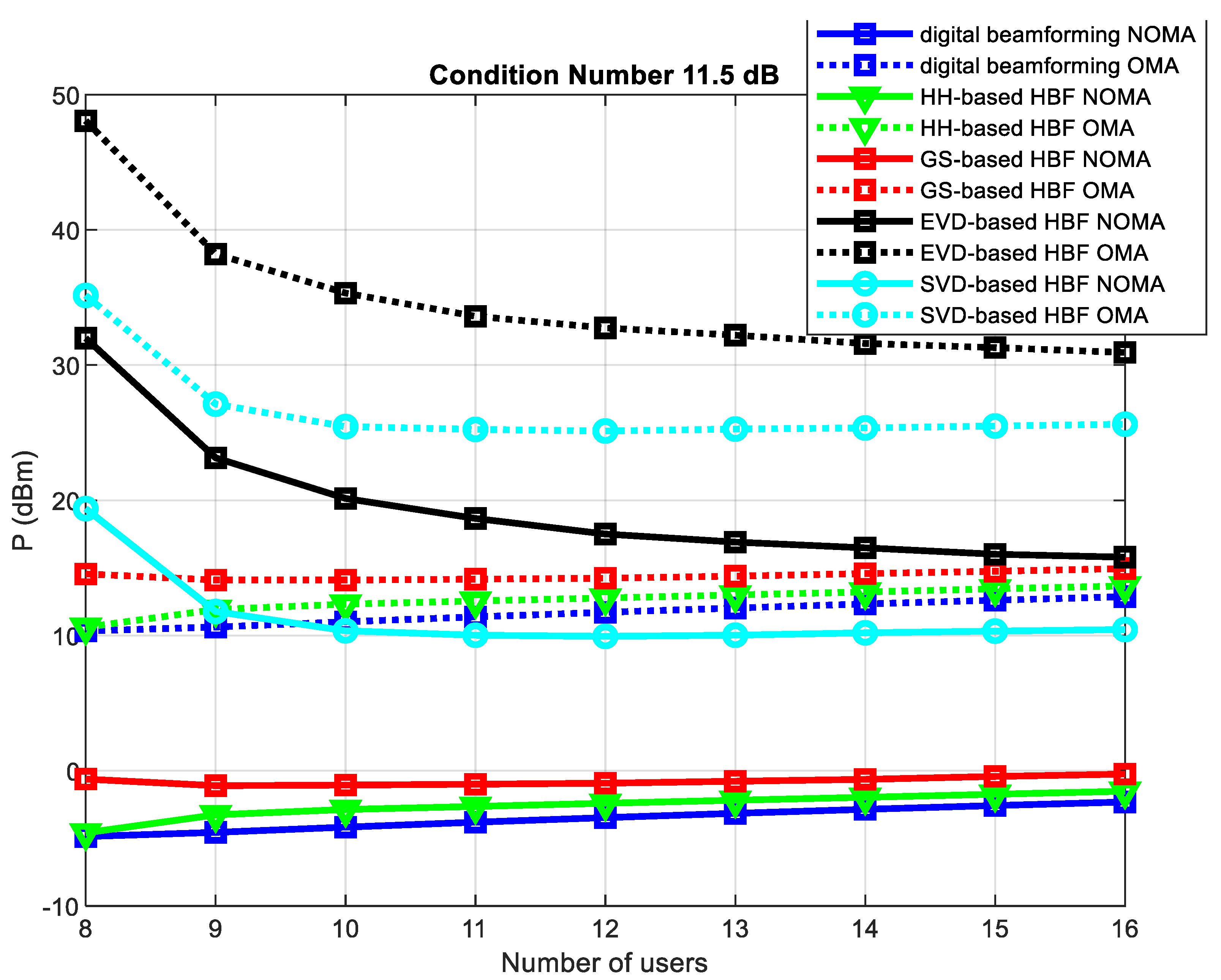
  • Simulation is performed in the more realistic wireless environment, which is controlled by the channel matrix condition number. It can be seen that the proposed scheme requires less transmit power to guarantee the users’ target spectral efficiency as compared to the SVD, EVD, and GS-based NOMA-mMIMO schemes.

3. System, Signal, and Channel Model

This section presents the system, signal, and channel model for the proposed massive MIMO hybrid beamforming and NOMA downlink system.

3.1. System and Signal Model

In the conventional multiuser MIMO systems, the combined received signal
y = [y1, y2, …, yK] T can be expressed as:
y = HH FPS + v,
where s = [s1, s2, …, sK ]T is the K × 1 transmitted signal for all K users with normalized power E(ssH)= IK, P = diag{p} is the total transmitted power for K users and
p = [√(p1),√(p2),…,√(pK)],
satisfies K = 1 K p k   P (the maximum transmitted power at the BS), F = [f1, f2, …, fK ] is the Nt × K beamforming matrix with ‖fk2 = 1 for k = 1,2,…,K, and v is the AWGN noise with zero mean and variance σ 2 , that is, 𝒞𝒩(0, σ2IK). H = [h1, h2, …, hK] of size Nt × K is the channel matrix, where hk of size Nt × 1 denotes the MIMO channel vector between BS and kth user. Finally, the superscript H is a Hermitian matrix, which is a complex square matrix that is equal to its own conjugate transpose of the channel matrix (H). Particularly, in this paper, we consider the widely used Saleh–Valenzuela channel model for the mmWave communication, which is explained in the following subsection.
The number of needed RF chains at the BS in conventional MIMO systems is equal to the number of transmit antennas, that is, NRF = Nt, which is typically huge for a MIMO systems, for example, NRF = Nt = 256. As a result, due to high hardware costs and energy consumption caused by RF chains, the conventional implementation of massive MIMO at mmWave frequencies is prohibitive. Each RF chain, for example, consumes roughly 250 mW, and a mmWave massive MIMO system with 256 antennas requires 64 W. To overcome this problem, the concept of beam space MIMO was recently used, in which a lens antenna array is used to minimize the required number of RF chains in mmWave large MIMO systems to reduce the power consumption.
The lens antenna array’s role is to realize the spatial domain analog beamforming using Nt × Nt discrete Fourier transform matrix U, as follows:
U = [ a ( θ ¯ 1 ) ,   a ( θ ¯ 2 ) ,   ,   a ( θ ¯ N t ) ] H ,
where θ ¯ N t = 1 N t ( n N t + 1 2 ) for n = 1, 2, …, Nt are the fixed spatial directions. Then, the received signal vector y ¯ can be represented as:
y ¯ = H ¯ F P s + v ,
where the channel matrix H ¯ is defined as:
H ¯ = U H = [ U h 1 ,   U h 2 ,   , U h k   ] = [ h ¯ 1 , h ¯ 2 , , h ¯ K ] ,
where h ¯ K = U h k   is the beam domain channel vector of the kth user.
Then,
y ¯ = H H U H F P s + v .
There are Nt beams with spatial directions θ ¯ 1 ,   θ ¯ 2 ,   ,   θ ¯ N t as each row of the beam domain channel matrix H ¯ in (5), corresponds to one beam. At mmWave frequencies, there is a limited scattering and most of the NLoS component die after a few reflections, therefore, the number of NLoS components which actually reach the receiver is much smaller than the number of beams, that is, L   N t . Since, there are only a few dominant elements in each beam domain channel vector h ¯ K , therefore, the beam domain channel matrix H ¯ is a sparse matrix. The beam selection algorithm exploits this sparse structure to design reduced-dimension beam domain MIMO systems without significant performance loss. Because of the sparse nature of the beam domain channel matrix, we can use some beam selection algorithm to select K out of Nt beams to serve K users at the same time. Then, we can write the received signal in (6) as:
y ¯ = H ¯ B H F B P s + v ,
where H ¯ B     | | × K is the reduced-dimension beam domain channel matrix after the beam’s selection, and is the set of selected beams. F B of the size |   | × K is the reduced-dimension beamforming matrix. By exploiting the sparse nature of the mmWave channel, we can have a significantly reduced number of required RF chains, and we need only NRF = |   | RF chains. Existing beam domain MIMO systems, on the other hand, can only handle one user at a time. As a result, the maximum number of users in a given frequency resource cannot exceed the number of RF chains, that is, K ≤ NRF, which is the ultimate bound of beam domain MIMO systems. This is because the DoF required by users must be less than or equal to the DoF of RF chains; otherwise, the linear operation would fail to separate signals for different users. To solve this constraint, we propose a new joint analog precoding and beam selection approach that combines NOMA and massive MIMO in the following section.

3.2. Channel Model

The extended Saleh–Valenzuela mathematical model is used to simulate the mmWave Channel because, mathematically, it precisely captures the propagation pattern found in mmWave channels [25]. Let there be NC scattering clusters around the transmitter and receiver, such that every cluster produces Lp multipath components [26]. At mmWave frequencies, the electromagnetic propagation waves exhibit high vapor absorption and low penetration strength; therefore, there are limited multipath components in each cluster u ∈ {1, …, NC} and a dominant line-of-sight (LOS) wave propagation. When scattering clusters are randomly situated, measurements have shown that the Saleh–Valenzuela model is a good fit for describing the random behavior of the MPC’s amplitude, phase and arrival delay in the mmWave channel [27]. Empirical measurements show that the mmWave channel fits the extended Saleh–Valenzuela model [28]. The Nt x 1 channel vector of user 𝑘 can be written as in [29]:
h k = N t N C L p + 1       u = 1 N C l = 0 L p   α k u , l   a ( ϕ k U , l ) e j 2 π u n / N t   ,
where j = √−1, α k u , 0 and α k u , l , l = 1, …, Lp represent the complex gain of the LOS, l = 0 path, and non-line-of-sight (NLOS), l = 1, …, Lp paths are independent and identically distributed with 𝒞𝒩 (0,1) in cluster 𝑢, respectively. a is the transmit array response vector. The variable ϕ k U , l is the azimuth angles (the aiming angle in the array) of arrival in cluster u [30] for user 𝑘 with uniform distribution, ϕ k U , l ~𝒰 (−π/2, π/2). The transmit steering vector can be expressed as:
a ( ϕ k U , l ) = 1 N t   [ exp ( j 2 π d λ   sin ϕ k U , l   i ) ] i ϵ I ( N t ) T ,
where I(Nt) = {i−(Nt−1)/2, i = 0, 1, …, Nt−1} is the set of indices [31], λ is the wavelength of the propagation waves and d is the spacing between the antenna elements at the base-station. At the end, we get the general channel matrix H of the multiuser MIMO system as, H = [h1, ……, hk] ∈ 𝕔NtxK.

4. Proposed Energy-Efficient Massive MIMO-NOMA

In the proposed MIMO-NOMA method, unlike previous mMIMO systems, more than one user per beam can be serviced concurrently, as shown in Figure 2. In simple massive MIMO beamforming, each beam is produced by an RF chain, and beam selection methods such as maximum magnitude (MM) [21] and signal-to-interference-plus-noise-ratio (SINR) maximization [7] can be used to choose one beam for each user. It is worth mentioning that there is a high probability that different users choose the same beam, a phenomenon known as “conflicting users” in this type of problem.
In a typical mmWave mMIMO system with Nt = 128 antennas and K = 16 users and the uniformly distributed spatial directions, the chance of users picking the same beam is 62.4% [32].
Unlike existing large MIMO systems, which use user scheduling to select only one user from a group of competing users, the proposed MIMO-NOMA system can serve conflicting users simultaneously using the same RF chain. Despite the fact that the beam selection algorithm can select the beams up to NRF, the number of concurrently serviced users, K, can be greater than NRF, that is, K ≥ NRF. Let Sn be the set of users served by the nth beam for n = 1, 2, …, NRF and one user can be served by only one beam, that is, Si ⋂ Sj = Φ for i ≠j and n = 1 N R F | S n | = K . After beam selection for the mth user in the nth beam, the NRF×1 beam domain channel vector is represented by hm,n, and NRF×1 fn shows the uniform precoding vector for users in the nth beam. We can assume that h 1 , n H   f n 2   h 2 , n H   f n 2         h | S n | , n H   f n 2   f o r   n = 1 ,   2 ,   ,   N R F . The received signal at the kth user in the nth beam can be expressed as:
  y k , n = h k , n H   J = 1   N R F I = 1 | S j | f j p i , j s i , j   + v k , n
= h k , n H f n p k , n   s k , n desired   signal   + h k , n H   f n   i = 1 m 1   p i , n   s i , n + h k , n H   f n   i = k + 1 | S n |   p i , n   s i , n     intra beam   interferences + h k , n   H j   n   i = 1 | S j | f j p i , n s i , j i n t e r b e a m   i n t e r f e r e n c e + v k , n n o i s e ,
where pk,n is the transmitted power and sk,n is the transmitted signal for the kth user in the nth beam, and vk,n is the AWGN noise with zero mean and variance σ 2 . In order to apply SIC decoding at the receiver, more power is allocated to the user with a low channel-to-noise ratio (CNR), and less power is allocated to the user with a high CNR. The user with a high CNR first decodes the signal of a low CNR user and then removes that signal from the composite received signal to get its signal. The low CNR user directly decodes its signal while considering the other user’s signal as simple noise. In the case of two users in a NOMA group with sorted CNR as C N R 1 > C N R 2 , then, the power allocation would be p 1 < p 2 . Note that in existing beam domain MIMO systems, only one user can be supported in each selected beam, that is, |Sn| = 1(n = 1, 2, …, NRF), whereas in the proposed MIMO-NOMA system, |Sn| can be larger than one for n = 1, 2, …, NRF.
In Equation (11), the precoding vectors { f n } n = 1 N RF should be cautiously designed to minimize the inter-beam interferences. Due to the NOMA, intra-beam interferences are induced by the power domain multiplexing of users within a beam [33,34]. It can be suppressed by conducting SIC in the order of increasing equivalent channel gains, that is, by performing SIC, the kth user in the nth beam eliminates the interferences from the ith user ( i > k) in the nth beam. In massive MIMO systems, NOMA allows more than one user to be serviced at the same time within each beam, and this allows us to schedule the number of users greater than the number of selected analog beams, that is, K ≥ NRF. In the suggested MIMO-NOMA system, however, users are subjected to interferences from other beams in addition to intra-beam interferences. As a result, in practice, a simple combination of NOMA with MIMO cannot ensure consistent performance and precoding; power allocation should be devised to minimize interferences by maximizing the sum spectral efficiency.
Digital beamforming of the system model is given by:
H e f f = F R F   h k F B B = H e f f ( H e f f H H e f f + I ( K ) ) 1 .
Calculating hybrid beamforming of the model based on the Householder method is given by:
F H B F = F R F   F B B .
The received SINR at user k in beam n is given by:
S I N R k , n = p k , n | h k , n H f n | 2 | h k , n H   f n   | 2 i = 1 m 1   p i , n + | h k , n H   f n   | 2 i = k + 1 | S n |   p i , n + | h k , n   H | 2 j   n   i = 1 | S j | f j p i , n + σ v 2  
and the total power transmit power is given by:
P = n = 1 N k = 1 K n 2 ( R t a r g e t ) 1 S I N R k , n ,
where K n is the number of users in beam n, and Rtarget is the target information rate per user.
The system sum rate is given by:
R s u m = n = 1 N k = 1 K n log 2 ( 1 + P k , n S I N R k , n ) .
The Proposed Hybrid Beamforming Noma Algorithm
The steps of the proposed algorithm are described in detail as follows:
(1)
The algorithm initializes first the parameter values of the users and channel.
(2)
Compute the channel matrix of the mmWave massive MIMO systems.
(3)
A zero-forcing precoder is used to calculate the mmWave digital beamforming to minimize interference between users.
(4)
Calculate the analog beamforming using different mathematical methods to minimize the inter-beam interference by orthogonalization of the user’s channel vectors.
(5)
Add both analog and digital beamforming to get hybrid beamforming.
(6)
This paper adds NOMA into beam domain mmWave massive MIMO systems to further enhance spectrum efficiency and connectivity density. Unlike the existing beam domain MIMO system, two or more users can be simultaneously accommodated within each selected beam in Algorithm 1.
Algorithm 1. Low Complexity Hybrid Beamforming with NOMA
Input: Channel State Information, Total power
Output: carrierToNoiseRatio, PowerAllocated of analog and digital beamforming
1 Initializes NOMA parameter values: Nt, K, NRF, subChannels, bandwidth, initial Power
2 Calling mmWave channel model function:
2.1. Calling Initialize function.
2.2. Generate hk→(Nt × 1)-dimension for each user k
2.3. Implementing NOMA (i.e., two pathloss value to get users with different channel gain in each beam):
   For 1 to length of user group (ρk)
    hk = sqrt(Nt/(Ls × ρk (i))) × (ak × (z.T));
2.4. Get desired condition number
CondNumb = 10 × sqrt(2); →Desired condition number
For 1to length of user group (ρk)
Singular value decomposition of the channel matrix (h(Nt × K))
H = U × S × VT
3 Initialization: assign zero to variable SINR
4 Calling House Holder function:
Input: Channel model or channel matrix
Output: Analog beamforming and digital beamforming
4.1. Initialize parameters →assign zero to analog and digital matrix
4.2. Find the reflector:
4.3. Apply Householder reflection to each column of A (channel matrix) and Q (identity matrix of Nt): i.e., Nt is the number of antennas and K number of the user.
for j from 1 to K
A = A(k to Nj)−v × (2 × (vT × A(k to Nj)));
end
for j from 1 to Nt
Q = Q(k to N j)−v × (2 × (vT × Q(k to Nj)));
end
4.4. Computing Analog Beamforming (FRF):
Q = QT;
R = upperTriangular(A);
Qtrancated = Q(1 to K);
for i from 1 to K
for j from 1 to N
FRF = (1/sqrt(Nt)) × (Qtrancated(j,i)/sqrt(Qtrancated(j,i) × Qtrancated(j,i)T);
end
end
4.5.  Computing Digital Beamforming (FBB):
FBB using Equation (12)
5 Calculate hybrid beamforming-based householder (FHBF):
FHBF using Equation (13)
6 Initialization→assign zero to Sum Rate (Rsum).
7 Calculate carrier to noise ratio (SINR):
For k to users (K)
Assign interference to zero→interference = 0
Assign noise to some value→noise = 10 6
SINRk = (abs(FHBF(k)T × hk(k)))2 (SINR);
end
8 Compute the transmit power for target rate (P (dBm)):
P using Equation (15)
9 Compute Sum Rate (Rsum):
Rsum using Equation (16)
Computational complexity: For a N t × K channel matrix, the SVD operation has a complexity of O ( N t K 2 ) . The SVD is required to include the desired condition number in the real-world channel realization. The Householder orthogonalization based analog beamformer and user grouping complexity is O ( 2 N t K 2 2 K 3 3 ) . The ZF-based digital precoder requires matrix multiplication and matrix inversion operations with the complexity O ( N t K 2 + 2 K 3 ) and O ( K 3 ) , respectively. Hence, the complexity of the above algorithm is of the order of O ( 2 N t K 2 2 K 3 3 ) .

5. Simulation Results

The suggested low complexity hybrid beamformer based on the Householder function (HHHBF) is assessed in this section. The proposed scheme is compared with the Gram–Schmidt-based hybrid beamforming (GSHBF), eigenvalue decomposition-based hybrid beamforming (EVDHBF), and singular value decomposition-based hybrid beamforming (SVDHBF) in terms of transmit power performance against the target SE. The digital-only beamformer for both NOMA and OMA are also included in the graphs as a benchmark.
We examine a single cell with Nt = 128 uniform linear array (ULA) antenna elements and NRF = 8 RF chains on the base station and K = 16 single-antenna users. The inter-element distance in the ULA is λ/2, where is the transmission wavelength. The ill-conditioned MIMO channel matrix is described using the logarithmic condition numbers 0 dB and 11.5 dB. In the simulations, the number of multipath components L = 5 is used. The findings are achieved by averaging over 1000 channel realizations in simulation.
Figure 3 depicts the transmit power required to achieve the desired target SE in a well-conditioned massive MIMO channel. The required transmit power increases with the increasing target SE. The dotted-line graphs are for various OMA schemes, and the solid lines are for the NOMA schemes. It can be seen that all NOMA have low power consumption as compared to the respective OMA schemes for a target SE. It can be noted that in the well-conditioned channel, GS-based NOMA and HH-based NOMA give an identical performance; because both GS and HH are channel orthogonalization based analog beamforming methods. The HHHBF and GSHBF give similar performance to that of the digital beamformer. The HHHBF performs better in the ill-conditioned channel condition due to its low orthogonality errors than the GSHBF method, as shown in Figure 4.
Figure 5 shows the transmit power required with the increasing number of users when the target SE is 5 bits/s/Hz. It can be seen that HH-based HBF NOMA provides 15 dBm gain over the corresponding HH-based HBF OMA scheme. We take the number of users from eight to sixteen in order to show the effect of the OMA (when K = 8) to two users per group NOMA (when K = 16). As the number of users increases, the required transmit power to maintain the target SE is not increased linearly because of the users’ diversity gain. Again, both GS-based and HH-based schemes are showing an identical performance in the well-conditioned massive MIMO channel, which is similar to the optimal digital beamforming.
The real-world ill-conditioned massive MIMO channel is used to evaluate the performance of the proposed HH-based HBF NOMA scheme in Figure 5. Our proposed solution performed well in the realistic channel model, and the performance gap between the proposed scheme and the ideal digital beamforming is close to zero. This graph shows the strength of our proposed scheme compared to GS-based HBF NOMA, EVD-based HBF NOMA, and SVD-based HBF NOMA. Additionally, when we compare the HH-based HBF NOMA with HH-based HBF OMA, we can see that their performance gap increases with the increasing target SE because increasing SE requires more power and/or bandwidth. OMA just divides the bandwidth and power among the competing user; however, NOMA uses power domain multiplexing to achieve the demand of the competing users.
In Figure 6, the required transmit power is plotted against the number of users in the ill-conditioned massive MIMO channel with the target SE of 5 bits/s/Hz. The NOMA digital beamforming has the lowest transmit power for all users. The proposed HH-based HBF NOMA scheme has a better performance and low transmit power than the GSHBF NOMA scheme due to low orthogonality error with sparse and ill-conditioned channel matrix. HHHBF also provides a minimum performance gap with the ideal digital beamforming.
Finally, we plot the average sum-rate with the received SNR in the ill-conditioned channel in Figure 7. Sum-rate is the logarithmic function of the received SNR. The SVD- and EVD-based HBF NOMA schemes produce a low sum-rate performance because common scatterers in the mmWave channel result in a similar angle-of-arrival at the BS and cause severe interuser interference. However, the channel orthogonalization based HBF (GS-based and HH-based) eliminates the interference in the analog beam domain. In the case of the real-world ill-condition channel, the HHHBF NOMA outperforms the GSHBF NOMA because of the low orthogonality error in the analog domain. It can be seen that the proposed HH-based HBF NOMA produces a 1.48 times better performance than the GS-based HBF NOMA at 10 dB received SNR.

6. Conclusions

In this paper, we present an HH-based hybrid beamforming design for a mmWave massive MIMO NOMA system. The analog precoder is obtained by the orthogonalization of the channel matrix using householder reflectors. Due to the orthogonal analog beamforming, inter-group interference is eliminated in the NOMA schemes. In addition, the householder orthogonalization provides a low orthogonality error in the case of ill-conditioned channel matrices. The proposed HH-based BF NOMA outperforms the state-of-the-art schemes and gives a 1.48 times better sum-rate performance at 10 dB compared to the GS-based HBF NOMA and gives a sum-rate performance close to the ideal digital beamforming NOMA. In potential future work, we will add the beam-user pairing to form the optimize NOMA groups for QoS constrained energy-efficient performance. In NOMA systems, the strong users have to keep the CSI of weak users in order to apply the SIC successfully, which incurs extra processing and a CSI load on the strong user. As a possible future work, deep reinforcement learning can be used to alleviate the strong user and increase its energy efficiency.

7. Patents

This section is not mandatory but may be added if there are patents resulting from the work reported in this manuscript.

Author Contributions

Conceptualization, F.A. and I.A.; methodology, F.A.; software, I.A.; validation, F.H.; formal analysis, F.H.; investigation, I.A.; resources, F.A.; writing—original draft preparation, F.H.; writing—review and editing, F.A.; visualization, F.A.; supervision, F.A.; project administration, F.A.; funding acquisition, F.A. All authors have read and agreed to the published version of the manuscript.

Funding

This research was funded by Taif University Researchers Supporting Project number (TURSP-2020/214), Taif University, Taif, Saudi Arabia.

Conflicts of Interest

The authors declare no conflict of interest.

References

  1. Bana, A.S.; De Carvalho, E.; Soret, B.; Abrao, T.; Marinello, J.C.; Larsson, E.G.; Popovski, P. Massive MIMO for Internet of Things (IoT) connectivity. Phys. Commun. 2019, 37, 100859. [Google Scholar] [CrossRef] [Green Version]
  2. Mumtaz, S.; Rodriguez, J.; Dai, L. Introduction to mmWave massive MIMO. In mmWave Massive MIMO; Academic Press: Cambridge, MA, USA, 2017; pp. 1–18. [Google Scholar]
  3. Ciuonzo, D.; Rossi, P.S.; Dey, S. Massive MIMO channel-aware decision fusion. IEEE Trans. Signal Process. 2015, 63, 604–619. [Google Scholar] [CrossRef]
  4. Shirazinia, A.; Dey, S.; Ciuonzo, D.; Rossi, P.S. Massive MIMO for Decentralized Estimation of a Correlated Source. IEEE Trans. Signal Process. 2016, 64, 2499–2512. [Google Scholar] [CrossRef] [Green Version]
  5. Gao, X.; Dai, L.; Han, S.; Chih-Lin, I.; Heath, R.W. Energy-Efficient Hybrid Analog and Digital Precoding for MmWave MIMO Systems with Large Antenna Arrays. IEEE J. Sel. Areas Commun. 2016, 34, 998–1009. [Google Scholar] [CrossRef] [Green Version]
  6. Heath, R.W.; Gonzalez-Prelcic, N.; Rangan, S.; Roh, W.; Sayeed, A.M. An Overview of Signal Processing Techniques for Millimeter Wave MIMO Systems. IEEE J. Sel. Top. Signal Process. 2016, 10, 436–453. [Google Scholar] [CrossRef]
  7. Amadori, P.V.; Masouros, C. Low RF-complexity millimeter-wave beamspace-MIMO systems by beam selection. IEEE Trans. Commun. 2015, 63, 2212–2223. [Google Scholar] [CrossRef]
  8. Wang, J.; Lan, Z.; Pyo, C.W.; Baykas, T.; Sum, C.S.; Rahman, M.A.; Gao, J.; Funada, R.; Kojima, F.; Harada, H.; et al. Beam codebook based beamforming protocol for multi-Gbps millimeter-wave WPAN systems. IEEE J. Sel. Areas Commun. 2009, 27, 1390–1399. [Google Scholar] [CrossRef]
  9. Hao, W.; Zeng, M.; Chu, Z.; Yang, S.; Sun, G. Energy-Efficient Resource Allocation for mmWave Massive MIMO HetNets with Wireless Backhaul. IEEE Access 2017, 6, 2457–2471. [Google Scholar] [CrossRef]
  10. Islam, S.M.R.; Zeng, M.; Dobre, O.A.; Kwak, K.S. Resource Allocation for Downlink NOMA Systems: Key Techniques and Open Issues. IEEE Wirel. Commun. 2018, 25, 40–47. [Google Scholar] [CrossRef] [Green Version]
  11. Hao, W.; Zeng, M.; Chu, Z.; Yang, S. Energy-efficient power allocation in millimeter wave massive MIMO with non-orthogonal multiple access. IEEE Wirel. Commun. Lett. 2017, 6, 782–785. [Google Scholar] [CrossRef] [Green Version]
  12. Zeng, M.; Yadav, A.; Dobre, O.A.; Tsiropoulos, G.I.; Poor, H.V. On the Sum Rate of MIMO-NOMA and MIMO-OMA Systems. IEEE Wirel. Commun. Lett. 2017, 6, 534–537. [Google Scholar] [CrossRef]
  13. Zeng, M.; Yadav, A.; Dobre, O.A.; Poor, H.V. Energy-Efficient Power Allocation for MIMO-NOMA with Multiple Users in a Cluster. IEEE Access 2018, 6, 5170–5181. [Google Scholar] [CrossRef]
  14. Wang, B.; Dai, L.; Wang, Z.; Ge, N.; Zhou, S. Spectrum and Energy-Efficient Beamspace MIMO-NOMA for Millimeter-Wave Communications Using Lens Antenna Array. IEEE J. Sel. Areas Commun. 2017, 35, 2370–2382. [Google Scholar] [CrossRef] [Green Version]
  15. Parihar, A.S.; Swami, P.; Bhatia, V.; Ding, Z. Performance Analysis of SWIPT Enabled Cooperative-NOMA in Heterogeneous Networks Using Carrier Sensing. IEEE Trans. Veh. Technol. 2021, 70, 10646–10656. [Google Scholar] [CrossRef]
  16. Swami, P.; Bhatia, V.; Vuppala, S.; Ratnarajah, T. User Fairness in NOMA-HetNet Using Optimized Power Allocation and Time Slotting. IEEE Syst. J. 2021, 15, 1005–1014. [Google Scholar] [CrossRef] [Green Version]
  17. Swami, P.; Mishra, M.K.; Bhatia, V.; Ratnarajah, T. Performance Analysis of NOMA Enabled Hybrid Network with Limited Feedback. IEEE Trans. Veh. Technol. 2020, 69, 4516–4521. [Google Scholar] [CrossRef] [Green Version]
  18. Swami, P.; Bhatia, V.; Vuppala, S.; Ratnarajah, T. A Cooperation Scheme for User Fairness and Performance Enhancement in NOMA-HCN. IEEE Trans. Veh. Technol. 2018, 67, 11965–11978. [Google Scholar] [CrossRef]
  19. Swami, P.; Bhatia, V.; Vuppala, S.; Ratnarajah, T. On User Offloading in NOMA-HetNet Using Repulsive Point Process. IEEE Syst. J. 2019, 13, 1409–1420. [Google Scholar] [CrossRef] [Green Version]
  20. Ahmed, I.; Shahid, M.K.; Khammari, H.; Masud, M. Machine Learning Based Beam Selection with Low Complexity Hybrid Beamforming Design for 5G Massive MIMO Systems. IEEE Trans. Green Commun. Netw. 2021, 5, 2160–2173. [Google Scholar] [CrossRef]
  21. Wei, Z.; Zhao, L.; Guo, J.; Ng, D.W.K.; Yuan, J. Multi-beam NOMA for hybrid mmwave systems. IEEE Trans. Commun. 2019, 67, 1705–1719. [Google Scholar] [CrossRef] [Green Version]
  22. Zhu, L.; Zhang, J.; Xiao, Z.; Cao, X.; Wu, D.O.; Xia, X.G. Millimeter-wave NOMA with user grouping, power allocation and hybrid beamforming. IEEE Trans. Wirel. Commun. 2019, 18, 5065–5079. [Google Scholar] [CrossRef] [Green Version]
  23. Almasi, M.A.; Mehrpouyan, H. Non-Orthogonal Multiple Access Based on Hybrid Beamforming for mmWave Systems. IEEE Veh. Technol. Conf. 2018, 1–7. [Google Scholar] [CrossRef] [Green Version]
  24. Wei, Z.; Ng, D.W.K.; Yuan, J. Beamwidth control for NOMA in hybrid mmWave communication systems. In Proceedings of the ICC 2019-2019 IEEE International Conference on Communications (ICC), Shanghai, China, 20–24 May 2019; 13, pp. 567–583. [Google Scholar]
  25. Sohrabi, F.; Yu, W. Hybrid digital and analog beamforming designfor large-scale MIMO systems. In Proceedings of the IEEE International Conference on Acoustics, Speech and Signal Processing (ICASSP), South Brisbane, QLD, Australia, 19–24 April 2015; pp. 2929–2933. [Google Scholar]
  26. Ayach, O.E.; Heath, R.W.; Abu-Surra, S.; Rajagopal, S.; Pi, Z. Low complexity precoding for large millimeter wave MIMO systems. In Proceedings of the IEEE International Conference on Communications (ICC), Ottawa, ON, Australia, 10–15 June 2012; pp. 3724–3729. [Google Scholar]
  27. Meijerink, A.; Molisch, A.F. On the physical interpretation of the Saleh-Valenzuela model and the definition of its power delay profiles. IEEE Trans. Antennas Propag. 2014, 62, 4780–4793. [Google Scholar] [CrossRef]
  28. Rahman, M.S.; Josiam, K. Low complexity RF beam search algorithms for millimeter-wave systems. In Proceedings of the 2014 IEEE Global Communications Conference, Austin, TX, USA, 8–12 December 2014; pp. 3815–3820. [Google Scholar]
  29. Yu, X.; Zhang, J.; Letaief, K.B. A Hardware-Efficient Analog Network Structure for Hybrid Precoding in Millimeter Wave Systems. IEEE J. Sel. Top. Signal Processing 2018, 12, 282–297. [Google Scholar] [CrossRef] [Green Version]
  30. Cheng, Z.; Wei, Z.; Yang, H. Low-complexity joint user and beam selection for beamspace mmWave MIMO systems. IEEE Commun. Lett. 2020, 24, 2065–2069. [Google Scholar] [CrossRef]
  31. Brady, J.; Behdad, N.; Sayeed, A.M. Beamspace MIMO for Millimeter-Wave Communications: System Architecture, Modeling, Analysis, and Measurements. IEEE Trans. Antennas Propag. 2013, 61, 3814–3827. [Google Scholar] [CrossRef]
  32. Gao, X.; Dai, L.; Chen, Z.; Wang, Z.; Zhang, Z. Near-Optimal Beam Selection for Beamspace MmWave Massive MIMO Systems. IEEE Commun. Lett. 2016, 20, 1054–1057. [Google Scholar] [CrossRef]
  33. Maraqa, O.; Rajasekaran, A.S.; Al-Ahmadi, S.; Yanikomeroglu, H.; Sait, S.M. A Survey of Rate-Optimal Power Domain NOMA with Enabling Technologies of Future Wireless Networks. IEEE Commun. Surv. Tutor. 2020, 22, 2192–2235. [Google Scholar] [CrossRef]
  34. Lee, Y.R.; Lee, W.S.; Jung, J.S.; Park, C.Y.; You, Y.H.; Song, H.K. Hybrid Beamforming with Reduced RF Chain Based on PZF and PD-NOMA in mmWave Massive MIMO Systems. IEEE Access 2021, 9, 60695–60703. [Google Scholar] [CrossRef]
Figure 1. Partially-connected and fully-connected hybrid beamforming structures.
Electronics 11 00075 g001
Figure 2. Massive MIMO-NOMA system model.
Electronics 11 00075 g002
Figure 3. Transmit power versus target SE with the well-conditioned massive MIMO channel.
Electronics 11 00075 g003
Figure 4. Transmit power versus the traget SE in the ill-conditioned massive MIMO channel.
Electronics 11 00075 g004
Figure 5. Transmit power versus the number of users with well-conditioned massive MIMO channel.
Electronics 11 00075 g005
Figure 6. Transmit power versus the number of users in the ill-conditioned massive MIMO channel.
Electronics 11 00075 g006
Figure 7. Average sum-rate versus SNR in ill-conditioned massive MIMO channel with K = 16.
Electronics 11 00075 g007
Table 1. List of acronyms.
AcronymsDescriptionAcronymsDescription
5GFifth-generationMMMaximum magnitude
ADCAnalog-to-digital convertermMIMOMassive MIMO
AoDAngle of departureMMSEMinimum mean squared error
AWGNAdditive white Gaussian noisemmWaveMillimeter wave
BSBase stationMPCsMulti path components
CSIChannel state informationMU-MIMOMulti-User MIMO
DACDigital-to-analog converterNLOSNon line-of-sight
DDCDigital downlink converterNOMANon-orthogonal multiple access
DFTDiscrete Fourier transformsOFDMOrthogonal frequency division multiplexing
DoADirection of arrivalOMAOrthogonal multiple access
DoDDirection of departureRFRadio frequency
DoFDegree of freedomSESpectral efficiency
DPCDirty paper codingSICSuccessive interference cancellation
EVDEigenvalue decompositionSINRSignal-to-interference-plus-noise ratio
FDDFrequency division duplexSVDSingular value decomposition
GSGram-SchmidtSVMSupport vector machine
HBHybrid beamformingTDDTime division duplex
HHHouse-holderTDMATime division multiple access
IoTInternet of ThingsUEUser equipment
LOSLine-of-sightULAUniform linear array
MIMOMultiple-input multiple-outputZFZero-forcing
Table 2. Related work comparison.
PaperAnalog BeamformingDigital BeamformingNOMA TypeComplexityInter-Group Interference MitigationIntra-Group Interference Mitigation
Wei et al. [21]AoD-basedZFLOS AoD and chahhel gain basedhighZF digital precoderBeam splitting usinf antenna allocation
Zhu et al. [22]Particle swarmZFChannel correlation-based K-meanhighApprox. ZFSIC
Almasi et al. [23]Matched filterZFChannel correlation-basedlowZF of strong userSIC
Wei et al. [24]Dolph-ChebyshevMMSEGame theorylowDolph-Chebyshev analog precoderSIC
Publisher’s Note: MDPI stays neutral with regard to jurisdictional claims in published maps and institutional affiliations.

