Article

Single-Ridge Waveguide Compact and Wideband Hybrid Couplers for X/Ku-Band Applications

by
Guendalina Simoncini
,
Riccardo Rossi
,
Federico Alimenti
and
Roberto Vincenti Gatti
*
Department of Engineering, University of Perugia, Via G. Duranti 93, 06125 Perugia, Italy
*
Author to whom correspondence should be addressed.
Electronics 2022, 11(10), 1538; https://doi.org/10.3390/electronics11101538
Submission received: 4 April 2022 / Revised: 5 May 2022 / Accepted: 10 May 2022 / Published: 11 May 2022
(This article belongs to the Special Issue Advanced RF, Microwave, and Millimeter-Wave Circuits and Systems)

Abstract

:
Hybrid couplers are important devices that combine or divide signals in various microwave applications. Wideband performance, low losses and small size are key features in most modern radar and communication systems. This paper presents a new geometry for single-ridge, air-filled waveguide quadrature hybrid couplers at the X/Ku band on a single layer using multiple pairs of slots cut on a common ridge coupling section. Bandwidth can be progressively extended by increasing the number of slot pairs. Two designs characterized by compact size and state-of-the-art performance are proposed, leading to a fractional bandwidth up to 46.88% and a maximum dimension of 1.18 wavelengths. A tolerance analysis is presented to highlight the design robustness and reliability.

1. Introduction

Hybrid couplers are essential devices in radar and communication systems as well as in any measurement equipment. They are reciprocal four-port networks that divide or combine signals at microwave frequencies, and they can serve both as passive networks or combined with nonlinear elements in active circuits [1]. In power-splitting applications, hybrid couplers symmetrically divide the input signal between two output ports with a phase difference equal to 90 degrees or 180 degrees, with ideally no power flowing towards the remaining port. They have been traditionally realized using different technologies, ranging from printed circuits to hollow metallic waveguides. Microstrip implementations [2,3] are compact, low-cost and well-established; however, they present an increased insertion loss due to metal and dielectric losses, as well as to spurious radiation. This drawback is mitigated in the more recent printed gap waveguide prototypes [4,5]. LTCC designs can also achieve a small size [6,7,8]. However, limited power handling and non-negligible insertion loss are the main drawbacks of these three technologies. For this reason, air-filled rectangular waveguide [9,10] and groove gap waveguide [11,12] implementations are usually preferred in applications where high power-handling capability, mechanical robustness and reliability are mandatory. Most modern microwave systems are designed at progressively higher frequencies, and low insertion loss and wideband performance are usually required. When compact dimensions are also necessary, the implementation of hybrid couplers using air-filled ridge gap waveguides (RGWs) and ridge waveguides are of great interest. This is because the introduction of a ridge in the waveguide cross-section reduces the waveguide width for a given cutoff frequency. This practice is quite common in contexts where a small size and a high level of integration are needed, such as dual-polarization antennas [13], transitions [14,15] and beam-forming network components [16].
An RGW quadrature hybrid coupler for 5G communication systems and airborne radar applications at 15 GHz is presented in [17]. Four guiding branches converge to a central coupling section with a square shape. Although the design is simple, the structure is bulky, and limited bandwidth can be achieved. A similar RGW hybrid coupler for 5G application at 33.5 GHz is proposed in [18]. The four ports are located on the perimeter of the coupling region, which integrates symmetrical tapered cuts to improve input matching. A smaller size and wider bandwidth are obtained, though amplitude and phase imbalances can be further reduced. A third RGW device implementation at 15 GHz is illustrated in [19]. The design is similar to the traditional branch-line coupler architecture, and the introduction of a second coupling section leads to a wide bandwidth at the expense of an increased volume. An RGW design at K/Ku bands is examined in [20], employing large coupling apertures between two stacked waveguides. Good performance is achieved at the expense of an additional waveguide layer. Single-ridge waveguide (SRW) technology is adopted in [21,22] for the design of contra-directional hybrid couplers for beamforming and high-power combining applications at S and C bands. An aperture with the shape of a bow-tie cut on the waveguides’ common broad wall gradually transforms two separate waveguides into a double-ridge waveguide in the coupling region. Good performance is obtained, although two ridge waveguide layers are required. Two C-band multi-section SRW hybrid couplers extending in the E-plane and H-plane are presented in [23]. Remarkable performance is shown, though several coupling sections are needed.
In this paper, two SRW quadrature hybrid coupler architectures on a single layer with a slotted ridge for radar and communication systems at X/Ku band are proposed. Wider bandwidth can be achieved according to the number of slots cut on the coupling ridge section. In addition to this, amplitude imbalance can be fine-tuned by acting on geometrical parameters. The devices have a compact size and exhibit state-of-the-art performance. All simulations are carried out with the commercial 3D full-wave software CST Microwave Studio.

2. Design

The adopted ridge waveguide cross-section is 13 mm × 5.5 mm with ridge height and width equal to 4 mm, leading to a cutoff frequency fc = 6.36 GHz. The quadrature hybrid coupler geometry is shown in Figure 1, where indices 1, 2, 3 and 4 indicate the input port, the direct port, the coupled port and the isolated port, respectively. The air inside a metallic background and the metallic ridge are illustrated for better clarity.
An aperture is realized on the common waveguide’s narrow wall, and a rectangular ridge section extends into it. A pair of symmetrical slots are cut on this coupling ridge. Edges are rounded with a blending radius of 0.75 mm.
Similarly to [17], the central block length is dimensioned as a starting point with the empirical formula:
L = 1 2 a 1 λ g b 1
where a1 = 1.701, b1 = 1.072 and λg is the guided wavelength. All geometrical parameters, which are listed in Table 1, are the result of a full-wave optimization using a CST Microwave Studio built-in genetic algorithm in the frequency domain. The design targets are specified according to input port matching, with isolation higher than 20 dB and a maximum amplitude imbalance of 1 dB. This last feature represents the transmission coefficients’ magnitude difference between ports 2 and 3, and the value of 1 dB is adopted for an accurate power division at the output ports. Nevertheless, for a subsequent comparison with the state of the art, the device bandwidth is defined as the frequency interval where input port matching and isolation are better than 20 dB, and a maximum amplitude imbalance of 2 dB is tolerated. It is worth mentioning that the frequency domain solver in CST Microwave Studio relies on an adaptive meshing function; that is, a tetrahedral mesh is automatically generated and refined with an appropriate number of tetrahedrons for the electromagnetic structure under analysis. In order to confirm the achieved performance and validate the frequency-domain results, the coupler is also simulated in the time domain using a fine hexahedral mesh with 16 cells per wavelength and cell refinement around the edges.
The simulated scattering parameters, amplitude imbalance and phase difference curves between the direct port and the coupled port are reported in Figure 2.
The device bandwidth ranges from 10.23 GHz to 15.33 GHz, corresponding to a fractional bandwidth of 39.91%. A phase difference in the range of ±1 degree around 90 degrees can be observed in this frequency band. The time-domain performance exhibits very good agreement with the frequency-domain results. The frequency intervals outside the device bandwidth are shaded for better clarity.
The device dimensions are longitudinally dictated by the central block length L = sd + 2 (d + sw) and the gaps g and are transversely dictated by the waveguide widths a and the thickness t. The hybrid coupler area is 0.83 λ0 × 1.17 λ0, where λ0 is the free-space wavelength at the center frequency.
It is well known that the bandwidth of a branch-line directional coupler can be extended by increasing the number of coupling sections [1]. On this basis, the proposed hybrid coupler central block length is prolonged, and an additional pair of slots are introduced to widen the operative frequency range. Furthermore, the coupling section height is reduced by an additional degree of freedom to improve scattering parameters. Finally, the main ridges present two symmetrical notches to prevent the generation of an unwanted higher-order mode around 15 GHz, which would limit the bandwidth. The device geometry is shown in Figure 3. As for the previous design, all geometrical parameters, which are listed in Table 2, are the result of a full-wave optimization using the same genetic algorithm in the frequency domain. The simulated performance is reported in Figure 4.
The operative bandwidth of HC2 is between 9.57 GHz and 15.43 GHz, leading to a 46.88% fractional bandwidth, and the normalized area is 1.18 λ0 × 1.15 λ0. For the same device, the bandwidth limited by return loss and isolation greater than 20 dB, and amplitude imbalance less than 1 dB, is between 10.04 GHz and 15.32 GHz or equivalently 41.64%. A phase difference in the range of ±1 degree around 90 degrees can be observed in these frequency bands.

3. Comparison with the State of the Art

In order to highlight the improvement with respect to the state of the art, the performance and dimensions of the designed couplers are compared to the referenced works in Table 3, presenting single ridges in hollow metallic waveguides with no dielectric. In particular, the bandwidth (BW), the fractional bandwidth (FBW), the normalized length with respect to the free-space wavelength and the number of required layers in the E-plane are reported. As mentioned in Section 2, the device bandwidth is defined as the frequency interval where input port matching and isolation are better than 20 dB, and a maximum amplitude imbalance of 2 dB is tolerated. Although the proposed circuits HCI and HC2 present a wide sub-bandwidth with amplitude imbalance equal to 1 dB, a value of 2 dB is selected according to the majority of the cited literature. It is worth mentioning that only simulated results are considered so that any manufacturing error in each prototype and any contribution from feeding transitions are neglected for fairness’ sake.
HC1 is more compact and shows a wider bandwidth with respect to the majority of RGW designs, which do not exceed 27%. The device in [20], despite having a good FBW, extends for two wavelengths and needs two layers in the E-plane. Designs in [21,22] are very small in size but, again, two waveguide layers are required. The two couplers in [23] exhibit remarkable performance in terms of bandwidth; however, they are bulky, with the first being almost three times as long as HC2 and the second requiring four layers in the E-plane. HC2 is the best trade-off between bandwidth and dimensions since it is a single-layer implementation with a maximum dimension of 1.18 wavelengths and an FBW up to 46.88%. Finally, when the maximum tolerated amplitude imbalance equals 1 dB, HC2 exceeds 41% FBW.

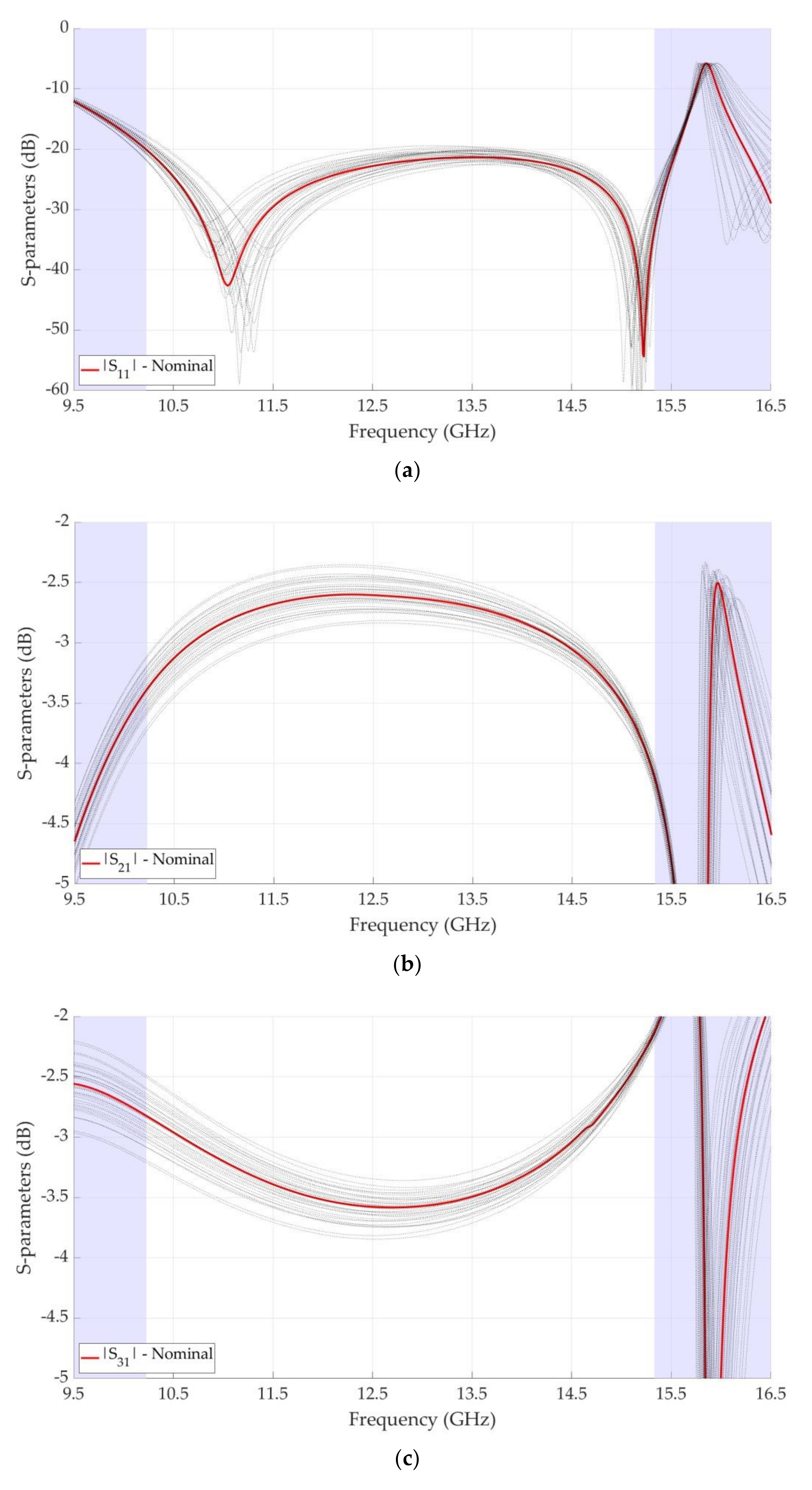
4. Tolerance Analysis

The proposed couplers are closed structures in hollow metallic waveguides with no dielectric; thus, a CNC milling machine manufacturing process is well suited for their fabrication. Most modern CNC standards have tolerances in the range of ±0.05 mm. In order to highlight the design robustness and reliability, a tolerance analysis on the most critical HC1 geometrical parameters was carried out. In particular, the slot length sl, the slot width sw, the slot separation sd, the slot distance from edge d and the gap g were swept in a range of ±0.10 mm from the nominal values of Table 1, for a total of 32 simulations. Tolerance analysis results are reported in Figure 5, and show little deviation from nominal values in the bandwidth even with an increased tolerance range with respect to state-of-the-art processes.

5. Conclusions

A novel geometry for single-ridge, air-filled waveguide quadrature hybrid couplers was presented, using a slotted ridge as a central coupling block. Two designs were outlined by acting on the number of slots and their dimensions, leading to an improved bandwidth and amplitude imbalance between the direct and coupled ports. The small size is a key feature that was obtained by means of a compact coupling section and single-layer implementation. Simulated results were reported both in frequency and time domains, showing a very good agreement with each other. A fractional bandwidth up to 46.88% and a maximum dimension of 1.18 wavelengths were obtained, leading to the best trade-off between performance and length among the state-of-the-art literature. In addition to this, in order to highlight the design robustness and reliability, a tolerance analysis of the most critical geometrical parameters with respect to modern CNC milling machine manufacturing standards was provided.

Author Contributions

Conceptualization, R.V.G.; data curation, G.S. and R.R.; formal analysis, G.S. and R.V.G.; investigation, G.S. and R.R.; methodology, R.V.G.; project administration, R.V.G.; resources, F.A. and R.V.G.; supervision, R.V.G.; validation, G.S. and R.R.; visualization, R.R. and R.V.G.; writing—original draft, G.S. and R.R.; writing—review and editing, G.S., R.R., F.A. and R.V.G. All authors have read and agreed to the published version of the manuscript.

Funding

This research received no external funding.

Data Availability Statement

Data are contained within the article.

Conflicts of Interest

The authors declare no conflict of interest.

References

  1. Pozar, D.M. Microwave Engineering, 4th ed.; John Wiley & Sons: Hoboken, NJ, USA, 2011. [Google Scholar]
  2. Nasr, A.M.H.; Safwat, A.M.E. Tightly coupled directional coupler using slotted-microstrip line. IEEE. Trans. Microw. Theory Tech. 2018, 66, 4462–4470. [Google Scholar] [CrossRef]
  3. Roshani, S.; Yahya, S.I.; Roshani, S.; Rostami, M. Design and fabrication of a compact branch-line coupler using resonators with wide harmonics suppression band. Electronics 2022, 11, 793. [Google Scholar] [CrossRef]
  4. Farahani, M.; Akbari, M.; Nedil, M.; Denidni, T.A.; Sebak, A.R. A novel low-loss millimeter-wave 3-db 90° ridge-gap coupler using large aperture progressive phase compensation. IEEE Access 2017, 5, 9610–9618. [Google Scholar] [CrossRef]
  5. Ali, M.M.M.; Shams, S.I.; Sebak, A.-R. Printed ridge gap waveguide 3-db coupler: Analysis and design procedure. IEEE Access 2018, 6, 8501–8509. [Google Scholar] [CrossRef]
  6. Dai, Y.-S.; Lu, Y.-L.; Luo, Q.-S.; Zhan, B.-Z.; Wang, X.; Jiang, Y.-B. A microminiature 3db multilayer double-octave hybrid coupler using ltcc. In Proceedings of the 2005 Asia-Pacific Microwave Conference, Suzhou, China, 4–7 December 2005; pp. 1–3. [Google Scholar] [CrossRef]
  7. Fahmi, M.M.; Ruiz-Cruz, J.A.; Zaki, K.A.; Piloto, A.J. Multilayer multi-section broadband ltcc stripline directional couplers. In Proceedings of the 2007 IEEE/MTT-S International Microwave Symposium, Honolulu, HI, USA, 3–8 June 2007; pp. 173–176. [Google Scholar] [CrossRef]
  8. Ruiz-Cruz, J.A.; Zhang, Y.; Zaki, K.A.; Piloto, A.J.; Rebollar, J.M. Ridge waveguide branch-line directional couplers for wideband applications and ltcc technology. In Proceedings of the IEEE MTT-S International Microwave Symposium Digest, Long Beach, CA, USA, 17 June 2005; pp. 1219–1222. [Google Scholar] [CrossRef]
  9. Wang, Y.; Fu, Y. A broadband waveguide power splitter and combiner using in spatial power combining amplifier. In Proceedings of the 2011 International Conference on Electronics, Communications and Control (ICECC), Ningbo, China, 9–11 September 2011; pp. 4074–4077. [Google Scholar] [CrossRef]
  10. Beyer, R.; Rosenberg, U. Compact top-wall hybrid/coupler design for extreme broad bandwidth applications. In Proceedings of the IEEE MTT-S International Microwave Symposium Digest, Long Beach, CA, USA, 17 June 2005; pp. 1227–1230. [Google Scholar] [CrossRef]
  11. Alfonso, E.; Zaman, A.U.; Pucci, E.; Kildal, P. Gap waveguide components for millimetre-wave systems: Couplers, filters, antennas, mmic packaging. In Proceedings of the 2012 International Symposium on Antennas and Propagation (ISAP), Nagoya, Japan, 29 October–2 November 2012; pp. 243–246. [Google Scholar]
  12. Zarifi, D.; Shater, A.R. Design of a 3-db directional coupler based on groove gap waveguide technology. Wiley Microw. Opt. Technol. Lett. 2017, 59, 1597–1600. [Google Scholar] [CrossRef]
  13. Gatti, R.V.; Rossi, R. A dual circularly polarized slot-fed horn array antenna with linear polarization-tracking feature. Wiley Int. J. RF Microw. Comput.-Aided Eng. 2018, 28, e21480. [Google Scholar] [CrossRef]
  14. Gatti, R.V.; Rossi, R. Wideband compact single-ridge waveguide to rectangular waveguide transitions with integrated e-plane bend. IET Electron. Lett. 2016, 52, 1699–1701. [Google Scholar] [CrossRef]
  15. Gatti, R.V.; Rossi, R.; Dionigi, M. X-band right-angle coaxial-to-single ridge waveguide compact transition with capacitive coupling. IET Electron. Lett. 2019, 55, 103–105. [Google Scholar] [CrossRef]
  16. Gatti, R.V.; Rossi, R. Single-ridge waveguide t-junctions for compact multilayer beam forming netwoks. Wiley Int. J. RF Microw. Comput.-Aided Eng. 2017, 27, e21056. [Google Scholar] [CrossRef] [Green Version]
  17. Shams, S.I.; Kishk, A.A. Design of 3-db hybrid coupler based on rgw technology. IEEE Trans. Microw. Theory Tech. 2017, 65, 3849–3855. [Google Scholar] [CrossRef]
  18. Soliman, M.Y.; Ali, M.M.M.; Shams, S.I.; Sree, M.F.A.; Fawzy, D.E.; Allam, A.M.M.A. Ridge gap waveguide wideband hybrid directional coupler for ka-band applications. In Proceedings of the 2020 7th International Conference on Electrical and Electronics Engineering (ICEEE), Antalya, Turkey, 14–16 April 2020; pp. 211–214. [Google Scholar] [CrossRef]
  19. Mahdavi, P.; Hosseini, S.E. Ku-band two-section branch-line coupler based on ridge gap waveguide technology. In Proceedings of the 2020 28th Iranian Conference on Electrical Engineering (ICEE), Tabriz, Iran, 4–6 August 2020; pp. 1–5. [Google Scholar] [CrossRef]
  20. Nasr, M.A.; Kishk, A.A. Analysis and design of broadband ridge-gap-waveguide tight and loose hybrid couplers. IEEE Trans. Microw. Theory Tech. 2020, 68, 3368–3378. [Google Scholar] [CrossRef]
  21. Fahmi, M.M.; Ruiz-Cruz, J.A.; Mansour, R.R. Contra-directional 3db 90° hybrid coupler in ridge waveguides using even and odd TE modes. In Proceedings of the 2019 IEEE MTT-S International Microwave Symposium (IMS), Boston, MA, USA, 2–7 June 2019; pp. 584–586. [Google Scholar] [CrossRef]
  22. Fahmi, M.M.; Ruiz-Cruz, J.A.; Mansour, R.R. Contra-directional ridge waveguide couplers: Design and applications. IEEE Trans. Microw. Theory Tech. 2019, 67, 4966–4975. [Google Scholar] [CrossRef]
  23. Fahmi, M.M.; Ruiz-Cruz, J.A.; Zaki, K.A. E and h-plane ridge waveguide couplers. Wiley Int. J. RF Microw. Comput.-Aided Eng. 2008, 18, 348–358. [Google Scholar] [CrossRef]
Figure 1. Hybrid coupler 1 (HC1) geometry. (a) Top view. (b) Three-dimensional view.
Electronics 11 01538 g001aElectronics 11 01538 g001b
Figure 2. Hybrid coupler 1 (HC1) simulated performance. (a) Frequency-domain scattering parameters. (b) Time-domain scattering parameters. (c) Amplitude imbalance. (d) Phase difference.
Electronics 11 01538 g002aElectronics 11 01538 g002b
Figure 3. Hybrid coupler 2 (HC2) geometry. (a) Top view. (b) Three-dimensional view.
Electronics 11 01538 g003aElectronics 11 01538 g003b
Figure 4. Hybrid coupler 2 (HC2) simulated performance. (a) Frequency-domain scattering parameters. (b) Time-domain scattering parameters. (c) Amplitude imbalance. (d) Phase difference.
Electronics 11 01538 g004aElectronics 11 01538 g004b
Figure 5. Hybrid coupler 1 (HC1) tolerance analysis simulations. (a) |S11|. (b) |S21|. (c) |S31|. (d) |S41|. (e) Amplitude imbalance. (f) Phase difference.
Electronics 11 01538 g005aElectronics 11 01538 g005b
Table 1. Hybrid coupler 1 (HC1) geometrical parameters.
ParameterDescriptionHC1 Value (mm)
aWaveguide width13.00
bWaveguide height5.50
dSlot distance from edge1.32
gGap1.81
rhRidge height4.00
rwRidge width4.00
sdSlot separation8.98
slSlot length8.81
swSlot width2.17
tWall thickness1.50
Table 2. Hybrid coupler 2 (HC2) geometrical parameters.
ParameterDescriptionHC2 Value (mm)ParameterDescriptionHC2 Value (mm)
aWaveguide width13.00rwRidge width4.00
bWaveguide height5.50sd1Slot separation 14.75
cxNotch length7.79sd2Slot separation 23.13
cwNotch width0.82sl1Slot length 111.02
dSlot distance from edge1.97sl2Slot length 213.49
gGap2.45sw1Slot width 11.66
hCentral block height2.95sw2Slot width 22.57
rhRidge height4.00tWall thickness1.50
Table 3. Comparison with referenced works.
ReferenceTechnologyBW (GHz)FBW (%)Normalized Length (λ0)Layers
[17]RGW14.00–16.50 (1)16.391.571
[18]RGW31.80–35.5011.001.601
[19]RGW13.00–17.00 (2)26.671.261
[20]RGW15.00–23.0042.112.002
[21]SRW1.55–2.60 (2)50.600.402
[22]SRW4.25–5.7530.000.482
[23]SRW4.00–7.7063.253.501
[23]SRW3.15–5.3551.761.004
HC1SRW10.23–15.3339.910.831
HC2SRW9.57–15.4346.881.181
HC2SRW10.04–15.32 (3)41.641.201
(1) 14-dB BW; (2) 15-dB BW; (3) 1 dB max. amp. imb.
Publisher’s Note: MDPI stays neutral with regard to jurisdictional claims in published maps and institutional affiliations.

