Article

Anti-Jerk Optimal Preview Control Strategy to Enhance Performance of Active and Semi-Active Suspension Systems

Department of Mechanical and Aerospace Engineering, Gyeongsang National University, ReCAPT, Jinju 52828, Gyeongnam, Korea
*
Author to whom correspondence should be addressed.
Electronics 2022, 11(10), 1657; https://doi.org/10.3390/electronics11101657
Submission received: 4 May 2022 / Revised: 18 May 2022 / Accepted: 20 May 2022 / Published: 23 May 2022
(This article belongs to the Collection Predictive and Learning Control in Engineering Applications)

Abstract

:
This study aims to demonstrate how to compute the damping coefficient of a continuously variable damper for semi-active preview control suspensions while considering the sprung-mass jerk and the controller’s performance advantage. Optimal control theory is used to derive and validate the proposed preview approach to future road disturbances. Despite reduced body acceleration, semi-active suspensions with preview control display an increase in body jerk, implying that ride comfort may not be improved in practice. The optimal preview jerk controller for a semi-active system, on the other hand, can improve ride comfort without degrading road holding by minimizing the performance index that comprises the RMS value of jerk in addition to the RMS values of other outputs. The anti-jerk preview control suspension simulations considering frequency characteristics reveal a difference between suspension systems that consider jerk and those that ignore jerk. The time-domain simulations suggest that the proposed preview control strategy effectively to reduce body jerk, which other controllers cannot.

1. Introduction

Suspension systems in cars have three purposes: they sustain the vehicle’s weight, provide ride comfort, and keep the driver safe. In addition to improving the basic functions of passive suspension systems, active suspension systems are critical for the compensation of variations in vehicle height caused by payload and aerodynamic forces, as well as controlling vehicle attitude motion caused by acceleration, braking, and cornering forces [1]. The passive suspension system’s spring stiffness and damping coefficients are designed to respond to a wide range of road surfaces, vehicle speeds, temperature conditions, and other factors. As a result, fixed suspension elements severely restrict passive suspension’s ability to deal with a rare, low-probability occurrence. An active suspension system can alter a vehicle’s dynamic properties in response to a range of disturbances that affect the vehicle’s dynamic motion [2]. In [3,4], the authors have designed a robust sliding mode-based active suspension control to improve the ride comfort and road-holding capability. A mixed-sensitivity control approach with the application of an active suspension system is used in [5] to improve the suspension performance. In [6], nonlinear actuator dynamics are considered for an active suspension system to minimize sprung-mass acceleration, suspension deflection, tire deflection to improve the ride comfort and road-holding capability. Although active suspension-based control strategies enhance the ride comfort and road-holding capability of the vehicle, the active suspension system requires too much energy to send to hydraulic actuators. In contrast to active suspensions, the semi-active pneumatic suspension system, which only requires a modest amount of energy to change damping coefficients or spring constants, is more practical [7,8]. Therefore, semi-active suspension-based control strategies are very useful to improve the ride comfort and road-holding capabilities, respectively; see the review article [9]. When ride comfort is prioritized, the performance of semi-active suspension with a variable damper can come close to that of active suspension [10,11,12,13]. Because the semi-active suspension system with a variable damper can only modify the dissipating energy rate without supplying energy, it has major limitations when height control and attitude motion control of a vehicle are required. A semi-active suspension system with variable stiffness, on the other hand, can solve the problem [14,15,16]. A multi-objective control scheme is proposed in [17], considering hydraulic adjustable dampers to realize the desired damping force to enhance vertical performance in practical applications. In [18], the performance of a recently developed magnetorheological damper on vibration control of a full-car semi-active suspension system is investigated. The use of road preview information increases the potential of active and semi-active suspension systems [19,20,21,22,23,24]. Direct detection from sensors installed in front of a vehicle or state assessment of a vehicle can be used to obtain a preview of road disruptions [25]. A preview control scheme is considered to be an impressive control strategy for vehicle performance against future information about disturbances. In this scheme, the future road irregularities are assumed to be measured in front of the vehicle and prepare the controller to use the oncoming input information. The control approach is based upon the optimal control law in which two controllers, i.e., feed-forward and feedback controllers, operate without creating any conflict. The preview control has vast applications in vehicle systems as well as other engineering fields; see a review by [22]. In [26,27], the authors used preview control for path tracking and future landing maneuvers. A preview control designed in [28,29] is used to improve the ride comfort and road holding of a vehicle during cornering. In [30] a fuzzy preview control strategy is developed to improve suspension performance of a half-car model. Based on the applications of a preview controller, the main objective of this paper is to investigate the role of an anti-jerk optimal preview controller in passenger ride comfort and vehicle handling.
Previous research has mostly focused on improving vehicle suspension performance by minimizing the cost function, which includes the RMS term for tire deflection, suspension deflection, and body acceleration. However, very little attention has been given to considering the vehicle body jerk and the commonly used body acceleration as passenger discomfort parameters. Therefore, body jerk needs to be minimized by including the RMS of a jerk in the corresponding performance index. The jerk, the time derivative of passenger acceleration, can have undesired effects on passenger comfort. Vehicle body jerk and acceleration are connected in a way that if acceleration is reduced it does not mean that the jerk is also reduced and vice versa, but if the body jerk and acceleration are reduced simultaneously then we can say that ride comfort is significantly improved. The body jerk is rarely discussed in automotive engineering. Therefore, very little research work has been carried out on reducing jerk. The RMS of a vehicle sprung-mass jerk was investigated and suggested by [31,32,33]. In their work, they used a very simple quarter-car model, where there is no damper and springs are installed between the sprung mass and unsprung mass. However, in our proposed model, we have considered these suspension components between the sprung mass and unsprung mass. In this work, the damping coefficient of a continuously variable damper of a semi-active suspension system is computed using a jerk controller. A semi-active suspension system is presented as an alternative to an active suspension system because it dissipates the required energy by adjusting the damping coefficient of a variable damper. The damper in a semi-active suspension system acts only when energy dissipation is required. Otherwise, it switches off. This switching behavior causes the vehicle body to jerk more often. Therefore, in this paper, performance indices such as RMS vehicle body jerk, RMS sprung-mass acceleration, RMS suspension deflection and RMS tire deflection are used to develop anti-jerk optimal preview controllers for semi-active suspension to improve ride comfort. The simulation results for harmonic inputs, random white noise, and bump velocity input show that the proposed control approach successfully reduces vehicle body jerk to improve ride comfort without degradation in road-holding capability.
The rest of this paper is organized as follows. Research motivation is presented in Section 2. Section 3 provides the problem formulation. Section 4 presents the formulation of the proposed control strategy. Simulation results and discussions are provided in Section 5. Finally, the concluding remarks are drawn in Section 6.

2. Research Motivation

In our earlier research, we looked at a semi-active pneumatic suspension with a constantly changing damper and an air spring that can change the suspension stiffness between three levels [15]. The sprung mass acceleration curve of a semi-active pneumatic suspension system using 0.1 s preview road information in Figure 1b has less amplitude than that of the semi-active pneumatic suspension system disregarding preview information in Figure 1a. However, the acceleration curve in Figure 1b showed more jerk than that in Figure 1a. The preview controller cannot be certain of improvement from the viewpoint of ride comfort. Therefore, a preview controller considering sprung-mass acceleration and jerk together need to be investigated.

3. Problem Formulation

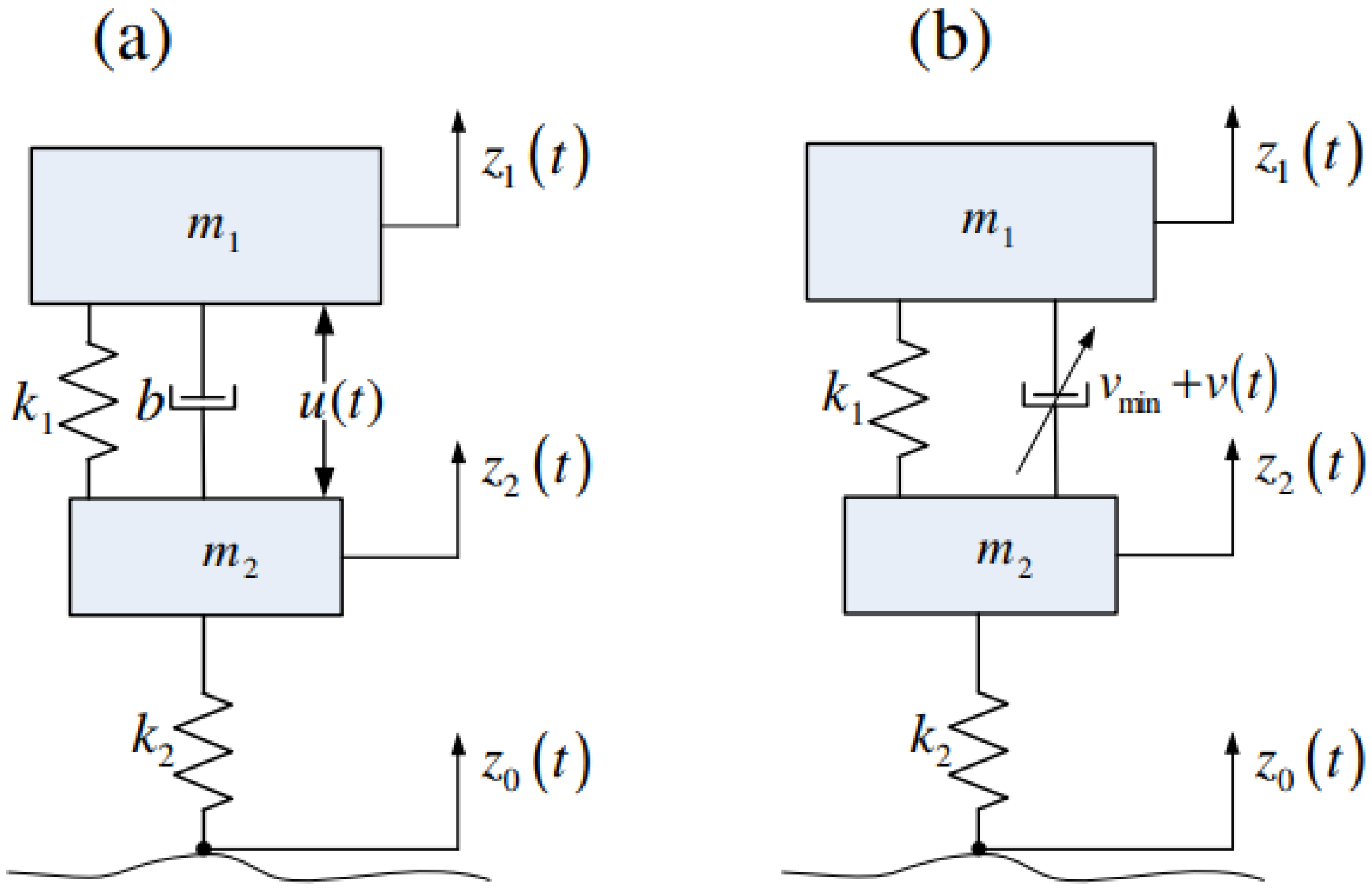
3.1. Quarter-Car Mathematical and Dynamic Models

In this section, a quarter-vehicle model with two degrees of freedom (DOF) is depicted in Figure 2. Figure 2a depicts a quarter car with an active suspension system, while Figure 2b depicts a quarter car with a semi-active suspension system. The dynamic equations of the proposed model are formulated in Equations (2) and (3), where m 1 , m 2 , b , v m i n + v ( t ) are known as sprung mass, unsprung mass, passive damping coefficient and variable damper coefficient, respectively. k 1 represents suspension stiffness, while k 2 represents tire stiffness. z 1 , z 2 and z 0 represents the sprung-mass displacement, unsprung-mass displacement and road disturbance, respectively. The variable damper coefficient varies between v m i n and v m i n + v m a x and v m i n 0 . Therefore, the variable v ( t ) satisfies
0 v ( t ) v m a x
It is assumed that v m i n = b in the semi-active suspension system.
The dynamic equations for the active suspension system shown in Figure 2a can be described as following dynamic models:
m 1 z ¨ 1 + k 1 ( z 1 z 2 ) + b ( z ˙ 1 z ˙ 2 ) u = 0
m 2 z ¨ 2 + k 1 ( z 2 z 1 ) + b ( z ˙ 2 z ˙ 1 ) + k 2 ( z 2 z 0 ) + u = 0
Adding Equations (2) and (3) we obtain the following equation as:
z ¨ 2 = m 1 m 2 z ¨ 1 k 2 m 2 ( z 2 z 0 )
After taking time derivative to Equation (2), substituting Equation (4) yields
z 1 = k 1 m 1 z ˙ 1 b k 2 m 1 m 2 ( z 2 z 0 ) + k 1 m 1 z 2 ˙ b ( 1 m 1 + 1 m 2 ) z ¨ 1 + u ˙ m 1

3.2. Formulation for Optimal Control Design

The performance index, comprised of the weighting constants multiplied by squared terms of suspension deflection, tire deflection, vehicle body acceleration, and the vehicle body jerk, respectively, is given in (6) as
J = lim t 1 2 T 0 T [ ρ 1 ( z 1 z 2 ) 2 + ρ 2 ( z 2 z 0 ) 2 + ρ 3 z ¨ 1 2 + ρ 4 z 1 2 ] d t
where T is the total simulation time, ρ 1 , ρ 2 , ρ 3 , and ρ 4 are the weighting constants determined by control designers considering design conditions, such as roughness of road surface, vehicle speed, weather, and the purpose of a vehicle. Since this study’s main concern considers optimal ride qualities of simple vehicle models, the weighting set is selected for ride-comfort preference. The state vector consists of the states in Equation (7) which can be figured out in Figure 2 and the disturbance input is defined as the road velocity:
x = [ z 1 z 2 , z ˙ 1 , z 2 z 0 , z ˙ 2 , z ¨ 1 ] , w = z ˙ 0
where z 1 z 2 represents suspension deflection, z ˙ 1 represents the sprung-mass velocity, z 2 z 0 represent tire deflection, z ˙ 2 represents unsprung-mass velocity and z ¨ 1 is called sprung-mass acceleration. A state–space model representation of Equations (4) and (5) can be represented as a first-order differential equation for each state, and the jerk controller and the road velocity are considered to be system inputs.
x ˙ = A x + B u ˙ + D w
Matrices A , B and D are given by
A = 0 1 0 1 0 0 0 0 0 1 0 0 0 1 0 0 0 k 2 m 2 0 m 1 m 2 0 k 1 m 1 b k 2 m 1 m 2 k 1 m 1 b m t
B = 0 0 0 0 1 m 1 , D = 0 0 1 0 0 T
where m t = 1 m 1 + 1 m 2 .
The performance index in Equation (6) can be written in the quadratic form (10) of state vectors and jerk control input using Equations (5) and (7). The synthesized optimal preview jerk controller minimizes a performance index that compromises measures of ride comfort, suspension deflection, road holding, and jerk control.
J = lim x 1 2 T 0 T [ x T Q x + 2 x T N u ˙ + R u ˙ 2 ] d t
where Q is symmetric matrix and positive semi-definite and R is greater than zero, given by
Q = ρ 1 0 0 0 0 0 k 1 2 m 1 2 b k 1 k 2 m 1 2 m 2 k 1 2 m 1 2 b k 1 m t m 0 b k 1 k 2 m 1 2 m 2 ρ 2 + b k 2 2 m 1 2 m 2 2 b k 1 k 2 m 1 2 m 2 b 2 k 2 m t m 1 m 2 0 k 1 2 m 1 2 b k 1 k 2 m 1 2 m 2 k 1 2 m 1 2 b k 1 m t m 1 0 b k 1 m t m b 2 k 2 m t m 1 m 2 b k 1 m t m 1 ρ 3 + b 2 m t
N = 0 k 1 2 m 1 2 b k 2 2 m 1 2 m 2 k 1 2 m 1 2 b m t m 1 , R = 1 m 1 2
The disturbance w ( t ) is assumed to be white noise with zero mean value, and ( w ( τ ) , τ [ t , t + t p ] ) , the preview time t p is deterministically known. As given in [15], the co-variance of w ( t ) is used to construct the road input for the simulation.
E [ w ( t 1 ) w ( t 2 ) ] = 2 π a V δ ( t 1 t 2 )
where a = 0.15 m represents the road’s roughness for the asphalt road. V represents the vehicle speed of 20 m/s. Referring to Equations (15) and (17), the jerk control input based on an active suspension system is similar to the control input given in [15] and can be expressed as given in (13).
u ˙ 0 ( t ) = f x ( τ ) , w ( σ ) , t o τ t , t o σ t + t p

4. Controller Design

4.1. Active Suspension System

To simplify the equations, the following notations are defined:
A n = A BR 1 N T , Q n = Q NR 1 N T
where Q n is assumed to be nonnegative definite. Furthermore, assuming that the pair ( A n , B ) is stable and that ( A n , Q n 1 / 2 ) is detectable as proved in [10], the jerk controller that minimizes the performance index given in (10) can be derived using optimal control theory.
u ˙ 0 ( t ) = R 1 [ ( N T + B T P ) x ( t ) + B T r ( t ) ]
where P can be obtained by solving the Algebraic Riccati Equation (16) and is a positive definite solution.
PA n + A n T P PBR 1 B T P + Q n = 0
and vector r ( t ) satisfies
r ( t ) = 0 t p e A c T σ PD w ( t + σ ) d σ
where A c = A BR 1 ( N T + B T P ) = A n BR 1 B T P and A c is the closed-loop system matrix and asymptotically stable. Therefore, Equation (17) will be a decreasing function with time. Hence the influence of future road disturbance by more than about 0.3 s will be irrelevant to the system performance [20].
The optimal preview jerk controller in (15) is made up of two parts: a feedback part, R 1 ( N T + B T P ) x ( t ) , which is the same as the optimal feedback controller for the active system without preview, and a feed-forward part, R 1 B T r ( t ) , which is derived using road preview information. After t + t p , the region treats the unused preview information regarding the road surface velocity as zero road slope. The optimal controller with no preview is identical to the optimal preview controller with zero preview length due to its linear feature. As a result, if the preview information is untrustworthy or does not work properly, the optimal preview jerk controller can still be used as a standard optimal feedback controller by omitting the feed-forward element. For preview information, if the future measured or detected road surface is closer to the real road surface than the zero slope, the optimal preview controller outperforms the optimal regular feedback controller despite minor measurement and estimation mistakes in preview information. Non-preview information causes r ( t ) = 0 , as shown in Equation (15), and the feed-forward element is thus ignored. Integrating the optimal preview jerk controller, u ˙ 0 in terms of time, yields the optimal control force u 0 , which must be determined for practical implementation.
u 0 = t [ c 1 ( z 1 z 2 ) + c 2 z ˙ 1 + c 3 ( z 2 z 0 ) + c 4 z ˙ 2 + c 5 z ¨ 1 + m 1 r 5 ] d t
where c i is control gain and r 5 is the fifth element of the vector r ( t ) .

4.2. Semi-Active Suspension System

The proposed model is envisioned as an active system with specific constraints and limitations. Under dynamic equality and inequality constraints, the variable damping coefficient boundary conditions allow the control input to minimize the corresponding objective function. As a result, the controller’s primary goal v ( t ) is to reduce the difference in control forces produced by active and semi-active systems. The variable damper’s desired control force can be represented as:
u ( t ) = v ( t ) ( z ˙ 1 z ˙ 2 )
The controller, v ( t ) , for the semi-active system minimizes ( u 0 u ) 2 . The strategy to determine v ( t ) is well known from the previous works [15]. For simplicity, g ( t ) is defined by g ( t ) = x 2 x 4 and v ( t ) is considered to be unchanged if g ( t ) = 0 . Otherwise, the well-established rule for determining the damping coefficient is
v ( t ) = u 0 g ( t ) < 0 , 0 u 0 g ( t ) > v m a x g ( t ) 2 , v m a x o t h e r w i s e , u 0 g ( t )
In the simulation, after replacing a constant damping coefficient, b, in matrix A with v m i n + v ( t ) , solving the time varying dynamic system, x ˙ = A ( t ) x + D w , yields x ( t ) .

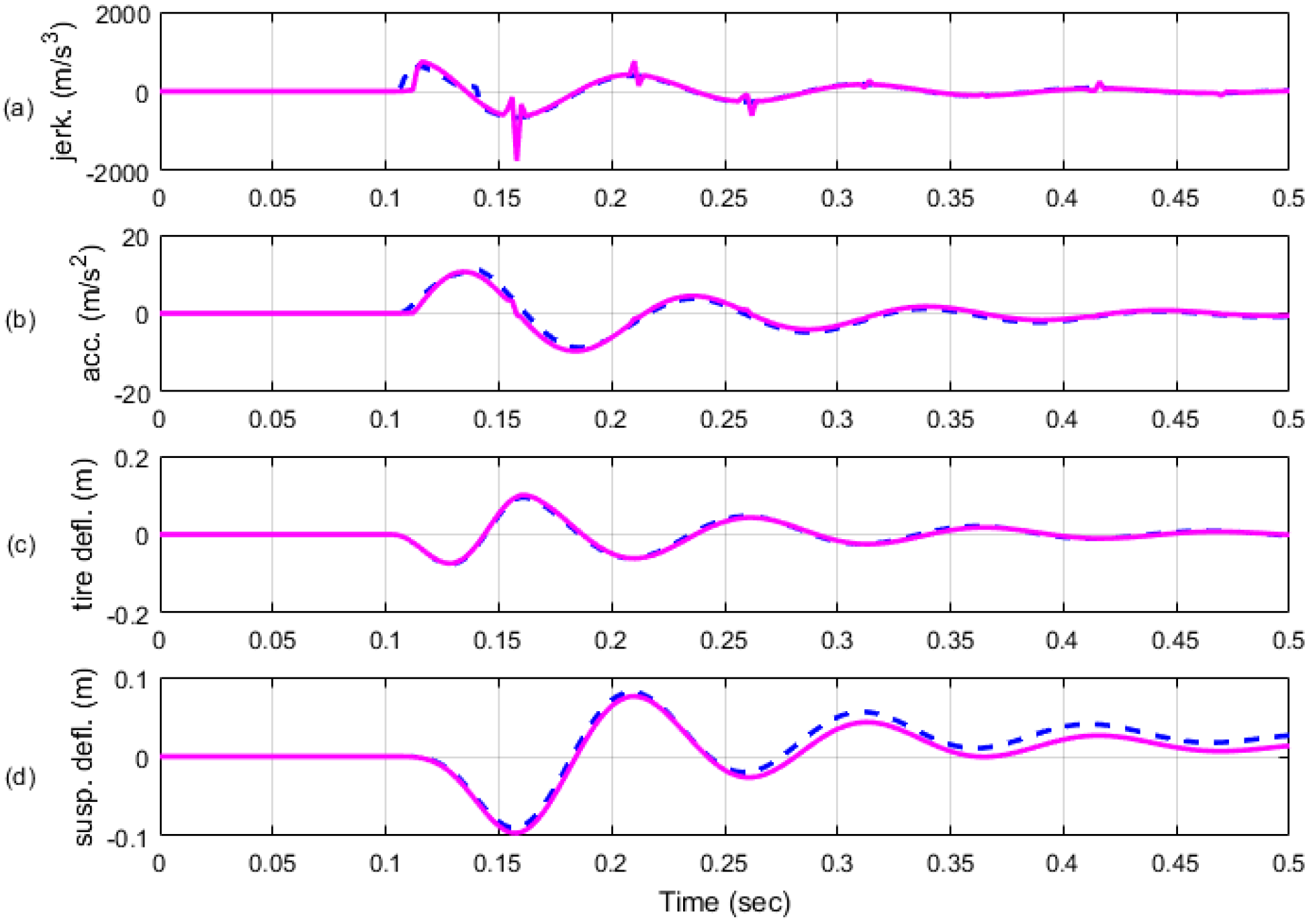
5. Analysis of Simulation Results

The performance of a 2-DOF quarter-car model with both active and semi-active suspension systems was simulated in Matlab. The simulation’s data are as follows:
m 2 m 1 = 0.1 , k 2 m 1 = 360 [ N m K g ] , k 1 m 1 = 30 [ N m K g ] , v m i n m 1 = 0.5 [ N s m K g ] , v m a x m 1 = 14 [ N s m K g ]
Two sets of weighting factors included in the performance indices are shown in Table 1. The first weighting set augmented to include vehicle jerk consists of ρ 1 = 4 × 10 4 , ρ 2 = 4 × 10 7 , ρ 3 = 10 2 and 1 for RMS jerk. The second set neglecting jerk is composed of ρ 1 = 10 3 , ρ 2 = 10 4 , ρ 3 = 1 and 0 for RMS jerk. These two weighting sets are selected because an active system with the first set considering the jerk term has almost the same performance as the active system with the second set ignoring the jerk term. As one proof, Figure 3a–c show that the frequency characteristics produced by optimal active controllers with two weighting sets are nearly identical to each other at disregarding preview. Another proof in Table 2 means that a quarter vehicle with an active system with the first weighting set achieves almost the same RMS suspension deflection, tire deflection, body acceleration and jerk, and total performance as the second set after those vehicle models have run on asphalt road. However, optimal preview controllers with two weighting sets improve system performance differently. Figure 3a–c show that active preview control considering the jerk term has globally better improvement in both ride comfort and road-holding capabilities than preview active control ignoring the jerk term. As a typical example, time responses of two semi-active systems with 0.1 s preview time to harmonic input in Figure 4 demonstrate the difference between two weighting sets. It is clear from Figure 4 that the performance of a semi-active system ignoring the jerk term with preview contains large jerk phenomena in time response to a 25 rad/s sinusoidal road input. However, as a performance comparison in the time domain, Figure 4 shows that a better system response in the viewpoint of both ride comfort and road holding is achieved by the first weighting set considering jerk term compared to those by the second set.
In Figure 5, the simulation results in asphalt road tests show graphically different performances of two semi-active systems with preview. Every performance component in Figure 5 is computed and is expressed in Table 3. The performances according to the two weighting sets in Table 3 numerically demonstrate that the proposed strategy can improve much more in both and ride-comfort viewpoints than the strategy neglecting jerk. Figure 5 shows that compared to the second weighting set, vehicle body jerks are 61.9% and body acceleration is 14.6%, respectively, improved for the first weighting set. Hence, a significant improvement in ride comfort is achieved at the cost of 5% degradation in road-holding capability. Figure 6a,b shows the bump position input and bump velocity input, respectively. The height of the bump is 10 cm. Figure 7 shows the simulation results for vehicle body jerk, body acceleration, tire deflection and suspension deflection, respectively. Figure 7a shows that the vehicle body jerk is significantly reduced for the first weighting set showing an improvement in ride comfort. On the other hand, the tire deflection, which is an important ride-comfort parameter, is similar for both weighting sets. Hence, it is proved that the proposed control approach for the bump input demonstrates that the vehicle with the semi-active suspension system with 0.1 s preview information enhances ride comfort by reducing the vehicle body jerk without any degradation in road-holding capability.
A question arises about the implementation of the proposed strategy, because, due to availability of the force actuator, it is desirable to use control force. Therefore, the proposed jerk controller can be integrated before applying to the actual system. However, a discrete time implementation of their derivative is also possible, as suggested by [33].

6. Conclusions

In this work, the damping coefficient of a continuously variable damper of a semi-active suspension system is computed. An anti-jerk optimal preview control law of an active and an anti-jerk optimal variable damping coefficient of a semi-active suspension systems is designed to reduce body jerk and other outputs to improve ride comfort. Two different weighting sets were proposed to check the effectiveness of including the weighting factor for body jerk for semi-active system. The control force obtained by integrating the jerk controller is needed to calculate the variable damper coefficient for practical application. The simulation results are carried out for frequency- and time-domain characteristics. The frequency-domain characteristics proved the effectiveness of the proposed optimal preview controller over the non-preview controller. The simulation results for the time-domain characteristics showed that the suggested anti-jerk optimal preview controller improved the performance of the semi-active suspension system by reducing body jerk, enhancing ride comfort without any degradation in road-holding capability.

Author Contributions

I.Y. surveyed the background of this research, presented the problem formulation and designed the control strategy along with MATLAB simulations for the addressed problem. E.A. helped in validation of the research work and in reviewing the manuscript, and assisted in technical writing and MATLAB simulations, I.Y. conceptualized the research idea and supervised the research. All authors have read and agreed to the published version of the manuscript.

Funding

This work was supported by the Gyeongsang National University Fund for Professors on Sabbatical Leave, 2020.

Acknowledgments

I want to appreciate Saeid Bashash who provided me with the opportunity to conduct research in the department of Mechanical Engineering, San Jose State University, CA 95192-008, California, USA.

Conflicts of Interest

The authors declare no conflict of interest.

References

  1. Ahmad, E.; Iqbal, J.; Arshad Khan, M.; Liang, W.; Youn, I. Predictive Control Using Active Aerodynamic Surfaces to Improve Ride Quality of a Vehicle. Electronics 2020, 9, 1463. [Google Scholar] [CrossRef]
  2. Van der Sande, T.; Gysen, B.; Besselink, I.; Paulides, J.; Lomonova, E.; Nijmeijer, H. Robust control of an electromagnetic active suspension system: Simulations and measurements. Mechatronics 2013, 23, 204–212. [Google Scholar] [CrossRef]
  3. Rath, J.J.; Defoort, M.; Sentouh, C.; Karimi, H.R.; Veluvolu, K.C. Output-Constrained Robust Sliding Mode Based Nonlinear Active Suspension Control. IEEE Trans. Ind. Electron. 2020, 67, 10652–10662. [Google Scholar] [CrossRef]
  4. Zhou, C.; Liu, X.; Chen, W.; Xu, F.; Cao, B. Optimal sliding mode control for an active suspension system based on a genetic algorithm. Algorithms 2018, 11, 205. [Google Scholar] [CrossRef] [Green Version]
  5. Formentin, S.; Karimi, A. A data-driven approach to mixed-sensitivity control with application to an active suspension system. IEEE Trans. Ind. Inform. 2012, 9, 2293–2300. [Google Scholar] [CrossRef] [Green Version]
  6. Kilicaslan, S. Control of active suspension system considering nonlinear actuator dynamics. Nonlinear Dyn. 2018, 91, 1383–1394. [Google Scholar] [CrossRef]
  7. Liu, C.; Chen, L.; Yang, X.; Zhang, X.; Yang, Y. General theory of skyhook control and its application to semi-active suspension control strategy design. IEEE Access 2019, 7, 101552–101560. [Google Scholar] [CrossRef]
  8. Desai, R.M.; Jamadar, M.E.H.; Kumar, H.; Joladarashi, S.; Rajasekaran, S.; Amarnath, G. Evaluation of a commercial MR damper for application in semi-active suspension. SN Appl. Sci. 2019, 1, 1–10. [Google Scholar] [CrossRef] [Green Version]
  9. Soliman, A.; Kaldas, M. Semi-active suspension systems from research to mass-market—A review. J. Low Freq. Noise Vib. Act. Control. 2021, 40, 1005–1023. [Google Scholar] [CrossRef] [Green Version]
  10. Hać, A. Optimal linear preview control of active vehicle suspension. Veh. Syst. Dyn. 1992, 21, 167–195. [Google Scholar] [CrossRef]
  11. Qin, Y.; Xiang, C.; Wang, Z.; Dong, M. Road excitation classification for semi-active suspension system based on system response. J. Vib. Control. 2018, 24, 2732–2748. [Google Scholar] [CrossRef]
  12. Qin, Y.; Langari, R.; Wang, Z.; Xiang, C.; Dong, M. Road excitation classification for semi-active suspension system with deep neural networks. J. Intell. Fuzzy Syst. 2017, 33, 1907–1918. [Google Scholar] [CrossRef]
  13. Paulides, J.J.; Encica, L.; Lomonova, E.A.; Vandenput, A.J. Design considerations for a semi-active electromagnetic suspension system. IEEE Trans. Magn. 2006, 42, 3446–3448. [Google Scholar] [CrossRef] [Green Version]
  14. Tanahashi, H.; Shindo, K.; Nogami, T.; Oonuma, T. Toyota Electronic Modulated Air Suspension for the 1986 Soarer; Technical Report; SAE Technical Paper; SAE International: Warrendale, PA, USA, 1987. [Google Scholar]
  15. Youn, I.; Hać, A. Semi-active suspensions with adaptive capability. J. Sound Vib. 1995, 180, 475–492. [Google Scholar] [CrossRef]
  16. Emura, J.; Kakizaki, S.; Yamaoka, F.; Nakamura, M. Development of the semi-active suspension system based on the sky-hook damper theory. SAE Trans. 1994, 103, 1110–1119. [Google Scholar]
  17. Ma, X.; Wong, P.K.; Zhao, J. Practical multi-objective control for automotive semi-active suspension system with nonlinear hydraulic adjustable damper. Mech. Syst. Signal Process. 2019, 117, 667–688. [Google Scholar] [CrossRef]
  18. Yoon, D.S.; Kim, G.W.; Choi, S.B. Response time of magnetorheological dampers to current inputs in a semi-active suspension system: Modeling, control and sensitivity analysis. Mech. Syst. Signal Process. 2021, 146, 106999. [Google Scholar] [CrossRef]
  19. Bender, E. Optimum Linear Preview Control with Application to Vehicle Suspension. ASME J. Basic Eng. 1968, 90, 213–221. [Google Scholar] [CrossRef]
  20. Hac, A.; Youn, I. Optimal Semi-Active Suspension with Preview Based on a Quarter Car Model. J. Vib. Acoust. 1992, 114, 84–92. [Google Scholar] [CrossRef]
  21. Thompson, A.; Pearce, C. RMS values for force, stroke and deflection in a quarter-car model active suspension with preview. Veh. Syst. Dyn. 2003, 39, 57–75. [Google Scholar] [CrossRef]
  22. Birla, N.; Swarup, A. Optimal preview control: A review. Optim. Control. Appl. Methods 2015, 36, 241–268. [Google Scholar] [CrossRef]
  23. Göhrle, C.; Schindler, A.; Wagner, A.; Sawodny, O. Model predictive control of semi-active and active suspension systems with available road preview. In Proceedings of the 2013 European Control Conference (ECC), Zurich, Switzerland, 17–19 July 2013; IEEE: Piscataway, NJ, USA, 2013; pp. 1499–1504. [Google Scholar]
  24. Jin, T.; Liu, Z.; Sun, S.; Ren, Z.; Deng, L.; Yang, B.; Christie, M.D.; Li, W. Development and evaluation of a versatile semi-active suspension system for high-speed railway vehicles. Mech. Syst. Signal Process. 2020, 135, 106338. [Google Scholar] [CrossRef]
  25. Thompson, A.; Pearce, C.E.M. Direct computation of the performance index for an optimally controlled active suspension with preview applied to a half-car model. Veh. Syst. Dyn. 2001, 35, 121–137. [Google Scholar] [CrossRef]
  26. Zhen, Z.; Jiang, S.; Jiang, J. Preview Control and Particle Filtering for Automatic Carrier Landing. IEEE Trans. Aerosp. Electron. Syst. 2018, 54, 2662–2674. [Google Scholar] [CrossRef]
  27. Zhen, Z.; Jiang, S.; Ma, K. Automatic carrier landing control for unmanned aerial vehicles based on preview control and particle filtering. Aerosp. Sci. Technol. 2018, 81, 99–107. [Google Scholar] [CrossRef]
  28. Zhou, H.; Gao, J.; Liu, H. Vehicle speed preview control with road curvature information for safety and comfort promotion. Proc. Inst. Mech. Eng. Part J. Automob. Eng. 2021, 235, 1527–1538. [Google Scholar] [CrossRef]
  29. Yim, S. Design of a preview controller for vehicle rollover prevention. IEEE Trans. Veh. Technol. 2011, 60, 4217–4226. [Google Scholar] [CrossRef]
  30. Choi, H.D.; Lee, C.J.; Lim, M.T. Fuzzy preview control for half-vehicle electro-hydraulic suspension system. Int. J. Control. Autom. Syst. 2018, 16, 2489–2500. [Google Scholar] [CrossRef]
  31. Hrovat, D.; Hubbard, M. Optimum Vehicle Suspensions Minimizing rms Rattlespace, Sprung-Mass Acceleration and Jerk. J. Dyn. Syst. Meas. Control. 1981, 103, 228–236. [Google Scholar] [CrossRef]
  32. Hrovat, D.; Hubbard, M. A comparison between jerk optimal and acceleration optimal vibration isolation. J. Sound Vib. 1987, 112, 201–210. [Google Scholar] [CrossRef]
  33. Rutledge, D.; Hubbard, M.; Hrovat, D. A two DOF model for jerk optimal vehicle suspensions. Veh. Syst. Dyn. 1996, 25, 113–136. [Google Scholar] [CrossRef]
Figure 1. Steady-state response of a semi-active pneumatic suspension system to a harmonic input of frequency 25 (rad/s), body acceleration 0.01   z ¨ 1 : - - - - - -, suspension deflection ( z 1 z 2 ) : – – – – –, tire deflection ( z 1 z 0 ) : – - – - – -, road input z 0 : ———; (a) without preview (b) with preview 0.1 s.
Electronics 11 01657 g001
Figure 2. Mathematical quarter-car models with (a) active suspension system and (b) semi-active suspension system.
Electronics 11 01657 g002
Figure 3. (ac) Frequency characteristics of for active system with preview (0.1 s) and without preview using (i) 1st weighting set without preview: – – – – –, (ii) 2nd weighting sets without preview: - - - - -, (iii) 1st weighting sets with preview: – - – - – - – -, (iv) 2nd weighting sets with preview: ———.
Electronics 11 01657 g003
Figure 4. (ad) Time responses of semi-active system with 0.1 s preview time to harmonic input of frequency 25 (rad/s) using (i) 1st weighting sets: – – – –; (ii) 2nd weighting sets: ——–.
Electronics 11 01657 g004
Figure 5. (ad) Time responses of the semi-active system with 0.1 s preview time on asphalt road input using (i) 1st weighting sets: – – – –; (ii) 2nd weighting sets: ——–.
Electronics 11 01657 g005
Figure 6. Road disturbance (a) Bump position input: ——–; (b) Bump velocity input: - - - - - -.
Electronics 11 01657 g006
Figure 7. (ad) Time responses of semi-active system with 0.1 second preview time to bump input using (i) 1st weighting sets: – – – –; (ii) 2nd weighting sets: ——–.
Electronics 11 01657 g007
Table 1. Two types weighting factors used in performance indices.
Weighting ConstantsTargets1st Set2nd Set
ρ 1 Suspension deflection 5 × 10 5 10 3
ρ 2 Tire deflection 4 × 10 7 10 4
ρ 3 Sprung-mass acceleration 10 2 1
ρ 4 Sprung-mass jerk10
Table 2. Components of performance indices obtained by active suspension system after running on asphalt road.
Active System E ( x 1 2 ) E ( x 3 2 ) E ( x 5 2 ) E ( x ˙ 5 2 ) J avg
w / 2 nd set 100.00 100.00 100.00 100.00 100.00
w / 1 st set 97.81 99.54 101.92 101.02 99.11
Table 3. Components of performance indices obtained by semi-active suspension system with 0.1 s preview after running on asphalt road.
Semi-Active System w/Preview E ( x 1 2 ) E ( x 3 2 ) E ( x 5 2 ) E ( x ˙ 5 2 ) J avg
w / 2 nd set 100.00 100.00 100.00 100.00 100.00
w / 1 st set 183.0435 105.9470 85.4387 38.1152 103.1361
Publisher’s Note: MDPI stays neutral with regard to jurisdictional claims in published maps and institutional affiliations.

